SICK MRS1000 User manual
OPERATING INSTRUCTIONS
MRS1000 PeopleCounter
PeopleCounter

Described product
MRS1000 PeopleCounter (type code: MRS1104A-xxxxxxS01)
Manufacturer
SICK AG
Erwin-Sick-Str. 1
79183 Waldkirch
Germany
Legal information
This work is protected by copyright. Any rights derived from the copyright shall be
reserved for SICK AG. Reproduction of this document or parts of this document is
only permissible within the limits of the legal determination of Copyright Law. Any modi‐
fication, abridgment or translation of this document is prohibited without the express
written permission of SICK AG.
The trademarks stated in this document are the property of their respective owner.
© SICK AG. All rights reserved.
Original document
This document is an original document of SICK AG.
2O P E R A T I N G I N S T R U C T I O N S | MRS1000 PeopleCounter 8025783/1GI8/2022-09-14 | SICK
Subject to change without notice

Contents
1 About this document........................................................................ 5
1.1 Information on the operating instructions.............................................. 5
1.2 Explanation of symbols............................................................................ 5
2 Safety information............................................................................ 6
2.1 Intended use............................................................................................. 6
2.2 Improper use............................................................................................. 6
2.3 Cybersecurity............................................................................................ 6
2.4 Limitation of liability................................................................................. 7
2.5 Modifications and conversions................................................................ 7
2.6 Requirements for skilled persons and operating personnel.................. 7
2.7 Operational safety and specific hazards................................................. 8
3 Product description........................................................................... 9
3.1 Scope of delivery....................................................................................... 9
3.2 Status indicators....................................................................................... 9
3.3 Type label.................................................................................................. 9
3.4 Principle of operation............................................................................... 10
3.4.1 Measurement principle........................................................... 10
3.4.2 Person counting application................................................... 11
4 Transport and storage....................................................................... 13
4.1 Transport................................................................................................... 13
4.2 Unpacking.................................................................................................. 13
4.3 Transport inspection................................................................................. 13
4.4 Storage...................................................................................................... 13
5 Mounting............................................................................................. 14
5.1 Mounting instructions............................................................................... 14
5.2 Mounting position..................................................................................... 14
5.3 Mounting the device................................................................................. 15
6 Electrical installation........................................................................ 16
6.1 Wiring instructions.................................................................................... 16
6.2 Prerequisites for safe operation of the device........................................ 17
6.3 Connection diagram................................................................................. 19
6.4 Connection options................................................................................... 21
6.5 Connecting the device electrically........................................................... 22
7 Operation............................................................................................ 23
7.1 Opening user interface............................................................................. 23
7.2 Overview.................................................................................................... 23
7.3 User levels................................................................................................. 23
7.4 General settings........................................................................................ 24
7.5 PeCo settings............................................................................................ 25
CONTENTS
8025783/1GI8/2022-09-14 | SICK O P E R A T I N G I N S T R U C T I O N S | MRS1000 PeopleCounter 3
Subject to change without notice

7.6 Region of interest settings....................................................................... 27
7.7 Counter...................................................................................................... 28
7.8 Room capacity.......................................................................................... 29
7.9 Statistics.................................................................................................... 29
7.10 About......................................................................................................... 30
7.11 Communication via REST API................................................................... 30
7.12 Service and diagnostics: Operation with SOPAS ET............................... 32
7.12.1 Communication in SOPAS ET via SOPAS commands............ 33
8 Maintenance...................................................................................... 35
8.1 Maintenance plan..................................................................................... 35
8.2 Cleaning..................................................................................................... 35
9 Troubleshooting................................................................................. 36
9.1 General faults, warnings, and errors....................................................... 36
9.2 Repairs...................................................................................................... 36
9.3 Returns...................................................................................................... 36
9.4 Disposal..................................................................................................... 37
10 Technical data.................................................................................... 38
10.1 Features.................................................................................................... 38
10.2 Mechanics/electronics............................................................................. 38
10.3 Dimensioned drawing............................................................................... 39
10.4 Performance............................................................................................. 40
10.5 Interfaces.................................................................................................. 40
10.6 Ambient data............................................................................................. 40
11 Accessories........................................................................................ 41
12 Annex.................................................................................................. 42
12.1 Declarations of conformity and certificates............................................ 42
12.2 Licenses.................................................................................................... 42
CONTENTS
4O P E R A T I N G I N S T R U C T I O N S | MRS1000 PeopleCounter 8025783/1GI8/2022-09-14 | SICK
Subject to change without notice

1 About this document
1.1 Information on the operating instructions
These operating instructions provide important information on how to use devices from
SICK AG.
Prerequisites for safe work are:
•Compliance with all safety notes and handling instructions supplied.
•Compliance with local work safety regulations and general safety regulations for
device applications
The operating instructions are intended to be used by qualified personnel and electrical
specialists.
NOTE
Read these operating instructions carefully to familiarize yourself with the device and its
functions before commencing any work.
The operating instructions are an integral part of the product. Store the instructions
in the immediate vicinity of the device so they remain accessible to staff at all times.
Should the device be passed on to a third party, these operating instructions should be
handed over with it.
These operating instructions do not provide information on the handling and safe
operation of the machine or system in which the device is integrated. Information on
this can be found in the operating instructions for the machine or system.
1.2 Explanation of symbols
Warnings and important information in this document are labeled with symbols. Sig‐
nal words introduce the instructions and indicate the extent of the hazard. To avoid
accidents, damage, and personal injury, always comply with the instructions and act
carefully.
DANGER
…indicates a situation of imminent danger, which will lead to a fatality or serious
injuries if not prevented.
WARNING
…indicates a potentially dangerous situation, which may lead to a fatality or serious
injuries if not prevented.
CAUTION
…indicates a potentially dangerous situation, which may lead to minor/slight injuries if
not prevented.
NOTICE
…indicates a potentially harmful situation, which may lead to material damage if not
prevented.
NOTE
…highlights useful tips and recommendations as well as information for efficient and
trouble-free operation.
ABOUT THIS DOCUMENT 1
8025783/1GI8/2022-09-14 | SICK O P E R A T I N G I N S T R U C T I O N S | MRS1000 PeopleCounter 5
Subject to change without notice

2 Safety information
2.1 Intended use
The MRS1000PeopleCounter is a combination of a 3D LiDAR sensor (MRS1000)
and a SensorApp (PeopleCounter) developed for a people counting (PeopleCounting)
application.
Measurement data is generated in the form of a point cloud and people can be
identified by their contours. This process runs anonymously and without recording any
personal information.
Thanks to the four scan planes of the LiDAR sensor, the direction of movement of each
person is clearly established. On this basis, the person entry and exit area can be
determined and the maximum permissible number of people in a delineated area can
be monitored.
In order to always be able to keep an eye on the current utilization of the area, the
counting status is provided via the digital outputs of the device.
Thanks to the ability to combine or connect several devices in an existing network
(host/guest operation), it is also possible to monitor large areas with multiple access
points, such as shopping centers, airports or trade fair buildings.
SICK AG assumes no liability for losses or damage arising from the use of the product,
either directly or indirectly. This applies in particular to use of the product that does not
conform to its intended purpose and is not described in this documentation.
2.2 Improper use
Any use outside of the stated areas, in particular use outside of the technical specifica‐
tions and the requirements for intended use, will be deemed to be incorrect use.
•The device does not constitute a safety component in accordance with the respec‐
tive applicable safety standards for machines.
•The device must not be used in explosion-hazardous areas, in corrosive environ‐
ments or under extreme environmental conditions.
•Any use of accessories not specifically approved by SICK AG is at your own risk.
WARNING
Danger due to improper use!
Any improper use can result in dangerous situations.
Therefore, observe the following information:
■Product should be used only in accordance with its intended use.
■All information in the documentation must be strictly observed.
■Shut down the product immediately in case of damage.
2.3 Cybersecurity
Overview
To protect against cybersecurity threats, it is necessary to continuously monitor and
maintain a comprehensive cybersecurity concept. A suitable concept consists of organi‐
zational, technical, procedural, electronic, and physical levels of defense and considers
suitable measures for different types of risks. The measures implemented in this
product can only support protection against cybersecurity threats if the product is used
as part of such a concept.
2 SAFETY INFORMATION
6O P E R A T I N G I N S T R U C T I O N S | MRS1000 PeopleCounter 8025783/1GI8/2022-09-14 | SICK
Subject to change without notice

You will find further information at www.sick.com/psirt, e.g.:
•General information on cybersecurity
•Contact option for reporting vulnerabilities
•Information on known vulnerabilities (security advisories)
2.4 Limitation of liability
Relevant standards and regulations, the latest technological developments, and our
many years of knowledge and experience have all been taken into account when
compiling the data and information contained in these operating instructions. The
manufacturer accepts no liability for damage caused by:
■Non-adherence to the product documentation (e.g., operating instructions)
■Incorrect use
■Use of untrained staff
■Unauthorized conversions or repair
■Technical modifications
■Use of unauthorized spare parts, consumables, and accessories
2.5 Modifications and conversions
NOTICE
Modifications and conversions to the device may result in unforeseeable dangers.
Interrupting or modifying the device or SICK software will invalidate any warranty claims
against SICK AG. This applies in particular to opening the housing, even as part of
mounting and electrical installation.
2.6 Requirements for skilled persons and operating personnel
WARNING
Risk of injury due to insufficient training.
Improper handling of the device may result in considerable personal injury and material
damage.
■All work must only ever be carried out by the stipulated persons.
The following qualifications are required for various activities:
Table 1: Activities and technical requirements
Activities Qualification
Mounting, maintenance ■Basic practical technical training
■Knowledge of the current safety regulations in the workplace
Electrical installation,
device replacement
■Practical electrical training
■Knowledge of current electrical safety regulations
■Knowledge of the operation and control of the devices in their
particular application
Commissioning, configura‐
tion
■Basic knowledge of the computer operating system used
■Basic knowledge of the design and setup of the described
connections and interfaces
■Basic knowledge of data transmission
Operation of the device for
the particular application
■Knowledge of the operation and control of the devices in their
particular application
■Knowledge of the software and hardware environment for the
particular application
SAFETY INFORMATION 2
8025783/1GI8/2022-09-14 | SICK O P E R A T I N G I N S T R U C T I O N S | MRS1000 PeopleCounter 7
Subject to change without notice

2.7 Operational safety and specific hazards
Please observe the safety notes and the warnings listed here and in other sections
of this product documentation to reduce the possibility of risks to health and avoid
dangerous situations.
CAUTION
Optical radiation: Class 1 Laser Product
The accessible radiation does not pose a danger when viewed directly for up to 100
seconds. It may pose a danger to the eyes and skin in the event of incorrect use.
■Do not open the housing. Opening the housing may increase the level of risk.
■Current national regulations regarding laser protection must be observed.
Caution – Use of controls or adjustments or performance of procedures other than
those specified herein may result in hazardous radiation exposure.
It is not possible to entirely rule out temporary disorienting optical effects, particularly
in conditions of dim lighting. Disorienting optical effects may come in the form of
dazzle, flash blindness, afterimages, photosensitive epilepsy, or impairment of color
vision, for example.
WARNING
Electrical voltage!
Electrical voltage can cause severe injury or death.
■Work on electrical systems must only be performed by qualified electricians.
■The power supply must be disconnected when attaching and detaching electrical
connections.
■The product must only be connected to a voltage supply as set out in the require‐
ments in the operating instructions.
■National and regional regulations must be complied with.
■Safety requirements relating to work on electrical systems must be complied with.
WARNING
Risk of injury and damage caused by potential equalization currents!
Improper grounding can lead to dangerous equipotential bonding currents, which may
in turn lead to dangerous voltages on metallic surfaces, such as the housing. Electrical
voltage can cause severe injury or death.
■Work on electrical systems must only be performed by qualified electricians.
■Follow the notes in the operating instructions.
■Install the grounding for the product and the system in accordance with national
and regional regulations.
2 SAFETY INFORMATION
8O P E R A T I N G I N S T R U C T I O N S | MRS1000 PeopleCounter 8025783/1GI8/2022-09-14 | SICK
Subject to change without notice

3 Product description
3.1 Scope of delivery
The delivery of the device includes the following components:
Table 2: Scope of delivery
Item Component Comments
1 Device in the version ordered Depending on version
Without connecting cables and brackets
1 Set of protective caps for electri‐
cal connections
Attached to the connections
1 Printed safety notes, multilin‐
gual
Quick guide and general safety notes
The actual scope of delivery may differ for special designs, additional orders or due to
the latest technical changes.
3.2 Status indicators
2
1
Figure 1: Status indicators
1LED1
2LED2
LED1 (color) LED2 (color) Description
O (Red) O (Red) Start up, firmware update
Ö (Red)- Ö (Yellow)- Ö (Green)
Alternating for 20s
Identifying the device
Off Off Normal operation
O = illuminated; Ö = flashing
3.3 Type label
The type label gives information for identification of the device.
PRODUCT DESCRIPTION 3
8025783/1GI8/2022-09-14 | SICK O P E R A T I N G I N S T R U C T I O N S | MRS1000 PeopleCounter 9
Subject to change without notice

ETH I/O PWR
MRS1104A-111011S01
www.sick.com/1112242
Ident No.:
1112242
Serial No.:
13098912
DC 10-30V
Ptyp 13W max. 30W
Temp.: -30°C … +50°C IP65/67
MAC: 00:06:77:06:05:5E
Manufactured:
May 2019
MADE IN GERMANY
DO NOT REMOVE
SICK AG
D-79276 Reute
25
á
ß
9
12
65 4
3
87
Figure 2: MRS1000/LMS4500 PeopleCounter type label (example)
1Voltage supply, typical power, max. power, operating temperature, enclosure rating
2MAC address
3Conformity mark/certification mark, symbol: Observe the operating instructions!
4Manufacturer
5Production location, note: Do not remove type label
6Production date
7Part number
8Serial number
9Data Matrix code with product data and link to product page
ßWeb address of product page
àType code
áLabeling of connections: Ethernet (ETH), inputs/outputs (I/O), supply voltage (PWR)
3.4 Principle of operation
3.4.1 Measurement principle
The device is an opto-electronic LiDAR sensor that scans the outline of its surround‐
ings with the help of laser beams without making contact. The device measures its
surroundings in two-dimensional polar coordinates, relative to its measurement origin.
This is marked by a circular indentation in the center of the optics cover. If a laser beam
strikes an object, the position of that object is determined in terms of distance and
angle.
This is carried out in 4 spread-out scan layers (scan layers 1 to 4)
Figure 3: Scan layers
3 PRODUCT DESCRIPTION
10 O P E R A T I N G I N S T R U C T I O N S | MRS1000 PeopleCounter 8025783/1GI8/2022-09-14 | SICK
Subject to change without notice

3.4.2 Person counting application
The SensorApp developed for the people counting application uses the 4 scan planes
of the device to detect the direction of movement of people. One device is therefore
enough to identify where people enter and exit.
The special algorithm detects the outline of people, whereby even people walking next
to them are reliably identified.
The recorded data can be output via the digital outputs or the software interface.
If several access points are to be monitored, devices can be linked via the Sensor Fusion
function or the linking of inputs and outputs.
Sensor fusion (host/guest operation)
The Sensor Fusion function can be used to monitor areas with several access points.
To do so, the devices communicate via Ethernet connection by means of UDP (User
Datagram Protocol, Port: 2115). One device assumes the role of host and collects the
counting results of all linked devices (guest) in an overall result. The reactions set on
the host when the warning threshold or maximum permissible number of people is
reached (e.g. switching the outputs to control warning lights, digital outputs 1 to 3) are
adopted by all connected guests. The digital inputs for correcting the number of people
(digital inputs 6 and 7) are deactivated on the guests. A reset via digital input 8 at the
guest resets all devices, a reset at a guest only resets the respective device.
Power
I/O
Ethernet
Host
Guest
SOPASair
Figure 4: Host/guest operation
I/O link
Areas with multiple access points can be monitored by linking several devices via the
digital inputs and outputs. For this purpose, the counting pulses of one device (host,
data supplier) are forwarded via the digital output to the digital input of another device
(guest, data collector). By linking the output of a host with the input of a guest, the
collected results can be fed back. Transmission to a third device is also possible.
PRODUCT DESCRIPTION 3
8025783/1GI8/2022-09-14 | SICK O P E R A T I N G I N S T R U C T I O N S | MRS1000 PeopleCounter 11
Subject to change without notice

The I/O link is made as follows:
•Wiring of digital output 4 (host, data supplier) to digital input 7 (guest, data
collector) and digital output 5 (guest, data supplier) to digital input 6 (guest, data
collector)
•The set signal pulse length at the host (recommendation: 10ms) must be at least
twice as large as the set debounce time of the guest (recommendation: 5ms).
1
IN6OUT5OUT4
Device 2
(Guest)
IN7
IN6OUT5OUT4
Device 1
(Host)
IN7
2
IN6OUT5OUT4
Device 2
(Host + Guest)
IN7
IN6OUT5OUT4
Device 1
(Host + Guest)
IN7
3
IN6OUT5OUT4
Device 2
(Host + Guest)
IN7
IN6OUT5OUT4
Device 1
(Host)
IN7 IN6OUT5OUT4
Device 3
(Host + Guest)
IN7 IN6
OUT5
OUT4
Device X
(Guest)
IN7
Figure 5: Variants of the IO link
12devices, of which 1device is the host, 1device the guest. The data of both devices
is available in device 1. The current occupancy can be read out via SOPASair or via the
digital outputs only on device 1.
22devices, both devices are host and guest. The data of both devices is available in device
1and device 2. Please note that, with this link, the Counting correction function must be
deactivated on both devices. The current occupancy can be read out via SOPASair or via
the digital outputs on device 1and device 2.
33 or more devices, of which 1 device is the host, 1 or more devices are the host and
guest, 1 device is the guest. The data of all devices is available in device 1. Please note
that, with this link, the Counting correction function must be activated for device 2. The
current occupancy can be read out via SOPASair or via the digital outputs only on device
1.
When using digital outputs 1 to 3 (e.g. switching the outputs to control warning lights),
it must be noted that only those results are output which are available in the respective
device. Recommendation: Use only the digital outputs of the device on which the data
of all devices is available.
If the Counting correction function is deactivated for a host, only the counts of actually
recorded people are transmitted; manual corrections of the number of people in the
room made via SOPASair or the digital inputs of the data supplier are not.
3 PRODUCT DESCRIPTION
12 O P E R A T I N G I N S T R U C T I O N S | MRS1000 PeopleCounter 8025783/1GI8/2022-09-14 | SICK
Subject to change without notice

4 Transport and storage
4.1 Transport
NOTICE
Damage due to improper transport!
■The product must be packaged with protection against shock and damp.
■Recommendation: Use the original packaging.
■Note the symbols on the packaging.
■Do not remove packaging until immediately before you start mounting.
4.2 Unpacking
•To protect the device against condensation, allow it to equilibrate with the ambient
temperature before unpacking if necessary.
•Handle the device with care and protect it from mechanical damage.
•To avoid ingress of dust and water, only remove the protective elements, e.g.
protective caps of the electrical connections just before attaching the connecting
cable.
4.3 Transport inspection
Immediately upon receipt in Goods-in, check the delivery for completeness and for any
damage that may have occurred in transit. In the case of transit damage that is visible
externally, proceed as follows:
•Do not accept the delivery or only do so conditionally.
•Note the scope of damage on the transport documents or on the transport compa‐
ny's delivery note.
•File a complaint.
NOTE
Complaints regarding defects should be filed as soon as these are detected. Damage
claims are only valid before the applicable complaint deadlines.
4.4 Storage
•Electrical connections are provided with a protective cap.
•Do not store outdoors.
•Store in a place protected from moisture and dust.
•Recommendation: Use the original packaging.
•To allow any residual dampness to evaporate, do not package in airtight contain‐
ers.
•Do not expose to any aggressive substances.
•Protect from sunlight.
•Avoid mechanical shocks.
•Storage temperature: see "Technical data", page 38.
•Relative humidity: see "Technical data", page 38.
•For storage periods of longer than 3months, check the general condition of all
components and packaging on a regular basis.
TRANSPORT AND STORAGE 4
8025783/1GI8/2022-09-14 | SICK O P E R A T I N G I N S T R U C T I O N S | MRS1000 PeopleCounter 13
Subject to change without notice
5 Mounting
5.1 Mounting instructions
•Observe the technical data.
•Protect the sensor from direct sunlight.
•To prevent condensation, avoid exposing the device to rapid changes in tempera‐
ture.
•The mounting site has to be designed for the weight of the device.
•Protect the device from moisture, contamination, and damage.
•Make sure that the status indicator is clearly visible.
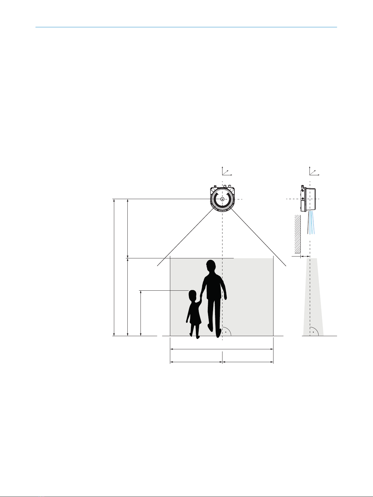
5.2 Mounting position
For reliable function, observe the following framework conditions when positioning the
device.
typ. 2,50 ... 3.50 1
max 2.10 3
min 0.80 4
typ. 3.50 6
8
5
+5°
+2.5°
–2.5°
0°
ß
x
y
zx
z
y
7 7
9
min 0.30 2
Figure 6: Mounting position
1Mounting height: Typically 2.50 to 3.50m; minimum 2.00m; max. 5.00m
2Minimum distance from origin of measurement to people
3Person size: Max. 2.10m
4Person size: Min. 0.80m
5Tilt of device around z-axis: Typically 0°; max. ±90°
6Horizontal detection area: Typically 3.50m; max. 10.00m
7Position of the device over the detection area: Typically central to prevent shading by
people walking by
8Detection area: Typically 3.50m x 2.10m (W x H); max. 10.00m x 2.10m (W x H)
5 MOUNTING
14 O P E R A T I N G I N S T R U C T I O N S | MRS1000 PeopleCounter 8025783/1GI8/2022-09-14 | SICK
Subject to change without notice

9Distance of the device to objects (e.g. walls): Observe scan plane angle (-2.5°/0°/+2.5°/
+5°), if needed increase distance or tilt device around y-axis
ßTilt of device around y-axis: Typically 0°; max. ±10°
Increase in counting accuracy
Also note the following information when selecting and setting up the detection area.
The following situations cause inaccuracies in counting and should therefore be
avoided:
•People who are stay in the detection area, special groups of people
•People who walk and stand very close to and behind one another in a crowd
•People who move into the detection area from the side.
•Doors which move into the detection area when opening and closing
•Objects located in the detection area.
•Height differences of the floor in the detection area (e.g. steps)
5.3 Mounting the device
1. Mount the device in a suitably prepared bracket using the fixing holes provided
(see figure 15, page 39). Mounting brackets are available as accessories, "Acces‐
sories", page 41.
2. Make the electrical connection. Attach and tighten a voltage-free cable, see "Con‐
necting the device electrically", page 22.
3. Switch on the supply voltage.
MOUNTING 5
8025783/1GI8/2022-09-14 | SICK O P E R A T I N G I N S T R U C T I O N S | MRS1000 PeopleCounter 15
Subject to change without notice

6 Electrical installation
6.1 Wiring instructions
NOTE
Pre-assembled cables can be found online at:
•www.sick.com/people-counter
NOTICE
Faults during operation and defects in the device or the system
Incorrect wiring may result in operational faults and defects.
■Follow the wiring notes precisely.
All electrical connections of the device are configured as M12 round connectors.
The enclosure rating stated in the technical data is achieved only with screwed plug
connectors or protective caps.
All circuits connected to the device must be configured as SELV or PELV circuits. SELV =
safety extra-low voltage, PELV = protective extra-low voltage.
Observe the following notes to ensure safe and trouble-free operation:
•Connect the connecting cables in a de-energized state. Do not switch on the
supply voltage until installation is complete and all connecting cables have been
connected to the device and control.
•Wire cross-sections in the supply cable from the customer’s power system should
be designed in accordance with the applicable standards. Protect the device with
an external slow-blow fuse of 5A at the beginning of the supply cable, viewed from
the voltage supply.
•The specified enclosure rating of the device when mounted is reached only if
suitable mating connectors or protective caps are used.
•Do not open the screwed housing of the device, since the warranty will then
become void.
•Turn the rotatable electrical connections max 270° from end position to end
position.
•Prior to connecting the I/O line, check the device configuration for the inputs/
outputs.
•Avoid tensile loads to the connecting cables.
•Maximum cable lengths for the voltage supply depending on the power supply
voltage used (conditions: cable cross-section 0.34mm², 20°C cable tempera‐
ture, 10V applied to the device, max. power consumption as per type label):
6.5m at 12V; 46.5m at 24V; 66.5m at 30V.
6 ELECTRICAL INSTALLATION
16 O P E R A T I N G I N S T R U C T I O N S | MRS1000 PeopleCounter 8025783/1GI8/2022-09-14 | SICK
Subject to change without notice
6.2 Prerequisites for safe operation of the device
WARNING
Risk of injury and damage caused by electrical current!
As a result of equipotential bonding currents between the device and other grounded
devices in the system, faulty grounding of the device can give rise to the following
dangers and faults:
•Dangerous voltages are applied to the metal housings.
•Devices will behave incorrectly or be destroyed.
•Cable shielding will be damaged by overheating and cause cable fires.
Remedial measures
•Only skilled electricians should be permitted to carry out work on the electrical
system.
•If the cable insulation is damaged, disconnect the voltage supply immediately and
have the damage repaired.
•Ensure that the ground potential is the same at all grounding points.
•Where local conditions do not meet the requirements for a safe earthing method,
take appropriate measures. For example, ensure low-impedance and current-carry‐
ing equipotential bonding.
The device is connected to the peripheral devices (any local trigger sensor(s), system
controller) via shielded cables. The cable shield – for the data cable, for example –
rests against the metal housing of the device.
The device can be grounded through the cable shield or through a blind tapped hole in
the housing, for example.
If the peripheral devices have metal housings and the cable shields are also in contact
with their housings, it is assumed that all devices involved in the installation have the
same ground potential.
This is achieved by complying with the following conditions:
■Mounting the devices on conductive metal surfaces
■Correctly grounding the devices and metal surfaces in the system
■If necessary: low-impedance and current-carrying equipotential bonding between
areas with different ground potentials
SICK
Device
7 46
Power Supply
U
= 8
= 9
1 2 3
I
5
System
Controller
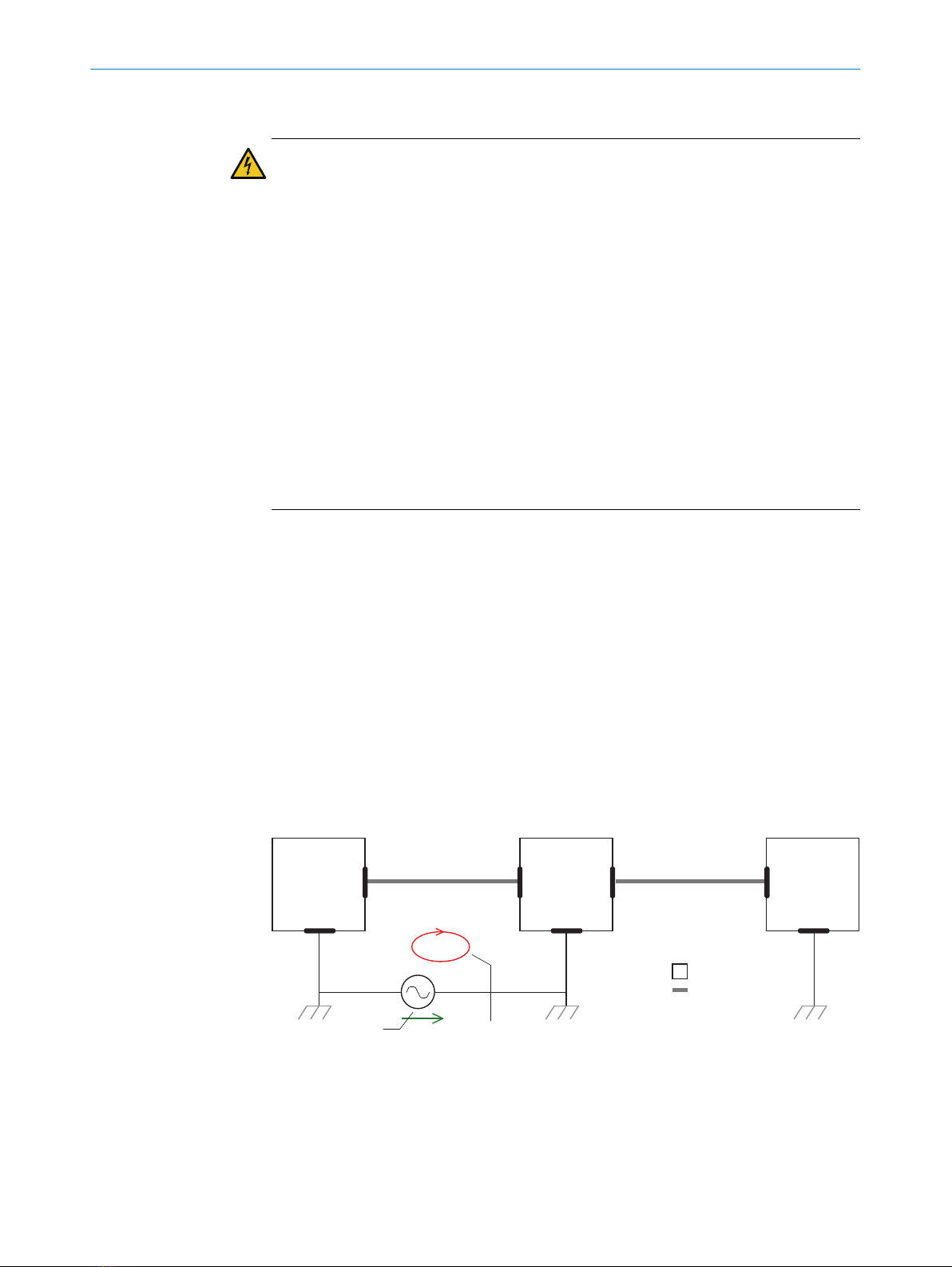
Figure 7: Example: Occurrence of equipotential bonding currents in the system configuration
1System controller
2Device
3Voltage supply
4Grounding point 2
5Closed current loop with equalizing currents via cable shield
ELECTRICAL INSTALLATION 6
8025783/1GI8/2022-09-14 | SICK O P E R A T I N G I N S T R U C T I O N S | MRS1000 PeopleCounter 17
Subject to change without notice
6Ground potential difference
7Grounding point 1
8Metal housing
9Shielded electrical cable
If these conditions are not fulfilled, equipotential bonding currents can flow along the
cable shielding between the devices due to differing ground potentials and cause the
hazards specified. This is, for example, possible in cases where there are devices within
a widely distributed system covering several buildings.
Remedial measures
The most common solution to prevent equipotential bonding currents on cable shields
is to ensure low-impedance and current-carrying equipotential bonding. If this equipo‐
tential bonding is not possible, the following solution approaches serve as a suggestion.
NOTICE
We expressly advise against opening up the cable shields. This would mean that the
EMC limit values can no longer be complied with and that the safe operation of the
device data interfaces can no longer be guaranteed.
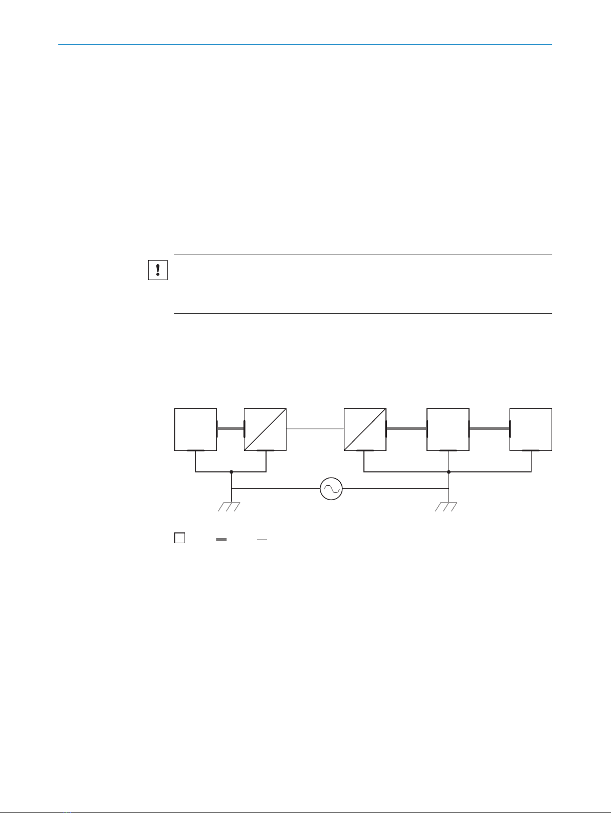
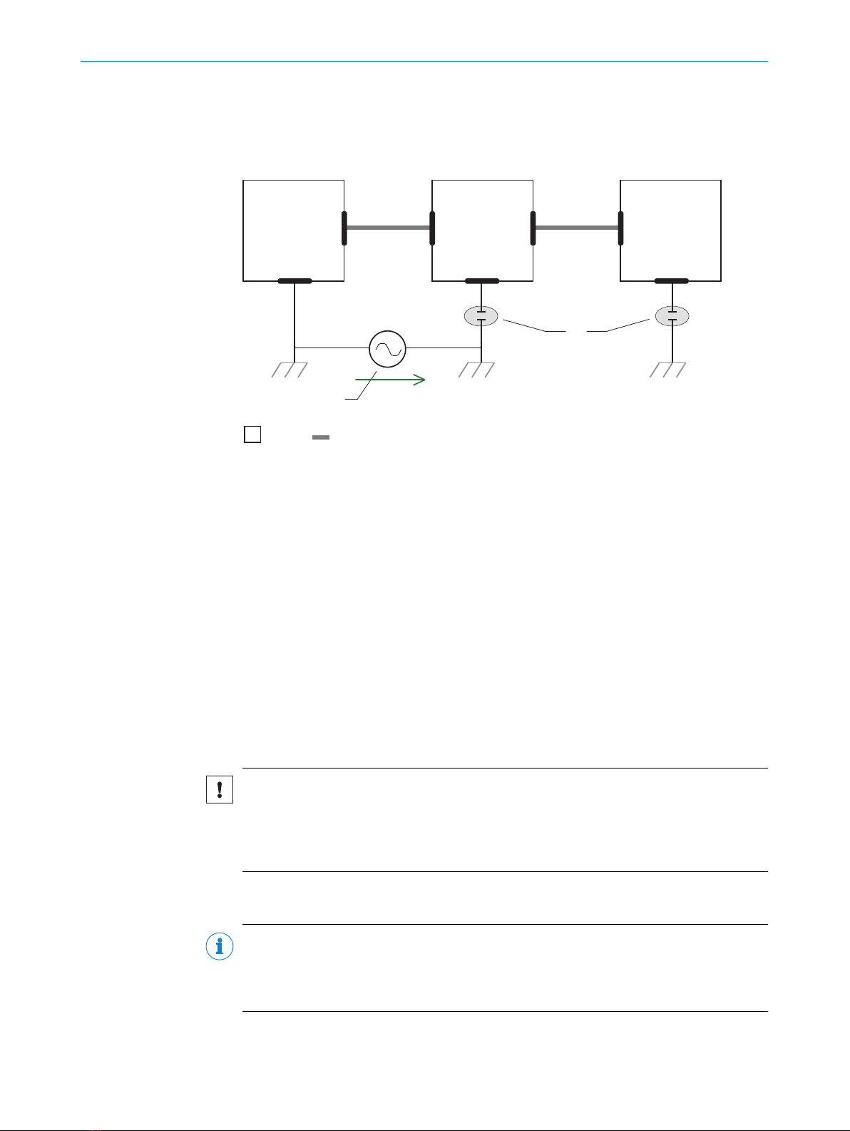
Measures for widely distributed system installations
On widely distributed system installations with correspondingly large potential differen‐
ces, the setting up of local islands and connecting them using commercially available
electro-optical signal isolators is recommended. This measure achieves a high degree
of resistance to electromagnetic interference.
Electro-
optical
signal
isolator
Electro-
optical
signal
isolator
Power
Supply
SICK
Device
1 2 2 43
6 5
System
Controller
= 7= 8= 9
Figure 8: Example: Prevention of equipotential bonding currents in the system configuration by
the use of electro-optical signal isolators
1System controller
2Electro-optical signal isolator
3Device
4Voltage supply
5Grounding point 2
6Grounding point 1
7Metal housing
8Shielded electrical cable
9Optical fiber
The use of electro-optical signal isolators between the islands isolates the ground loop.
Within the islands, a stable equipotential bonding prevents equalizing currents on the
cable shields.
6 ELECTRICAL INSTALLATION
18 O P E R A T I N G I N S T R U C T I O N S | MRS1000 PeopleCounter 8025783/1GI8/2022-09-14 | SICK
Subject to change without notice
Measures for small system installations
For smaller installations with only slight potential differences, insulated mounting of the
device and peripheral devices may be an adequate solution.
U
System
Controller Power Supply
SICK
Device
8 6
5
21 3
4
7
= 9= ß
Figure 9: Example: Prevention of equipotential bonding currents in the system configuration by
the insulated mounting of the device
1System controller
2Device
3Voltage supply
4Grounding point 3
5Insulated mounting
6Grounding point 2
7Ground potential difference
8Grounding point 1
9Metal housing
ßShielded electrical cable
Even in the event of large differences in the ground potential, ground loops are effec‐
tively prevented. As a result, equalizing currents can no longer flow via the cable shields
and metal housing.
NOTICE
The voltage supply for the device and the connected peripheral devices must also
guarantee the required level of insulation.
Under certain circumstances, a tangible potential can develop between the insulated
metal housings and the local ground potential.
6.3 Connection diagram
NOTE
The recommended connecting cables and their associated technical data can be found
online at:
www.sick.com/people-counter
ELECTRICAL INSTALLATION 6
8025783/1GI8/2022-09-14 | SICK O P E R A T I N G I N S T R U C T I O N S | MRS1000 PeopleCounter 19
Subject to change without notice
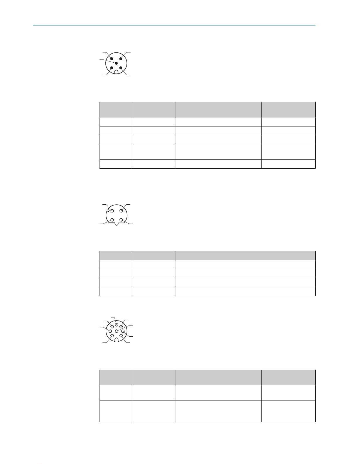
PWR connection
1
4 3
5
2
Figure 10: Male connector, M12, 5-pin, A-coded
Table 3: Pin assignment for PWR connection
Contact Identifier Description Wire color, part num‐
ber 2095733
1 Vs Supply voltage: +10 ... +30VDC Brown
2 - Reserved White
3 GND Supply voltage: 0V Blue
4 IN8/OUT8 Digital input 8: Set all counters to 0
(reset)
Black
5 - Reserved Gray
1) Data only valid when using the specified connecting cable with flying leads, which is available as an
accessory
Ethernet connection
1
43
2
Figure 11: M12 female connector, 4-pin, D-coded
Table 4: Pin assignment for Ethernet connection
Contact Identifier Description
1 TX+ Sender+
2 RX+ Receiver+
3 TX- Sender-
4 RX- Receiver-
I/O connection
1
7
2
6
3
4
5
8
Figure 12: Female connector, M12, 8-pin, A-coded
Table 5: Pin assignment for I/O connection
Contact Identifier Description Wire color part no.
6036155
1 IN1/OUT1 Digital output 1: Room capacity
reached (traffic light: red)
White
2 IN2/OUT2 Digital output 2: Room capacity
warning threshold reached (traffic
light: yellow)
Brown
6 ELECTRICAL INSTALLATION
20 O P E R A T I N G I N S T R U C T I O N S | MRS1000 PeopleCounter 8025783/1GI8/2022-09-14 | SICK
Subject to change without notice
Other manuals for MRS1000
4
Table of contents
Popular Cash Counter manuals by other brands


TSUJI ELECTRONICS
TSUJI ELECTRONICS NCT08-01B user manual

Nautilus Hyosung
Nautilus Hyosung MONiMAX7600DA Operator's manual

Polanik
Polanik T2-LB14 Assembly manual

Met One Instruments
Met One Instruments GT-521S manual

Opkon
Opkon OP-CN4 user guide

Arrow International
Arrow International PrecisionCounter 500 Service manual


