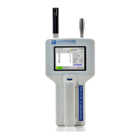
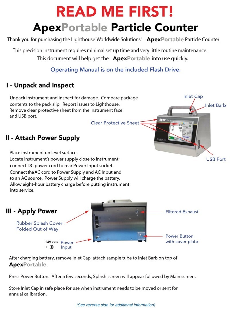
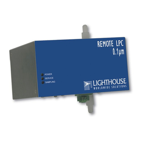
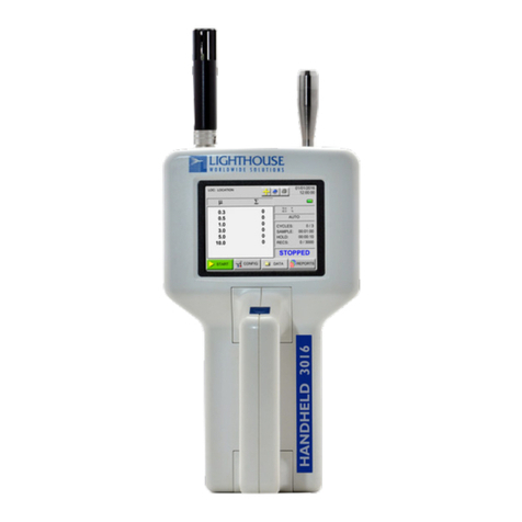
Lighthouse SOLAIR 2010+ User manual


00

Lighthouse Worldwide Solutions
SOLAIR 2010+, 3010+ Airborne Particle Counter
Operating Manual

Copyright © 2005 - 2009 by Lighthouse Worldwide Solutions. All rights reserved. No part of
this document may be reproduced by any means except as permitted in writing by Lighthouse
Worldwide Solutions.
The information contained herein constitutes valuable trade secrets of Lighthouse Worldwide
Solutions. You are not permitted to disclose or allow to be disclosed such information except as
permitted in writing by Lighthouse Worldwide Solutions.
The information contained herein is subject to change without notice. Lighthouse Worldwide
Solutions is not responsible for any damages arising out of your use of the LMS program.
SOLAIR™ and LMS™ are trademarks of Lighthouse Worldwide Solutions.
Microsoft®, Microsoft Windows™, and Excel™ are trademarks of Microsoft Corporation.
LWS Part Number: 248083218-1 Rev 5

EU DECLARATION OF CONFORMITY
Manufacturer’s Name: Lighthouse Worldwide Solutions, Inc.
Manufacturer’s Address: Lighthouse Worldwide Solutions, Inc.
1221 Disk Drive
Medford, OR 97501 USA
Declares that the product:
Product Name: Portable Airborne Particle Counter
Model Number(s): SOLAIR 2010+, 3010+
Conforms to the following Product Specifications:
SAFETY EN61010-1:2001 Safety Requirements for Electrical Equipment for
Measurement, Control, and Laboratory Use Part 1:
General Requirements IEC 61010-1:2000
Safety Requirements for Electrical Equipment for
Measurement, Control and Laboratory Use, Part 1:
General Requirements
LASER SAFETY Guidance on Laser Products: Conforms to FDA 21 CFR
Chapter 1 Subchapter 1
EMC EN61326 Electrical Equipment for Measurement, Control and
Laboratory Use EMC Requirements Part 1: General
Requirements Includes Amendment A1:1998; IEC
61326:1997 + A1:1998
UL 61010A-1 - UL Standard for Safety Electrical Equipment for Laboratory Use; Part 1: General Requirements
Replaces UL 3101-1
Supplementary information
The product herewith complies with the requirements of the Low Voltage Directive 73/23/EEC amended by
Directive 93/68/EEC and the EMC Directive 89/336/EEC amended by Directive 93/68/EEC and carries the
CE marking accordingly.
William Shade - V.P. Engineering
Fremont, CA. March 7, 2008
CAN/CSA C22.2
No. 1010.1-1992
IEC 60825-1 Am. 2
IEC 60601-2-22
(Laser Notice 50)


00
248083218-1 Rev 5 t-i
Table of Contents
About this Manual
Text Conventions ................................................................................................................ i
Additional Help ................................................................................................................... i
Chapter 1 Introduction
Overview ........................................................................................................................ 1-1
Description ..................................................................................................................... 1-2
SOLAIR 2010+ Specifications ...................................................................................... 1-3
SOLAIR 3010+ Specifications ...................................................................................... 1-4
Chapter 2 Unpacking, Inspecting and Installation
Initial Inspection ............................................................................................................ 2-1
Shipping Instructions ..................................................................................................... 2-1
Accessories .................................................................................................................... 2-2
Installation ..................................................................................................................... 2-3
Connecting Power .............................................................................................. 2-3
Installing the Battery .......................................................................................... 2-4
Removing the Battery ........................................................................................ 2-6
Connecting Isokinetic Probe .............................................................................. 2-6
Loading Printer Paper ........................................................................................ 2-8
Connecting an Analog Sensor .......................................................................... 2-11
Connecting an External Peripheral Device ...................................................... 2-11
Connecting to an External Computer or Facility Management System .......... 2-11
Chapter 3 Operation
Using the Instrument for the First Time ........................................................................ 3-1
Touch Screen Overview ................................................................................................. 3-2
Menu Map .......................................................................................................... 3-3
MAIN Screen ................................................................................................................. 3-3
LOCATION Selection ....................................................................................... 3-8
Changing Locations ............................................................................... 3-8
Locations and AUTO Mode .................................................................. 3-9
Zoomed Data View ............................................................................................ 3-9

Lighthouse SOLAIR 2010+, 3010+ Operating Manual
t-ii 248083218-1 Rev 5
Viewing Two Columns of Data ........................................................... 3-11
Viewing One Column of Data ............................................................. 3-12
CFG (Configuration) Screen ........................................................................................ 3-13
DATA SETUP ............................................................................................................. 3-14
Particle Channels ............................................................................................. 3-14
Analog Channels .............................................................................................. 3-16
Analog Data Display ............................................................................ 3-18
Zoomed Analog Data Display ............................................................. 3-18
SAMPLE .......................................................................................................... 3-19
SETTINGS ....................................................................................................... 3-22
COUNT MODE ................................................................................... 3-22
PARTICLE DISPLAY ........................................................................ 3-23
ALARM ........................................................................................................... 3-24
Alarm Threshold .................................................................................. 3-24
Alarm Acknowledge ............................................................................ 3-26
CLEAR BUFFER ............................................................................................ 3-26
DEVICE SETUP .......................................................................................................... 3-27
CLOCK ............................................................................................................ 3-27
OPTIONS ......................................................................................................... 3-29
CONTRAST ADJUST ........................................................................ 3-30
AUDIBLE BEEP ADJUST ................................................................. 3-30
ALIGN TOUCH SCREEN .................................................................. 3-30
Final Alignment Screen ....................................................................... 3-32
AUTOSTART MODE ......................................................................... 3-33
DiffCuml on Zoom .............................................................................. 3-33
ONE CHANNEL ................................................................................. 3-33
ONE SECOND REALTIME MODBUS OUTPUT ........................... 3-34
5 Second Startup .................................................................................. 3-34
COMM ADDRESS .......................................................................................... 3-35
LOCATION ..................................................................................................... 3-36
SECURITY ...................................................................................................... 3-37
POWER ON PASSWORD .................................................................. 3-38
CONFIGURATION PASSWORD ...................................................... 3-39
PRINT SETUP ................................................................................................. 3-39
Trouble Shooting the Printer ........................................................................................ 3-41
Possible Causes for No Print: .......................................................................... 3-41
Possible Causes for not printing straight: ........................................................ 3-42
SERVICE ......................................................................................................... 3-43
Data View Buffer Screen ............................................................................................. 3-43
Analog Data ......................................................................................... 3-46
Printing Data View Buffer reports ............................................................................... 3-46
Print Record ......................................................................................... 3-47
Print Range ...................................................................................................... 3-47
PRINT RECORD ............................................................................................. 3-48
PRINT RANGE (BUFFER Report) ................................................................ 3-49
Printing Buffer Report ......................................................................... 3-50


Table of Contents
248083218-1 Rev 5 t-iii
REPORTS .................................................................................................................... 3-53
Setting up Counter to Run Reports .................................................................. 3-57
Printing a Report .............................................................................................. 3-58
Report Requirements ....................................................................................... 3-59
Fed Std 209E (feet) .............................................................................. 3-59
Fed Std 209E (metric) .......................................................................... 3-60
ISO 14644-1 ......................................................................................... 3-60
EU GMP .............................................................................................. 3-60
Sample Printouts of Standard Reports ................................................. 3-61
Power Shutdown Levels .............................................................................................. 3-65
Chapter 4 Setting up the Counter
Analog Sensors .............................................................................................................. 4-1
Analog Setup ...................................................................................................... 4-2
Peripheral Interface Connector ...................................................................................... 4-5
Using Report Parameters ............................................................................................... 4-5
Basic Requirements ....................................................................................................... 4-6
Fed Std 209E (feet) ............................................................................................ 4-6
Fed Std 209E (metric) ........................................................................................ 4-6
ISO 14644-1 ....................................................................................................... 4-7
EU GMP ............................................................................................................ 4-7
Chapter 5 Programming
General Information ....................................................................................................... 5-1
Communicating with the Instrument ............................................................................. 5-1
RS-232/485 IN Port ........................................................................................... 5-2
RS-485 OUT Port .............................................................................................. 5-3
RS-232 Communications ................................................................................... 5-3
RS-485 Communications ................................................................................... 5-3
Configuring with the MODBUS Protocol ..................................................................... 5-4
Setting the Real Time Clock .............................................................................. 5-4
Changing the Default Instrument Parameters .................................................... 5-5
Running the Instrument ................................................................................................. 5-6
MANUAL Counting Mode ................................................................................ 5-7
AUTOMATIC Counting Mode ......................................................................... 5-8
Chapter 6 Maintenance Procedures
Introduction .................................................................................................................... 6-1
Safety ............................................................................................................................. 6-1
Maintenance ................................................................................................................... 6-1
Calibration ......................................................................................................... 6-1
Cleaning ............................................................................................................. 6-1

Lighthouse SOLAIR 2010+, 3010+ Operating Manual
t-iv 248083218-1 Rev 5
Purge Count Test ............................................................................................... 6-1
Troubleshooting ................................................................................................. 6-2
Appendix A Default Settings
Default Settings for SOLAIR Particle Counters ........................................................... A-1
Appendix B MODBUS Register Map v1.45
COMM Settings ............................................................................................................. B-1
Supported MODBUS Commands .................................................................................. B-1
Register Map .................................................................................................................. B-2
Sensor Settings Registers ................................................................................... B-2
Device Status ..................................................................................................... B-5
Command Register ........................................................................................................ B-7
Data and Alarm Registers .............................................................................................. B-9
Data and Alarm Enable Registers ...................................................................... B-9
Enable Alarming for a Channel ....................................................................... B-10
Threshold Setup Registers ............................................................................... B-11
Setting the Alarm Threshold Value ................................................................. B-12
Data Registers .............................................................................................................. B-13
Device Status Word (30007 - 30008) .............................................................. B-15
Valid Data in Channels (30073 - 30076) ......................................................... B-15
Data Type Registers ......................................................................................... B-16
Data Units Registers ........................................................................................ B-17
Appendix C MODBUS - Real Time Flow & Laser Current
Required Equipment and Software ................................................................................ C-1
Procedure for Computer to Instrument, only ..................................................... C-1
Appendix D Limited Warranty
Limitation Of Warranties: ..................................................................... D-1
Warranty Of Repairs After Initial Two (2) Year Warranty: ................. D-1
Index

00
248083218-1 Rev 5 i
About this Manual
This manual describes the detailed operation and use of the Lighthouse
SOLAIR 2010+ & 3010+Airborne Particle Counters.
Text
Conventions
The following typefaces have the following meanings:
Note: A note appears in
the sidebar to give extra
information regarding a
feature or suggestion
italics Represents information not to be typed
or interpreted literally. For example, file
represents a file name. Manual titles are
also displayed in italics.
WARNING: A
warning appears in a
paragraph like this and
warns that doing
something incorrectly
could result in personal
injury, damage to the
instrument or loss of
data.
boldface Introduces or emphasizes a term.
Courier font Indicates command syntax or text
displayed by the diagnostic terminal.
Bold Courier Indicates commands and information that
the user types. The user can enter
uppercase or lowercase letters; in this
manual, commands are shown in
uppercase.
Helvetica Italics Indicates a comment on a command or
text output.
Hexadecimal numbers are shown with the word "hex" or with a small
"h" following the digits. For example:
hex 0D
0Dh
Additional
Help
For more information about the Lighthouse SOLAIR 2010+ or 3010+
Airborne Particle Counter, contact Lighthouse Worldwide Solutions:
(800) 945-5905 Sales and Service
(510) 438-0500 Outside of USA
www.golighthouse.com

Lighthouse SOLAIR 2010+, 3010+ Operating Manual
ii 248083218-1 Rev 5

00
248083218-1 Rev 5 1-1
1Introduction
Overview This operating manual describes how to use the Lighthouse SOLAIR
2010+ and 3010+.
The model number signifies the minimum particle size measured by the
instrument. The number 2010 indicates a 0.2μm and 3010 indicates a
0.3 Pm minimum channel size at 0.1 CFM.
These SOLAIR instruments have six particle-size channels, up to four
environmental sensor channels, color touch screen interface, built-in
thermal printer and a rechargeable battery.
Note: For lists of the
standard channel sizes
available for each SOLAIR
model, see the SOLAIR
Specifications section in
this chapter.
All SOLAIR instruments contain a microprocessor that controls all of
the instruments’ functions. Count data is displayed in cumulative or
differential mode as raw data or normalized in particles per cubic foot
or per cubic meter.
Both models use the ELITE™ laser-diode light source and collection
optics for particle detection. Particles scatter light from the laser diode
and the collection optics collect and focus the light onto a photo diode
that converts the bursts of light into electrical pulses. The pulse height
is a measure of particle size. Pulses are counted and their amplitude is
measured for particle sizing. Results are displayed as particle counts in
the specified size channel.
Figure 1-1 SOLAIR 2010+ and 3010+

Lighthouse SOLAIR 2010+, 3010+ Operating Manual
1-2 248083218-1 Rev 5
Description Utilizing a large, touch screen interface, instruments in the SOLAIR
family are easy to configure and operate. Offering a sensitivity of 0.2μ
and 0.3μm at a flow rate of 0.1 CFM (2.83 LPM), the SOLAIR 2010+
and 3010+ have a wide dynamic range of particle sizes up to 25.0μm.
Both instruments store up to 3000 data records from up to 6 particle
count channels and 4 environmental sensors. All data can be quickly
and reliably downloaded to a computer or printed to its printer.
Instruments in the SOLAIR family allow you to:
• Set sampling and hold times.
• Configure the number of samples taken in a single location.
• Connect up to 4 environmental sensors.
• Print reports based on Federal Standard 209E (ft3), Federal
Standard 209E (m3), EU GMP (if unit has 0.5μ and 5.0μ channels)
and ISO 146441-1.
• Save data for historical data review.
• Print graphs and data tables using the included data transfer
software
When the instrument Calibration date expires, the Service LED will turn
on and stay on during sampling until the instrument is calibrated.
The manufacturer recommends that your Lighthouse instrument be
calibrated annually by a Certified Lighthouse Service Provider to ensure
that it continues to perform within specification.

Introduction
248083218-1 Rev 5 1-3
SOLAIR 2010+
Specifications
Size Range 0.2 - 10.0 μm
Channel Thresholds Standard: 0.2, 0.3, 0.5, 0.7, 1.0, 2.0 μm
Flow Rate 0.1 CFM (2.83 LPM)
Counting Efficiency 50% (per JIS)
Light Source ELITE™ Laser diode
Zero Count Level <1 count/5 minutes (per JIS)
Calibration NIST Traceable, per ISO 21501-4
Count Modes Concentration, manual, automatic, beep
Data Storage Up to 3000 sample records (particle data with
environmental, location and time data)
Communication Modes RS232 via RJ-45 to PC, RS485/MODBUS
Supporting Software LMS XChange Data Transfer Software; LMS
Express, Express RT+, LMSNet
Environmental Sensors Optional (up to 4): Temperature, Relative
Humidity, Air Velocity, Differential Pressure
Touch Screen Display Color, 5.7" (14.47 cm), 320x240
Printer Thermal printer
Reports FS-209E (ft), FS-209E (m), ISO 14644-1 and EU
GMP
Enclosure Stainless steel
Sample Output Internally filtered to HEPA standards (>99.997%
@ 0.2μm)
Vacuum Source Internal pump, flow controlled
Power 100-240 VAC, 50-60Hz
Battery Li-ion, removable & rechargeable
Dimensions 12.5"(L) x 8.0"(W) x 8.75" (H) [31.75 x 20.32 x
22.23 cm]
Weight Without battery - 15.0 lbs (6.82 kg)
with battery: 17.0 lbs (7.73 kg)
Operating Temp/RH 50° F to 104° F (10° C to 40° C) / 20% to 95%
non-condensing
Storage Temp/RH 14° F to 122° F (-10° C to 50° C) / Up to 98%
non-condensing
Table 1-1 2010+ Specifications

Lighthouse SOLAIR 2010+, 3010+ Operating Manual
1-4 248083218-1 Rev 5
SOLAIR 3010+
Specifications
Size Range 0.3 - 25.0 μm
Channel Thresholds Standard: 0.3, 0.5, 1.0, 3.0, 5.0, 10.0 μm
Flow Rate 0.1 CFM (2.83 LPM)
Counting Efficiency 50% (per JIS)
Light Source ELITE™ Laser diode
Zero Count Level <1 count/5 minutes (per JIS)
Calibration NIST Traceable, per ISO 21501-4
Count Modes Concentration, manual, automatic, beep
Data Storage Up to 3000 sample records (particle data with
environmental, location and time data)
Communication Modes RS232 via RJ-45 to PC, RS485/MODBUS
Supporting Software LMS XChange Data Transfer Software; LMS
Express, Express RT+, LMSNet
Environmental Sensors Optional (up to 4): Temperature, Relative
Humidity, Air Velocity, Differential Pressure
Touch Screen Display Color, 5.7" (14.47 cm), 320x240
Printer Thermal printer
Reports FS-209E (ft), FS-209E (m), ISO 14644-1 and EU
GMP
Enclosure Stainless steel
Sample Output Internally filtered to HEPA standards (>99.997%
@ 0.3μm)
Vacuum Source Internal pump, flow controlled
Power 100-240 VAC, 50-60Hz
Battery Li-ion, removable & rechargeable
Dimensions 12.5"(L) x 8.0"(W) x 8.75" (H) [31.75 x 20.32 x
22.23 cm]
Weight Without battery - 15.0 lbs (6.82 kg)
with battery: 17.0 lbs (7.73 kg)
Operating Temp/RH 50° F to 104° F (10° C to 40° C) / 20% to 95%
non-condensing
Storage Temp/RH 14° F to 122° F (-10° C to 50° C) / Up to 98%
non-condensing
Table 1-2 3010+ Specifications

00
248083218-1 Rev 5 2-1
2Unpacking, Inspecting
and Installation
Initial
Inspection
The instrument is thoroughly inspected and tested at the factory and is
ready for use upon receipt. When received, inspect the shipping carton
for damage. If the carton is damaged, notify the shipper immediately.
If the carton appears to be undamaged, open it carefully and inspect the
instrument for broken parts, scratches, dents, or other damage before
using.
Verify the contents of the package against the included shipping list and
contact your Sales Engineer or Lighthouse Worldwide Solutions if
there are any discrepancies.
WARNING: Always
remove the battery prior
to shipping the
instrument.
Keep the carton and all packing material for reshipment for the
instrument’s annual calibration.
Shipping
Instructions
Should it become necessary to return the unit to the factory for any
reason, contact Lighthouse Customer Service or visit our website,
www.golighthouse.com/rma, and obtain a Return Merchandise
Authorization (RMA) number. Reference this number on all shipping
documentation and purchase orders. After receipt of the RMA number,
follow the shipping instructions below:

Lighthouse SOLAIR 2010+, 3010+ Operating Manual
2-2 248083218-1 Rev 5
WARNING:
If the instrument is
damaged during a
return shipment due
to inadequate user
packing, the warranty
may be voided and
may result in
additional repairs
being billed to the
customer.
1. Use the original container, nozzle caps and packing materials
whenever possible. Remove any instrument battery and package it
to ship separately - refer to www.golighthouse.com/rma for detailed
instructions. Remove attachments, such as TRH or Isokinetic
probes, and package to prevent physical and ESD damage.
2. If the original container and packing materials are not available,
wrap the unit in "bubble pack", surround with shock-absorbent
material and place in a double-wall carton - the instrument should
not rattle around when the carton is vigorously shaken. If the
instrument is damaged during shipment due to inadequate user
packing, the warranty may be voided and may result in additional
repairs being billed to customer. You may contact Lighthouse to
purchase a replacement shipping container and nozzle caps.
3. Seal container or carton securely. Mark "FRAGILE" and write the
Return Merchandise Authorization (RMA) number on any
unmarked corner.
4. Return the instrument to the address provided by your Lighthouse
representative or the RMA website.
Accessories Several accessories may be ordered to tailor the instrument to your
needs. Some are optional and some are standard with each instrument.
•Temp/RH Wand (optional) - plugs into the instrument’s rear panel.
The 4-20mA probe monitors relative humidity (0% to 100%) and
temperature (0° to 150° F or -17.8° to 65.6° C). Results are
displayed, printed (if printer is available) and can be downloaded to
the LMS XChange software for backing up and historical data
review.
•Air Velocity Probe (optional) - plugs into the instrument’s rear
panel. The probe monitors air velocity up to 200 feet/minute (1.016
m/sec). Results are displayed, printed (if printer is available) and
can be downloaded to the LMS XChange software for backing up
and historical data review.
•Differential Pressure Sensor (optional) - plugs into the
instrument’s rear panel. Monitors range from 0 - 0.5"H2O (124.5
Pa). Results are displayed, printed (if printer is available) and can
be downloaded to the LMS XChange software for backing up and
historical data review.
•Isokinetic Sampling Probe (standard) - for use in unidirectional
air flow to maximize correlation between counts and actual
particle-size distribution. Can also be hand-held for spot location

Unpacking, Inspecting and Installation
248083218-1 Rev 5 2-3
particle counting.
•Filter Scanning Probe (optional) - for scanning for leaks in filter
assemblies.
• Shipping Case with Wheels (optional)
•Internal Printer
•Printer Paper (2 rolls)
•Cleanroom Printer Paper (optional, must be ordered in quantity
of 10 or more)
• Validation Documentation (optional)
•Li-Ion Battery, removable and rechargeable
• External Battery Charger (optional)
• Cleanroom Cart (optional)
• USB-Serial Adapter for laptops that have only a USB port and do
not have a 9-pin serial port for communications.
•LMS Express software, a data analysis software tool - contact
your Sales Engineer for specific information on this product.
Installation Connecting Power
The power input is 100-240VAC, 50-60Hz. A power cable is included
with your SOLAIR. The power switch is located on the front of the
unit.
Lighthouse recommends using protected power to prevent exposing the
instrument to voltage spikes. Using an uninterruptible power supply
when the SOLAIR is kept in a stationary location will help prevent
damage to the instrument or loss of data in the event of a power outage.

Lighthouse SOLAIR 2010+, 3010+ Operating Manual
2-4 248083218-1 Rev 5
Installing the Battery
The SOLAIR 2010+, 3010+ comes with a removable, rechargeable Li-
ion battery.
The battery needs to be installed if the instrument will be used for
portable operation. Initially, the battery may not have a full charge. To
charge the battery once it is installed, plug the unit into an AC power
source and turn on the main power switch located on the front of the
unit.
Note: To recharge the
battery inside the unit, plug
in the AC power source
and turn the front power
switch on.
To install the battery, first make sure that power switch on the front of
the unit is in the OFF position. Then follow these instructions:
5. Open the battery compartment door by turning the screw lock
counterclockwise.
Figure 2-1 Battery compartment door
This manual suits for next models
1
Table of contents
Other Lighthouse Cash Counter manuals

Lighthouse
Lighthouse RLPC 0.1m User manual

Lighthouse
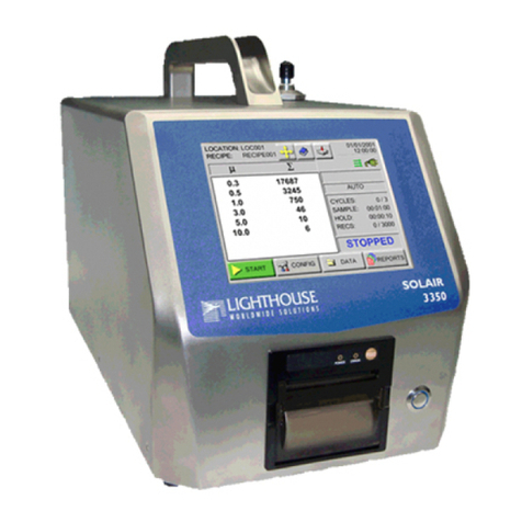
Lighthouse SOLAIR 3350 User manual

Lighthouse
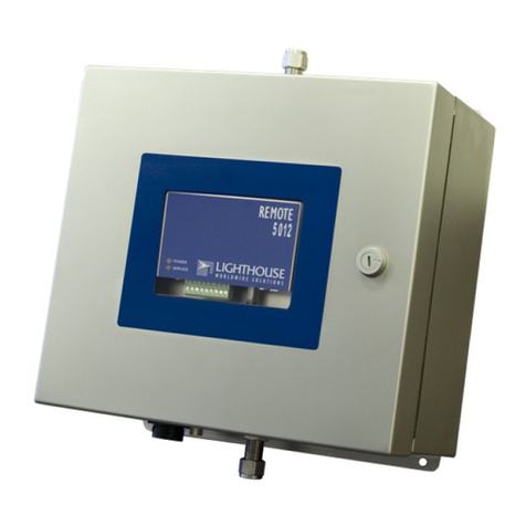
Lighthouse REMOTE 3104P User manual

Lighthouse
Lighthouse Remote 3014PN User manual

Lighthouse
Lighthouse NanoCount 30+ User manual

Lighthouse
Lighthouse ApexPortable Manual

Lighthouse
Lighthouse REMOTE-2 PN Series User manual

Lighthouse
Lighthouse SOLAIR 1001 + User manual

Lighthouse
Lighthouse ApexPortable Series User manual

Lighthouse
Lighthouse ApexZ Series User manual