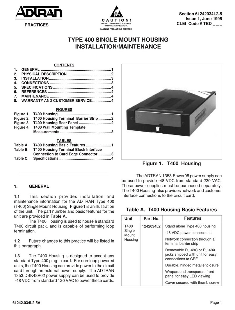
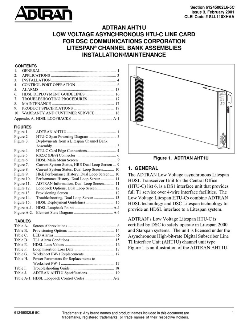
ADTRAN BR1/10 E1 Instruction Manual

1Section 61150279L1-5, Issue 161150279L1-5A
1. GENERAL
This practice provides installation and maintenance
procedures for the ADTRAN BR1/10 E1 LIU.
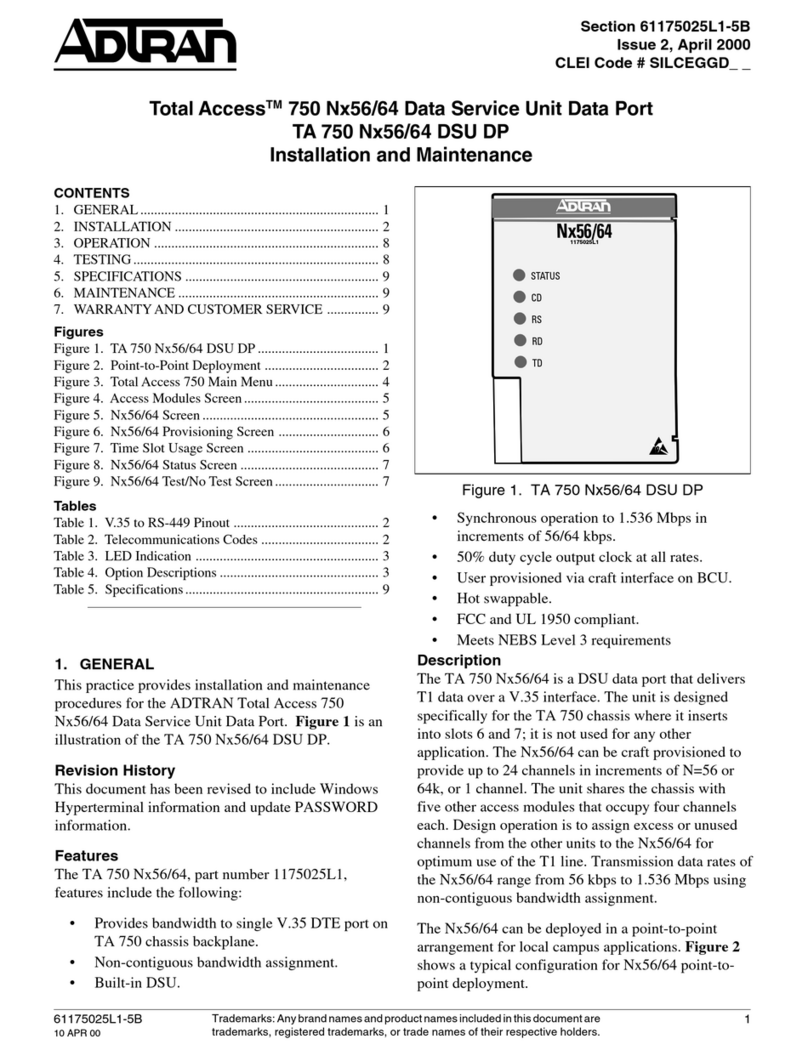
Figure␣ 1 is an illustration of the BR1/10 E1 LIU.
Revision History
This is the initial release of this document. Future
revisions will be described in this subsection.
Features
The BR1/10 E1 LIU (E1 LIU), part number
1150279L1, includes the following features:
• Common Channel Signal (CCS) framing formats.
• AMI and HBD3 Line Coding.
• Local and remote loopback for E1 interface.
• BRI test access control. (U-BR1TE mode only)
• Front panel bantam jack for DS0 logic tester
access. (U-BR1TE mode only)
• Front panel DB-9 for DS0 logic tester clock
input. (U-BR1TE mode only)
Section 61150279L1-5A
Issue 1, March 2000
CLEI Code # N/A
BR1/10 E1 LIU
BR1/10 E1 Line Interface Unit
Installation and Maintenance
General Description
The E1 LIU is a common module plug-in unit used in
the ADTRAN BR1/10 channel bank as the interface
between the channel bank and the E1 line. The BR1/
10 can be used in Frame Relay Multiplex
configurations to support multiple applications. The
BR1/10 functions as an ISDN channel bank and
provides 10 standard 2B+D subscriber lines. In the
Frame Relay Multiplex configuration, the BR1/10
functions as a statistical multiplexer, concentrating up
to 10 high speed SDSL subscriber lines into a single
E1 carrier facility.
The E1 LIU provides data formatting, line encoding,
and timing recovery and generation for BRI and E1
transmission. Two 10-position rotary switches allow
for selection of BRI tests, a dual bantam jack provides
test access, and a DB-9 furnishes both an 8 kHz and a
64 kHz clock for the DS0 logic test set. Option
selections for E1 LIU functions are selected using the
DIP switch on the associated BR1/10 E1 BCU.
The BR1/10 can be used with the ADTRAN
FramePort products to deliver IDSL and SDSL
Trademarks: Any brand names and product names included in this document are
trademarks, registered trademarks, or trade names of their respective holders.
Figure 1. BR1/10 E1 LIU
5
4
3
2
1
9
8
76
ADR3
ADR2
AD
R1
NT1
LPTX
LPBX
AD
R6
AD
R5
ADR4
10
CRTX
T
E
S
T
IN
T
E
S
T
OUT
E1 LIU
1150279L1
CONTENTS
1. GENERAL ............................................................1
2. INSTALLATION..................................................2
3. TESTING ..............................................................3
4. SPECIFICATIONS ...............................................6
5. MAINTENANCE..................................................6
6. WARRANTY AND CUSTOMER SERVICE......6
FIGURES
Figure 1. BR1/10 E1 LIU..........................................1
Figure 2. BR1/10 E1 LIU and BCU..........................3
Figure 3. DB-9 Connector.........................................3
TABLES
Table 1. Rotary Test Switch Options ........................3
Table 2. E1 BCU Test DIP Switch............................ 4
Table 3. BR1/10 E1 LIU Specifications ...................6

2 Section 61150279L1-5, Issue 1 61150279L1-5A
services from 64 kbps to 1.024 Mbps. In the
statistical mode of operation, virtual circuits are
established between the BR1/10 and a frame relay
switch or router over an un-channelized E1 Facility.
The E1 LIU initiates both local and remote loopbacks
as commanded by the associated E1 BCU. Detailed
test processes are described in Section 3, Testing.
2. INSTALLATION
After unpacking the unit inspect it for damage. If
damage is noted file a claim with the carrier then
contact ADTRAN. See Warranty and Customer
Service.
CAUTION
Do not insert the E1 LIU into a powered-up
backplane unless the E1 BCU is already
inserted.
The E1 LIU plugs directly into the common card area
of a BR1/10 chassis in the LIU slot. To install, hold
the unit by the front panel while supporting the bottom
side. Align the unit to the LIU slot guides. Slide the
unit into the shelf ensuring the edge connector inserts
firmly into the backplane. Lock the unit in place by
pushing in on the lock lever.
Power Cycling
If the E1 LIU is inserted into a powered-up channel
bank, power to the channel bank must be cycled to
cause reinitialization of channel bank elements. To
cycle power, remove and reinsert either the front panel
fuse on the associated PAU, or the -48 V input fuse on
the channel bank backplane.
Optioning
The E1 LIU does not require DIP switch settings.
Instead, the multi-position DIP switch on the E1 BCU
circuit board (SW3) provides the necessary option
settings for the channel bank common cards. These
options must be selected prior to card insertion into
the channel bank. Refer to E1 BCU I&M Practice,
ADTRAN part number 61150280L1-5, for additional
information.
Connections
All input and output to the E1 LIU is made through
the backplane. No additional backplane wiring is
necessary for design operation.
Front panel Features
The E1 LIU front panel components work in
conjunction with the E1 BCU to monitor status and to
initiate BRI testing and E1 loopback testing. On the
E1 LIU, two 10-position rotary switches work
together to perform tests or monitor channel bank
status. Access to individual units is provided through
front panel bantam jacks, while the DB-9 provides the
necessary clock output required by standard DS0 logic
test equipment. Figure 2 is an illustration of the E1
LIU and E1 BCU.
NOTE
Front panel rotary switches and bantam test
access apply to U-BR1TE application of BR1/
10. In FramePort application, rotary switches
have no effect, and use of bantam test access
will cause disruption of service.
DSL Channel Selection Switch
(U-BR1TE Mode Only)
The DSL switch selects individual channel positions
for monitoring and BRI testing. Labeled 1 through 10,
the switch selects the corresponding channel unit.
When selected, the individual channel unit’s STATUS
LED will Flash red/green for about 3 seconds to
acknowledge selection. The LEDs on the E1 BCU
then display current status of the selected channel unit.
Loopback Address Switch (U-BR1TE mode only)
The Address switch selects the local test to be
performed for the designated channel unit. Tests
include loopback for the NT-1 and up to six ISDN
devices in the customer direction. Test transmission
include the following:
• Test pattern to carrier.
• Test pattern to loop interface.
• Local bilateral loopback.
• Local performance monitoring.
Table 1 shows the E1 LIU 10-position Address switch
options.
C A U T I O N !
SUBJECT TO ELECTROSTATIC DAMAGE
OR DECREASE IN RELIABILITY.
HANDLING PRECAUTIONS REQUIRED.

3Section 61150279L1-5, Issue 161150279L1-5A
Figure 2. BR1/10 E1 LIU and BCU
DB-9 Connector
The DB-9 female connector provides access to the
8␣ kHz and 64 kHz clock reference for DS0 logic test
equipment. Figure 3 illustrates the DB-9 connector.
3. TESTING
Although ISDN is designed to be tested from the CO
ISDN switch it may be necessary during fault
isolation or equipment malfunction to conduct remote
testing from the local E1 LIU. The E1 LIU provides
access for both E1 loopback and BRI testing.
E1 loopback testing has two loopback modes: local
loopback and remote loopback. E1 loopbacks include:
• Providing a loopback for the local E1 data
stream.
• Providing a loopback for the remote E1 data
stream.
Table 1. Rotary Test Switch Options
lebaLnoitpircseD
1RDA.ecived)tsrifeht(sihtfosserddA
2RDA.ecivedmaertsnwoddnocesehtfosserddA
3RDA.ecivedmaertsnwoddrihtehtfosserddA
4RDA.ecivedmaertsnwodhtruofehtfosserddA
5RDA.ecivedmaertsnwodhtfifehtfosserddA
6RDA.ecivedmaertsnwodhtxisehtfosserddA
KBPL saskcabpool2Bro1BlanoitceridibsecroF
.hctiwspidetalpecafUCBehtnodetceles
XTRC.noitceridreirracehtnitimsnartreirraC
XTPL.noitceridreirracehtnitimxnartpooL
1TN.1TNehtfosserddA
SW3
DB-9
Bantam jacks
DSL selection
Loopback address
E1 BCU test DIP switch
TEST pushbutton
Figure 3. DB-9 Connector
TEST
+5 V
GND
64 kHz
8 kHz
1
2
3
4
5
6
7
8
9
NOTE
Front panel rotary switches and bantam test access
apply to TDM U-BR1TE application of BR1/10. In
FramePort application, rotary switches have no
effect, and use of bantam test access will cause
disruption of service.

4 Section 61150279L1-5, Issue 1 61150279L1-5A
Test Access and Selection (U-BR1TE mode only)
The E1 LIU and E1 BCU allow access for standard
DS0 test sets. The E1 LIU provides test selection for
each individual U-BR1TE channel unit. The front
panel DIP switch on the BCU selects test types for
both E1 loopback and BRI tests. Table 2 describes E1
BCU DIP switch test selections.
When a U-BR1TE channel card is configured for D
channel operation it will respond to embedded
operation channel (eoc) loopbacks, including B1, B2,
and 2B+D. These loopbacks can be initiated from an
upstream device including the ISDN switch, another
U-BR1TE channel unit, or ISDN test equipment
developed for this purpose.
BRI testing provides test access for individual BR1/10
U-BR1TE channel units. The E1 LIU bantam jacks
accommodate standard DS0 logic testers such as the
TPI-108/109 RT II or the FIREBERD 4000/6000.
Selection for B1 or B2 is made on the E1 BCU front
panel DIP switch. The E1 LIU's rotary switches select
the designated channel and the desired test. Pressing
the TEST pushbutton on the E1 BCU front panel
initiates the test. This will turn the DS0-LB LED On.
Pressing the TEST button a second time terminates the
test as indicated by the DS0-LB LED going Off.
NOTE
Disengaging the bantam jacks will also
terminate tests.
E1 Loopback Testing
Loopback tests incorporate functions of the E1 LIU
and E1 BCU common cards in both the local and
remote channel banks. For simplicity of description
the term Channel Bank is used as a generic reference
to common cards.
CAUTION
E1 loopback tests are intrusive and will disrupt
service to the entire BR1/10 channel bank.
Local Loopback
A local loopback bridges the E1 line across the
receive pair to the transmit pair isolating the bank
from the E1 line. This allows for internal bank testing
and individual card testing, and provides a baseline for
E1 line testing.
To initiate local loopback, select LB ON and LOC on
the E1 BCU front panel DIP switch. This causes
outgoing transmitted data to loop back to the receiver
at the local BR1/10. During the test unframed All
Ones (A1S) are transmitted to the E1 network causing
the G.703 LED to turn On green. The E1 LOC LED
will also turn On indicating local loopback is in effect.
To terminate the test, position LB to OFF. The G.703
and E1 LOC LEDs turn Off indicating test
termination.
NOTE
When local loopback is invoked and the E1
BCU is configured for loop timing, the BR1/10
defaults to local timing.
Remote Loopback
Remote loopback bridges E2 transmit pair to receive
pair, causing incoming data to loopback to the
transmitter.
To initiate remote loopback, select REMOTE and LB
ON on the E1 BCU front panel.
In response, the remote E1 BCU will Flash its RMT
LED. RMT LED will turn On indicating successful
completion of the remote loopback.
To terminate the test, position LB to OFF. The local
channel bank returns to normal operation as indicated
by the RMT LED turning Off.
BR1 Testing (U-BR1TE mode only)
Local test access is provided to each of the installed
BR1/10 U-BR1TE channel units in the downstream
and upstream directions. The E1 LIU provides bantam
Table 2. E1 BCU Test DIP Switch
noitisoPnoitpircseD
NOBL
FFOBL
.skcabpool1EsetaitinI
.skcabpool1EsetanimreT
LACOL
ETOMER
1EehtnikcabpoollacollanretnisetaitinI
.maertsatad atad1EehtnikcabpooletomerasetaitinI
.maerts
1B
2B.gnitsetIRBroflennahc1BstceleS
.gnitsetIRBroflennahc2BstceleS

5Section 61150279L1-5, Issue 161150279L1-5A
jack BRI logic access, 8 kHz and 64 kHz clock
reference, selection of the desired channel unit (1-10),
and the desired test. When the 10 position rotary
switch is used to select a channel unit, the STATUS
LED on the selected unit will Flash red/green for
about 3 seconds then return to the current status. Refer
to U-BR1TE channel unit document, ADTRAN part
number 61150077L1-5, for additional STATUS LED
operation.
Loopback Test (ADR1-ADR6, NT1)
Loopbacks in the network-to-customer direction can
be initiated from either the ISDN switch or the E1
LIU. The downstream direction is automatically
selected based on the card position in the network. To
initiate a loopback, perform the following steps:
1. Insert the TX and RX plugs of the DS0 digital
test set into the bantam jacks on the LIU.
Connect the clock input to the DS0 digital test set
DB-9 connector on the LIU. Configure the test
set for Near Logic and 64 kbps.
2. Select the desired U-BR1TE channel unit using
the DSL switch on the LIU.
3. Select the desired loopback address on the LIU
(ADR1-ADR6, or NT1).
4. Select the desired bearer channel using B1/B2
DIP switch on the E1 BCU.
5. Press the TEST pushbutton to initiate the
loopback test. The DS0 LB status LED will turn
ON when the loopback is established to the
selected address. If the selected address does not
respond, the DS0 LB LED will remain OFF.
Observe the DS0 digital set for bit errors.
6. To terminate the loopback, press the TEST
pushbutton or remove the transmit bantam plug.
Upon deactivation of the test the DS0 LB LED
will turn OFF.
Loopback tests to additional network addresses can be
performed by changing to another address with the
Loopback Address switch (step 3). It is not necessary
to exit the test mode to select a new address.
If a new U-BR1TE channel unit is selected testing is
terminated. However, pressing the TEST pushbutton
will initiate the previous test arrangement on the new
address. To start from the beginning (ADR1) return to
step 2.
Point-to-Point Test, (CRTX, LPTX)
A point-to-point (straightaway) test can be performed
to either the U-interface (LPTX) or the E1 carrier
interface (CRTX). This test requires craft personnel at
the local and remote channel banks.
To initiate a point-to-point test using a DS0 digital test
set perform the following steps:
1. Insert the TX and RX bantam plugs of the DS0
digital test set into the jacks on the LIU. Connect
the clock input to the DS0 digital test set DB-9
connector on the LIU. Configure the test set for
Near Logic and 64 kbps.
2. Select the desired U-BR1TE channel unit using
the DSL switch on the LIU.
3. Select the desired test direction: LPTX or CRTX
on the LIU.
4. Select the desired bearer channel using B1/B2
DIP switch on the BCU.
5. Press the TEST pushbutton on the BCU to
initiate the test.
6. If the remote unit is a BR1/10 U-BR1TE channel
unit, perform Steps 1 through 4, choosing the
same front panel switch setting. Ensure both test
sets are configured for the same test pattern (511,
2047).
7. Observe the DS0 digital test set for bit errors.
8. To deactivate the loopback, press the TEST
pushbutton or remove the transmit bantam plug.
Upon deactivation of the test the DS0-LB LED
will go Off.
Local Loopback (LPBK)
A bilateral loopback can be initiated for any of the
BR1/10 U-BR1TE channel units for either bearer
channel. A local test pattern source is not required for
this test. To initiate a local loopback, perform the
following:
1. Select the desired U-BR1TE channel unit using
the DSL switch on the LIU.
2. Select LPBK on the Address switch on the LIU.
3. Select the desired bearer channel using B1/B2
DIP switch on the BCU.
4. Press the TEST pushbutton to initiate the test.
The DS0-LB LED will Flash once a second for
B1, or twice in succession for B2.
6 Section 61150279L1-5, Issue 1 61150279L1-5A
5. To deactivate the loopback press the TEST
pushbutton. Upon deactivation of the test the
DS0 LED will go Off.
Local Performance Monitoring
Performance monitoring of the local E1 carrier system
and the 2-wire U-interface of the ISDN data can be
performed from the front panel without interruption of
service to the customer. For this test, bearer channel
selection is not applicable and a test pattern source is
not required. To initiate local performance
monitoring, conduct the following:
1. Ensure a bantam plug is NOT inserted in the TX
jack on the E1 LIU.
2. Select the desired U-BR1TE channel unit using
the DSL switch on the LIU.
3. Select ADR1 on the LIU Address switch.
4. Press the TEST pushbutton to initiate the test.
The DS0-LB LED will turn ON.
5. The total number of CRC errors is
simultaneously displayed by the LP CRC and CR
CRC LEDs. The LEDs will Flash for more than 6
but less than 19 errors, and turn ON steady for
more than 20 errors.
4. SPECIFICATIONS
The specifications for the BR1/10 E1 LIU are listed in
Table␣ 3.
5. MAINTENANCE
The BR1/10 E1 LIU does not require routine
maintenance for normal operation.
ADTRAN does not recommend that repairs be
performed in the field. Repair services are obtained by
returning the defective unit to ADTRAN Customer
Service. See Warranty and Customer Service.
6. WARRANTY AND CUSTOMER SERVICE
ADTRAN will replace or repair this product within 10
years from the date of shipment if it does not meet its
published specifications or fails while in service (see
ADTRAN Carrier Network Equipment Warranty,
Repair, and Return Policy and Procedure, document
60000087-10A).
Contact Customer and Product Service (CAPS) prior
to returning equipment to ADTRAN.
For service, CAPS requests, or further information,
contact one of the following numbers:
ADTRAN Sales
Pricing and availability
(800) 827-0807
ADTRAN Technical Support
Presales Applications / Post-sale Technical Assistance
(800) 726-8663
Standard support hours:
Monday-Friday, 7 a.m. - 7 p.m. CST
Emergency support: 7 days/week, 24 hours/day
ADTRAN Repair/CAPS
Return for repair / upgrade
(256) 963-8722
Repair and Return Address:
ADTRAN, Inc.
CAPS
901 Explorer Boulevard
Huntsville, Alabama 35806-2807
Table 3. BR1/10 E1 LIU Specifications
latnemnorivnE
erutarepmeTgnitarepO C°07+otC°04- )F°851+otF°04-(
erutarepmeTegarotS C°58+otC°04- )F°581+otF°04-(
ytidimuHevitaleRgnisnednocnon%59
lacisyhP
snoisnemiD
thgieW
W"8/7xH"2/12xL"8/39
zO2.3
Table of contents
Other ADTRAN Computer Hardware manuals

ADTRAN
ADTRAN U-BR1TE User manual

ADTRAN
ADTRAN MX2820 User manual

ADTRAN
ADTRAN AHT1U Maintenance and service guide

ADTRAN
ADTRAN TRACER 6000 SERIES User manual

ADTRAN
ADTRAN T400 User manual

ADTRAN
ADTRAN ESU 120e User manual

ADTRAN
ADTRAN Total Access 750 Nx56/64 Instruction Manual

ADTRAN
ADTRAN 1200127L1 User manual
Popular Computer Hardware manuals by other brands

Alphacool
Alphacool NexXxoS GPX-A 280 M08 instruction manual

EKF
EKF SC1-ALLEGRO user guide

Renesas
Renesas M32182T2-PTC instruction manual

Linear Technology
Linear Technology LT6411 quick start guide

Freescale Semiconductor
Freescale Semiconductor FRDM-K64F quick start guide

Texas Instruments
Texas Instruments DS125RT410 manual