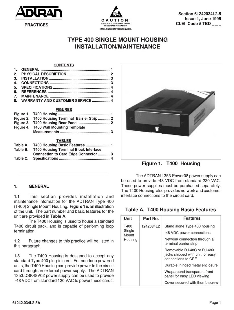
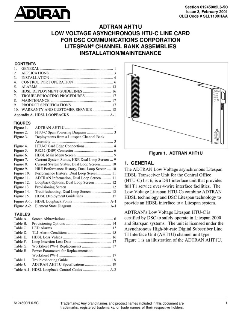
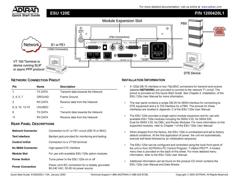
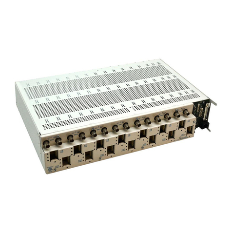
ADTRAN Total Access 750 Nx56/64 Instruction Manual

1Section 61175025L1-5, Issue 261175025L1-5B
10 APR 00
Section 61175025L1-5B
Issue 2, April 2000
CLEI Code # SILCEGGD_ _
Total AccessTM 750 Nx56/64 Data Service Unit Data Port
TA 750 Nx56/64 DSU DP
Installation and Maintenance
1. GENERAL
This practice provides installation and maintenance
procedures for the ADTRAN Total Access 750
Nx56/64 Data Service Unit Data Port. Figure 1 is an
illustration of the TA 750 Nx56/64 DSU DP.
Revision History
This document has been revised to include Windows
Hyperterminal information and update PASSWORD
information.
Features
The TA 750 Nx56/64, part number 1175025L1,
features include the following:
•Provides bandwidth to single V.35 DTE port on
TA 750 chassis backplane.
•Non-contiguous bandwidth assignment.
•Built-in DSU.
Figure 1. TA 750 Nx56/64 DSU DP
Trademarks: Any brand names and product names included in this document are
trademarks, registered trademarks, or trade names of their respective holders.
STATUS
CD
RS
RD
TD
Nx56/64
1175025L1
•Synchronous operation to 1.536 Mbps in
increments of 56/64 kbps.
•50% duty cycle output clock at all rates.
•User provisioned via craft interface on BCU.
•Hot swappable.
•FCC and UL 1950 compliant.
•Meets NEBS Level 3 requirements
Description
The TA 750 Nx56/64 is a DSU data port that delivers
T1 data over a V.35 interface. The unit is designed
specifically for the TA 750 chassis where it inserts
into slots 6 and 7; it is not used for any other
application. The Nx56/64 can be craft provisioned to
provide up to 24 channels in increments of N=56 or
64k, or 1 channel. The unit shares the chassis with
five other access modules that occupy four channels
each. Design operation is to assign excess or unused
channels from the other units to the Nx56/64 for
optimum use of the T1 line. Transmission data rates of
the Nx56/64 range from 56 kbps to 1.536 Mbps using
non-contiguous bandwidth assignment.
The Nx56/64 can be deployed in a point-to-point
arrangement for local campus applications. Figure 2
shows a typical configuration for Nx56/64 point-to-
point deployment.
CONTENTS
1. GENERAL ..................................................................... 1
2. INSTALLATION ........................................................... 2
3. OPERATION ................................................................. 8
4. TESTING ....................................................................... 8
5. SPECIFICATIONS ........................................................ 9
6. MAINTENANCE .......................................................... 9
7. WARRANTY AND CUSTOMER SERVICE ............... 9
Figures
Figure 1. TA 750 Nx56/64 DSU DP ................................... 1
Figure 2. Point-to-Point Deployment ................................. 2
Figure 3. Total Access 750 Main Menu .............................. 4
Figure 4. Access Modules Screen ....................................... 5
Figure 5. Nx56/64 Screen ................................................... 5
Figure 6. Nx56/64 Provisioning Screen ............................. 6
Figure 7. Time Slot Usage Screen ...................................... 6
Figure 8. Nx56/64 Status Screen ........................................ 7
Figure 9. Nx56/64 Test/No Test Screen.............................. 7
Tables
Table 1. V.35 to RS-449 Pinout .......................................... 2
Table 2. Telecommunications Codes .................................. 2
Table 3. LED Indication ..................................................... 3
Table 4. Option Descriptions .............................................. 3
Table 5. Specifications ........................................................ 9

2 Section 61175025L1-5, Issue 2 61175025L1-5B
10 APR 00
C A U T I O N
C A U T I O N
!
SUBJECT TO ELECTROSTATIC DAMAGE
OR DECREASE IN RELIABILITY.
HANDLING PRECAUTIONS REQUIRED.
The TA 750 Power Supply Unit (PSU) and Bank
Controller Unit (BCU) common modules provide both
power and provisioning for the Nx56/64. Provisioning
is screen menu driven via a DB-9 VT 100 interface on
the BCU. All wiring connections are built into the
TA 750 chassis backplane. External wiring
connections are not required.
Signal transmission of the Nx56/64 is through the
V.35 port on the TA 750 chassis backplane. For those
installations equipped with an RS-449 connection, a
V.35 to RS-449 adapter cable pinout is shown in
Table 1.
Table 1. V.35 to RS-449 Pinout
53.V944-SR
etoNemaN niP
oN
niP
oN emaNetoN
dnGmrF
dnGgiS
A
B
1
91
02
73
dnGmrF
dnGgiS
moCxR
moCxT
,02,91sniP
73dna
.detcennoc
toN
desU
STR
STC
RSD
DC
RTD
dnIllaC
C
D
E
F
H
J
7
9
21
31
STR
STC
RTD
RSD
otdepoolSTR
.STC
otdepoolRTD
.RSD
ADxT
ADxR
BDxT
BDxR
P
R
S
T
4
6
22
42
ADxT
ADxR
BDxT
BDxR
ACxTtxE
ACxRtxE
BCxTtxE
BCxRtxE
ACxT
BCxT
U
V
W
X
Y
AA
71
8
53
62
5
32
ACxTtxE
ACxRtxE
BCxTtxE
BCxRtxE
ACxT
BCxT
52
72
03
13
BSTR
BSTC
BRTD
BRSD
depoolBSTR
.BSTCot
depoolBRTD
.BRSDot
This device complies with Part 15 of the FCC rules.
Operation is subject to the following two conditions:
(1) This device may not cause harmful interference,
and (2) this device must accept any interference
received, including interference that may cause
undesired operation.
Changes or modifications not expressly approved by
ADTRAN could void the user's authority to operated
this equipment.
2. INSTALLATION
After unpacking the unit inspect it for damage. If
damage is noted, file a claim with the carrier then
contact ADTRAN Customer Service. See Warranty
and Customer Service.
The TA 750 Nx56/64 can only insert into slots 6 and 7
of the TA 750 chassis. To install, hold the unit by the
faceplate while supporting the bottom side. Align the
card edges with the guide grooves and insert in the
chassis until the edge connector seats firmly into the
backplane. Lock the unit in place by pressing in on the
locking lever.
Telecommunications Codes
This product is intended for installation in Restricted
Access Locations only and is intended to be installed
in equipment with a Type "B" or "E" installation code.
See Table 2.
Start-Up
The Nx56/64 is operational upon installation in an
active TA 750 chassis. When inserted, front panel
LEDs show an initialization sequence then provide
unit operational status. During initialization the
STATUS LED will turn On (red). After several
seconds the other LEDs will scroll several times then
all LEDs will remain steady showing current status of
the Nx56/64.
Router TA 750
TA 750 Router
V.35
T1
V.35
Figure 2. Point-to-Point Deployment
Code Input Output
PC C C
TC - X
TC A -
Table 2. Telecommunications Codes

3Section 61175025L1-5, Issue 261175025L1-5B
10 APR 00
LED Status
The Nx56/64 faceplate has five LEDs to show status
of the unit plus the condition of the transmit and
receive data interfaces. In normal operation all LEDs
are On (green). Refer to Table 3 for LED
descriptions.
Timing
The Nx56/64 obtains single source timing from the
BCU.
Configuration
There are no hardware options on the Nx56/64 circuit
board. All options are screen menu driven by the
BCU. Listed here are the default options:
Channels 4
Data Rate 64 kbps
DSR Normal
CTS Normal
CD Normal
DTE Tx Clk Auto
Refer to Table 4 for option descriptions.
Table 4. Option Descriptions
Configuration Description
# Of Channels ....... Selects the number of time slots (01 thru 24) for Nx56 64 kbps operation
RATE 56 64 .......... Selects the channel data rate of either 56 kbps or 64 kbps
56 .................................. Selects 56 kbps
64 .................................. Selects 64 kbps
DSR ...................... Controls the state of the DSR lead from the Nx56 64
NORMAL ..................... Causes DSR to follow DTR
FORCED ON ............... Causes DSR to be forced on and DTR ignored
CTS ....................... Controls the state of the CTS lead from the Nx56 64
NORMAL ..................... Causes CTS to follow RTS
FORCED ON ............... Causes CTS to be forced on and RTS ignored
CD ........................ Controls the state of the CD lead from the Nx56 64
NORMAL ..................... CD is active when loops are in sync and or when a T1 carrier is present
FORCED ON ............... Causes CD to be forced on always
DTE TX CLK ....... Selects the timing source for the transmit data clock
Internal Invert ............... Inverted form of the internal DTE TX CLK setting
AUTO ........................... Measures the delay between the DTE data and its clock and
automatically selects between INTERNAL and INT-INV
INTERNAL .................. Allows the Nx56 64 to provide transmit data clock
EXTERNAL ................. Derives DTE transmit clock from the DTE device
DELroloCnoitpircseD
SUTATS
:ffO
:deR
:neerG
:wolleY
rewoPoN
.mralAniknabroETDhtiwcnysfotuO
.ETDhtiwdezinorhcnyS
.evitcakcabpooL
DC
tceteDreirraC :ffO
:neerG
.atadevieceRrotimsnarTotsutats46/65xNsetacidnI
.atadevieceRrotimsnarTotydaertoN
.atadevieceRrotimsnarTotydaeR
SR
dneSottseuqeR :ffO
:neerG
.atadevieceRrotimsnarTotsutatsETDsetacidnI
.atadevieceRrotimsnarTotydaertoN
.atadevieceRrotimsnarTotydaeR
DR
ataDevieceR :ffO
:neerG
.ecafretniETDehtnonipataDevieceRehtfosutatssetacidnI
.krowten1TehtmorfdeviecergniebtonataD
.krowten1TehtmorfdeviecergniebsiataD
DT
ataDtimsnarT :ffO
:neerG
.ecafretniETDehtnonipataDtimsnarTehtfosutatssetacidnI
.ETDehtmorfdeviecergniebtonataD
.ETDehtmorfdeviecergniebsiataD
.ssergorpninoitazilaitinietacidnignillorcssDEL:etoN
Table 3. LED Indication

4 Section 61175025L1-5, Issue 2 61175025L1-5B
10 APR 00
Electronic Provisioning
The craft interface on the TA 750 BCU is used to
change default options and obtain access module
status through menu screens. To access the menu
screens, connect a VT 100 terminal or computer
running a terminal emulation program to the faceplate
craft interface ADMIN port using a standard male-to-
female RS-232 DB9 cable. Craft port settings are as
follows:
•9600 Baud
•No parity
•8 Data bits
•1 Stop bit
Windows Hyperterminal
Windows Hyperterminal can be used as a VT 100
terminal emulation program. Open Hyperterminal by
selecting PROGRAMS/ACCESSORIES/
HYPERTERMINAL. Refer to the Help section of
Hyperterminal for additional information.
NOTE
To ensure proper display background, select
VT 100 terminal emulation under
SETTINGS.
Password
Upon initial connection, the password option is
factory disabled. To enable the password, select Bank
Controller (1)/Password Control (8)/ Enable Password
(2). The factory default is PASSWORD in all capital
letters. The password can be changed to a user
selected password if desired.
Menu Navigation
To traverse through the menus, select the desired entry
and press ENTER. To work backwards in the menu
press the ESC (escape) key. With the BCU
provisioning interface connected the menu screens
appear automatically. Screen renditions are presented
on the following pages and are listed in the following
sequence:
Figure 3. Total Access 750
Figure 4. Access Modules
Figure 5. Nx56/64
Figure 6. Nx56/64 Provisioning
Figure 7. Time Slot Usage
Figure 8. Nx56/64 Status
Figure 9. Nx56/64 Test/No Test
Total Access 750
Unacknowledged Alarms: NONE
Total Access 750
1. Bank Controller
2. Access Modules
3. System Alarms
Selection :
‘?’ - System Help Screen
Figure 3. Total Access 750 Main Menu

5Section 61175025L1-5, Issue 261175025L1-5B
10 APR 00
Total Access 750
Unacknowledged Alarms: NONE
Access Modules
1. ............
2. ............
3. ............
4. ............
5. ............
6. Nx56/64
Selection :
‘?’ - System Help Screen
Figure 4. Access Modules Screen
Slot: 6 Total Access 750
Unacknowledged Alarms: NONE
Nx56/64
1. Configuration
2. Provisioning
3. Status
4. Test
Selection :
‘?’ - System Help Screen
Figure 5. Nx56/64 Screen

6 Section 61175025L1-5, Issue 2 61175025L1-5B
10 APR 00
Slot: 6 Total Access 750
Unacknowledged Alarms: NONE
Time Slot Usage
1 2 3 4 5 6 7 8
Open Open Open Open Open Open Open Open
9 10 11 12 13 14 15 16
Open Open Open Open Open Open Open Open
17 18 19 20 21 22 23 24
Open Open Open Open Nx56/64 Nx56/64 Nx56/64 Nx56/64
Slot: 6 Slot: 6 Slot: 6 Slot: 6
1. Add Time Slot
2. Remove Time Slot
Selection :
‘?’ - System Help Screen
Figure 7. Time Slot Usage Screen
Slot: 6 Total Access 750
Unacknowledged Alarms: NONE
Nx56/64 Provisioning
1. Number of Channels 4
2. Nx56/64 64K
3. DSR Normal
4. CTS Normal
5. CD Normal
6. DTE Tx CLK Auto
Selection :
‘?’ - System Help Screen
Figure 6. Nx56/64 Provisioning Screen

7Section 61175025L1-5, Issue 261175025L1-5B
10 APR 00
Slot: 6 Total Access 750
Unacknowledged Alarms: NONE
Nx56/64 Status
Data Rate 64K
Channels Used 4
Loopback No Test
‘?’ - System Help Screen
Figure 8. Nx56/64 Status Screen
Slot: 6 Total Access 750
Unacknowledged Alarms: NONE
Nx56/64 Test: No Test
1. No Test
2. DTE Loopback
3. Network Loopback
Selection :
‘?’ - System Help Screen
Figure 9. Nx56/64 Test/No Test Screen

8 Section 61175025L1-5, Issue 2 61175025L1-5B
10 APR 00
Channel Allocation
Channels may be assigned to the Nx56/64 unit non-
contiguously. Channels assigned to other units (i.e.,
FXS) can not be assigned to the Nx56/64 unit.
Upon insertion, the Nx56/64 will automatically assign
DS0s 21-24 to the V.35 port. If desired, these DS0s
may be re-assigned to the Fractional T1 Port (DSX-1)
when using the BCU List 2 (P/N 1175012L2).
To change the number of channels allocated to the
Nx56/64, perform the following:
1. Select 1 in the Provisioning Options Menu,
Screen 4.
2. Screen 5 shows the current channels in use by
the Nx56/64. To add a time slot, enter 1 then
the time slot to be added.
3. To remove a time slot, enter 2, then the time
slot to be removed.
The screen will be updated as channels are added or
removed. If other access modules are installed in the
chassis, the time slots they use will be indicated on
this screen. This alerts the user of time slots in use to
prevent inadvertent assignment of an active time slot.
Connection to DTE
The Nx56/64 connects to the DTE interface through
the V.35 port on the TA 750 backplane. The V.35
pinout is shown in the V.35 column in Table 1.
3. OPERATION
After the Nx56/64 has been installed and provisioned
to support network requirements, operation is
transparent. Further provisioning or testing is through
the BCU craft interface. Operational status is
indicated by the Nx56/64 front panel LEDs which
should all be On (green) during normal operation.
4. TESTING
Testing of the Nx56/64 is conducted through the BCU
craft interface and screen menus. From the
introductory menu, the Access Modules Menu can be
selected. This menu lists what units are inserted in TA
750 chassis slots. To conduct tests of the Nx56/64,
select slot 6 for entry into Nx56/64 menus.
Loopback Testing
The Nx56/64 provides loopback tests to verify proper
data path operation. The loopbacks are used in
conjunction with bit error rate test (BERT) equipment.
The loopbacks are used to troubleshoot and isolate
system level problems.
DTE LOOPBACK
In this loopback the Nx56/64 transceivers are looped
back to a point immediately before the T1 termination
point, or toward the DTE interface. The loopback
provides a complete diagnostic picture of the V.35
interface path.
NETWORK LOOPBACK
In this loopback the data is looped back to a point
immediately before the DTE interface, or toward the
T1 network interface. The loopback provides a
complete diagnostic picture of the local Nx56/64 data
path.

9Section 61175025L1-5, Issue 261175025L1-5B
10 APR 00
Table 5. Specifications
lacirtcelEgnirotinoMlangiS
:noitpmusnoCrewoPsttaW2DR,DT,DCD,STR
latnemnorivnEsetaRataD
:erutarepmeTgnitarepO
:erutarepmeTegarotS
:ytidimuHevitaleR
)Fº311otº23(Cº05otº0
)Fº851otº4-(Cº07otº02-
gnisnednoc-non%59otpU
spbk46rospbk65foelpitlumynA
.spbM635.1otpu
lacisyhPedoMgnitarepO
:snoisnemiD
:thgieW
L"01xH"3xW"61/511
.zO5.3
53.VsuonorhcnyS
sedoCnoitarugifnoC
:)CP(edoCrewoP
:)CT(edoCsnoitacinummoceleT
:)CI(edoCnoitallatsnI
C:TUO,F:NI
-:TUO,-:NI
-:TUO.A:NI
5. SPECIFICATIONS
Refer to Table 5 for TA 750 Nx56/64 specifications.
6. MAINTENANCE
The Nx56/64 does not require routine maintenance for
normal operation.
ADTRAN does not recommend that repairs be
attempted in the field. Repair services are obtained by
returning the defective unit to ADTRAN Customer
Service Department.
7. WARRANTY AND CUSTOMER SERVICE
ADTRAN will replace or repair this product within 10
years from the date of shipment if it does not meet its
published specifications or fails while in service (see:
ADTRAN Carrier Networks Equipment Warranty,
Repair, and Return Policy and Procedure, document:
60000087-10A).
Contact Customer And Product Service (CAPS) prior
to returning equipment to ADTRAN.
For service, CAPS requests, or further information,
contact one of the following numbers:
ADTRAN Sales
Pricing and Availability
(800) 827-0807
ADTRAN Technical Support
Presales Applications/Post-sale Technical Assistance
888-4ADTRAN
Standard hours: Monday-Friday, 7 a.m.-7 p.m. CST
Emergency hours: 7 days/week, 24 hours/day
ADTRAN Repair/CAPS
Return for repair/upgrade
(256) 963-8722
Repair and Return Address
ADTRAN, Inc.
CAPS
901 Explorer Boulevard
Huntsville, Alabama 35806-2807
Table of contents
Other ADTRAN Computer Hardware manuals
Popular Computer Hardware manuals by other brands

Portwell
Portwell WEBS-85H2 user manual

Gigabyte
Gigabyte 686BX user manual

ASRock Industrial
ASRock Industrial SBC-373-WT Settings guide

Lutron Electronics
Lutron Electronics Homeworks 4 Series installation instructions

Geekworm
Geekworm X825 user manual

Intel
Intel DP45SG - CARACTERISTIQUES TECHNIQUES Product guide

ASROCK Rack
ASROCK Rack SPC741D8UD-2T Quick installation guide

Dialogic
Dialogic D/21H user manual

Advantech
Advantech MIO-4370 user manual

Panasonic
Panasonic 2SB1321A Specification sheet

Jameco Electronics
Jameco Electronics PICProto Prototyping Boards Specification sheet

VENSYS
VENSYS POS 4691 installation guide