Bevent Rasch BSKC9 User manual
18/01/2022
www.bevent-rasch.com
BSKC9
Circular fire damper
FIRE SAFETY
2BORÅS Tel +46 (0)33 - 23 67 80 STOCKHOLM Tel +46 (0)8 - 54 55 12 70
Fire damperBSKC9 EI90
Installation
BSKC9 is mounted on fire cell separating walls or floors,
alternatively in horizontal insulated ducts running through
fire cell separating building part, according to extensive
installation instructions. Should not be installed outdoors,
in damp or humid areas.
Actuator
BSKC9 is always supplied with an electric safety actuator
with spring return complete with thermal sensor equipped
with push button for local manual operating test. The sen-
sor breaks the power supply to the actuator device if the
temperature exceeds 72°C inside or outside the damper.
24 V actuators are always used with the MRB, MRB3,
FENIX monitoring systems. The damper can also be sup-
plied with 230V electric actuator.
Note that the damper is always supplied with a safety
actuator.
Activation
The Boverket Building Regulations state a requirement
for smoke detectors verified in accordance with
SS-EN 54-7 for activation of dampers. The obligatory
thermal sensor closes the damper at 72°C in accordance
with ISO 10294-4.
Control and monitoring
When the damper is used to prevent the spread of fire
and smoke it must be closed via inputs from the smoke
detector. This must be fitted in the ventilation duct near the
damper or in another suitable location. Smoke detectors
are monitored by means of Bevent Rasch’s monitoring sys-
tem or the like. The system also performs automatic func-
tion tests on the damper every 48 hours and is designed
so that faults are indicated immediately and the damper
closes. See www.bevent-rasch.se for further details.
Quick facts
• Fire classEI90 / EI90S
• Sizes from 100 mm to 630 mm
• Fitted safety actuator 24V or 230V
• Low weight
• Easy installation from one side of the building part
• CE-marked building product in acc. with
EN 15650:2010
• Available in MagiCAD
Use
Dampers in combination with walls or floors for fire-sec-
tioning of heating, ventilation and air conditioning instal-
lations in buildings. In accordance with the harmonised
European Standard EN 15650:2010. In designs according
to associated documents, installation instructions and
when the damper is used in combination with smoke
detectors and monitoring system (MRB, MRB3, FENIX), or
the like, the spread of fire/combustion gases is prevented.
No further action against the spread of fire/combustion
gases is required.
Performance
CoCP (Certificate of Constancy of
Performance) EN 15650:2010
0402-CPR-SC0051-19
Classification of fire resistance in
accordance with EN 13501-3
EI90 (ve ho i <–> o) S
For complete classification,
refer to the Performance Declaration.

3BORÅS Tel +46 (0)33 - 23 67 80 STOCKHOLM Tel +46 (0)8 - 54 55 12 70
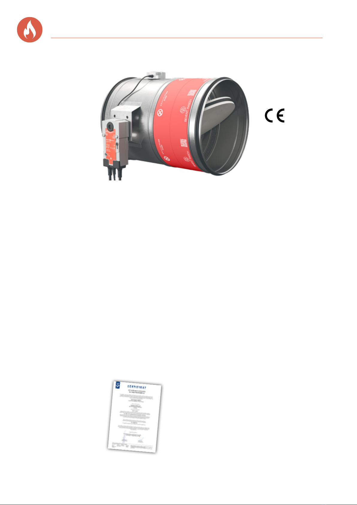
EI90 Fire damperBSKC9
Size Ø100-630 mm.
Design
BSKC9 is supplied complete with a factory mounted,
maintenance-free, 24 V electric safety actuator with ther-
mal sensor featuring built-in contacts to indicate the damp-
er position. The damper comes as standard with spiral
duct connections.
Material and surface finish
- Casing and details of galvanized steel sheet according
of environmental class C3
- EPDM duct seals
- Blade seal of PE/PP
- Blade of Calcium Silicate
Accessories
BRTO Wire mesh grille
RCKB Junction box
RCDU MRB-system, max 2 dampers
RCBK4 MRB-system, max 4 dampers
RCMU8 MRB-system, max 8 dampers
RCKD/-RD Smoke detectors
RCTU/RCTC MRB3-system, max 236 dampers
FENIX2 max 2 dampers
FENIX4 / FENIX+ max 16 dampers
Specification
Installation options for BSKC9
Size Fire class Wall of drywall
EI90 Group A,
SS-EN1363-1
Solid wall Solid floor* Duct
Ø400 - Ø630 EI90S √ √ √
Ø100 - Ø315 EI90S √ √ √ √
*125 mm lightweight
concrete
Product data for BSKC9
Size Pressure
class
Casing
tightness
SS-EN1751
Tightness
over damper
blades
SS-EN1751
2-position
actuator
On-Off
Regulating
actuator
0°-90°
Actuator
type
Ø400 - Ø630 B C 3 √ √ Belimo BFN-T
Ø100 - Ø315 B C 3** √ √ Belimo BFL-T
Pressure class B:
2500Pa
**Size
Ø100-Ø125: 2
Example:
Fire damper BSKC9 - 400 - 1 - 1
Size, nom. diameter ØD mm
Material
Galvanized sheet steel = 1
Stainless EN 1.4404 = 3
Actuator
Electric 24V with thermal sensor = 1
Electric 230V with thermal sensor = 3
Electric 24V incl. RCTU = 5
Note Factory-fitted actuator device is always included.

4BORÅS Tel +46 (0)33 - 23 67 80 STOCKHOLM Tel +46 (0)8 - 54 55 12 70
Fire damperBSKC9 EI90
Dimensions and weight
Size
Ø mm A B
Weight,
kg
100 450 – 3,0
125 450 – 3,2
160 450 – 3,5
200 450 – 4,0
250 450 30 4,5
315 450 60 5,5
400 550 60 10,5
500 550 110 13,0
630 550 180 17,0
Ød
max 55
max 200*
AB
max
65 30
Actuator - damper size
Actuator BFL-T, supplied for dampers in size Ø100-315 mm.
Actuator BFN-T, supplied for dampers in size Ø400-630 mm.
Electrical data (values in brackets refer to 230V)
* If necessary, the actuator can be rotated 90°.
Installation kit (sleeve rings) Union piece
Illustrated in
de-energised
state
Wiring
diagram
Tf1 Tf2 BAT72
Actuator
S
Ö
N
L1
M
1
2
1
2
3
4
5
6
5°
80°
Thermal
sensor
Acuator
Actuator type BFL... BFN...
Sizing, max 4 VA 6 VA
Running time.
– motor opening, max;
– spring return, max
60 s
approx. 20 s
60 s
20 s at -10 to +55°C
< 60 s at -30 to -10°C
Protection class IP 54 in all installation positions
Supply voltage 24V~ ±20%, 50/60Hz
24V= ±10% (220-240V~, 50/60Hz)
Design Imax 8,3A @ 5ms
Ambient temperature -30° to +50°C
Thermal sensor tripping
temperature
72°C
Mode contacts (Load) 1mA...3 (0,5 inductive) A, AC250V
Sound level when opening
< 43 dB (A)
Closing noise level
< 62 dB (A)
Maintenance
Maintenance-free
* Installation kit (sleeve rings)
Ø100-315 = 3 parts with 3 screws in each
Ø400-630 = 4 parts with 4 screws in each
5BORÅS Tel +46 (0)33 - 23 67 80 STOCKHOLM Tel +46 (0)8 - 54 55 12 70
1
10
100
200
Air flow (l/s)
1 10010
Total pressure drop, Pa
Sound power level
LW, dB
45
50
55
40
1
10
100
200
100 200 40010
40
45
50
55
Air flow (l/s)
Total pressure drop, Pa
Sound power level
LW, dB
1
10
100
200
10 1000100
45
50
55
60
Air flow (l/s)
Total pressure drop, Pa
Sound power level
LW, dB
1
10
100
200
10 1000100
45
50
55
60
65
Air flow (l/s)
Total pressure drop, Pa
Sound power level
LW, dB
1
10
100
200
10 100 300
40
45
50
55
Air flow (l/s)
Total pressure drop, Pa
Sound power level
LW, dB
1
10
100
200
1 10010
40
45
50
55
Air flow (l/s)
Total pressure drop, Pa
Sound power level
LW, dB
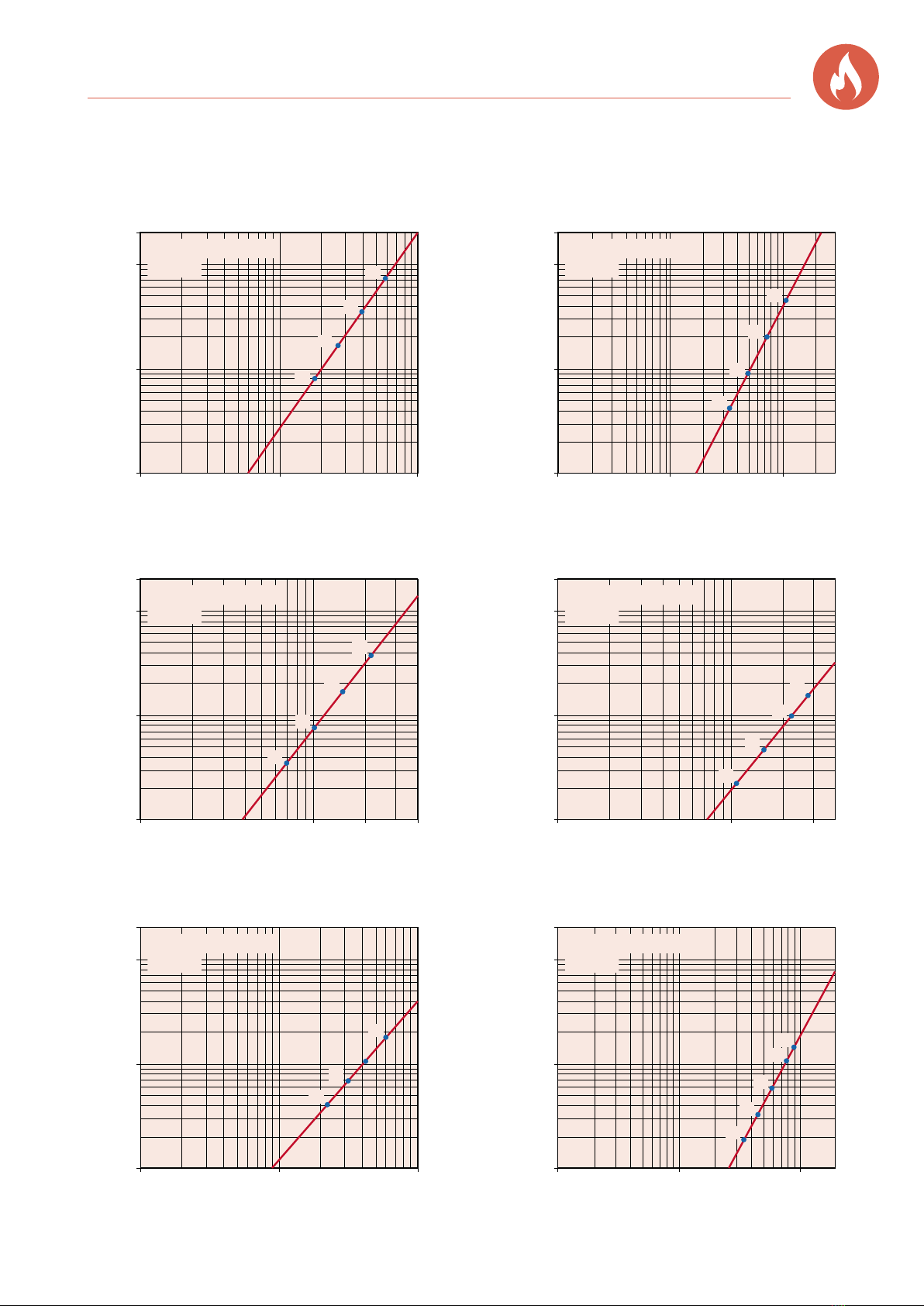
EI90 Fire damperBSKC9
Dimensioning diagram
Size - 160 Size - 200
Size - 100 Size - 125
Size - 250 Size - 315
6BORÅS Tel +46 (0)33 - 23 67 80 STOCKHOLM Tel +46 (0)8 - 54 55 12 70
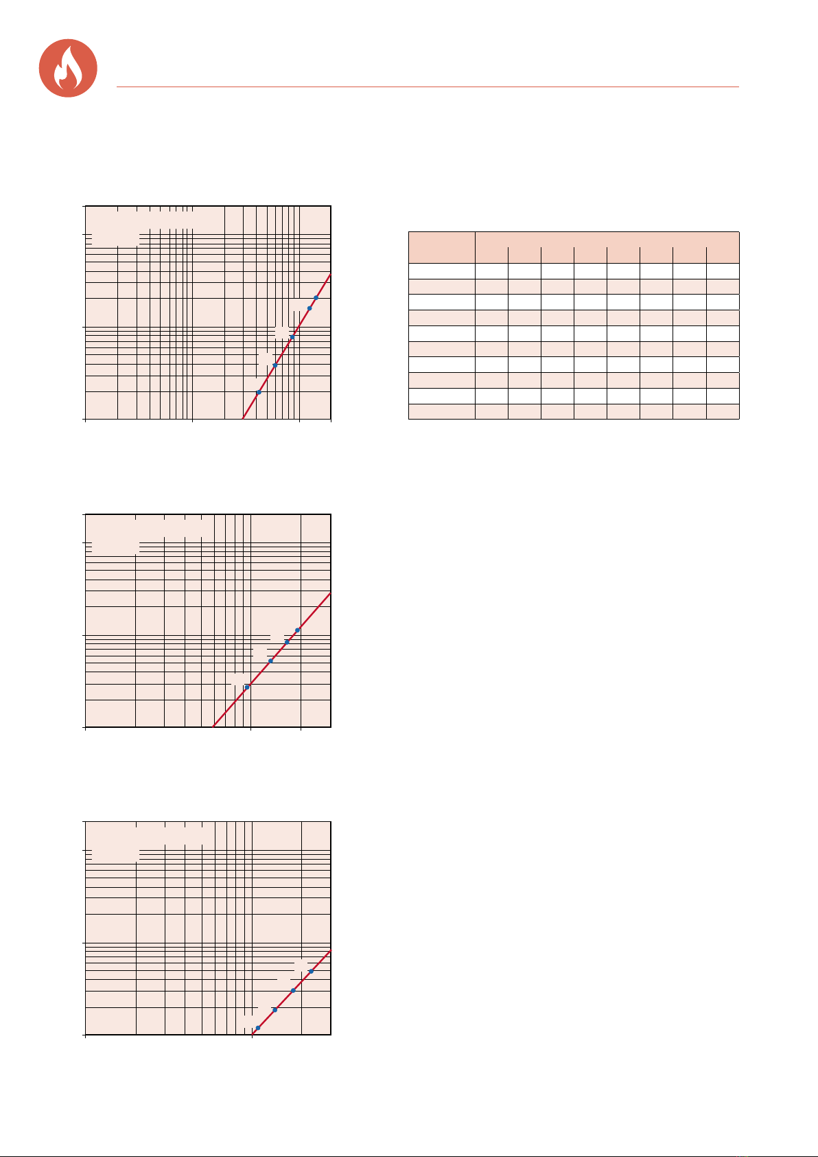
Fire damperBSKC9 EI90
Size - 500
Size - 400
Size - 630
Dimensioning diagram contd.
1
10
100
200
10 1000 2000100
45
50
55
60
65
Air flow (l/s)
Total pressure drop, Pa
Sound power level
LW, dB
1
10
100
200
100 1000 2000
50
55
60
65
Air flow (l/s)
Total pressure drop, Pa
Sound power level
LW, dB
1
10
100
200
100 1000 3000
50
55
60
65
Air flow (l/s)
Total pressure drop, Pa
Sound power level
LW, dB
Correction of sound power level, LWok, in octave band
Lwok = Lw+ Kok
Sound data
Correction, Kok
Size
Ø mm
Centre Frequency Hz
63 125 250 500 1000 2000 4000 8000
100 -4 -9 -10 -10 -10 -15 -18 -22
125 -4 -8 -8 -9 -10 -15 -21 -22
160 -4 -7 -9 -11 -14 -16 -20 -25
200 -2 -8 -11 -14 -15 -18 -23 -25
250 -2 -11 -11 -14 -14 -21 -27 -28
315 -1 -12 -14 -16 -15 -23 -29 -29
400 -2 -10 -13 -15 -15 -21 -28 -29
500 -1 -11 -14 -17 -18 -24 -31 -32
630 -1 -11 -15 -17 -17 -25 -28 -31
Tol. ± dB 1 2 5 6 6 4 3 4
7BORÅS Tel +46 (0)33 - 23 67 80 STOCKHOLM Tel +46 (0)8 - 54 55 12 70
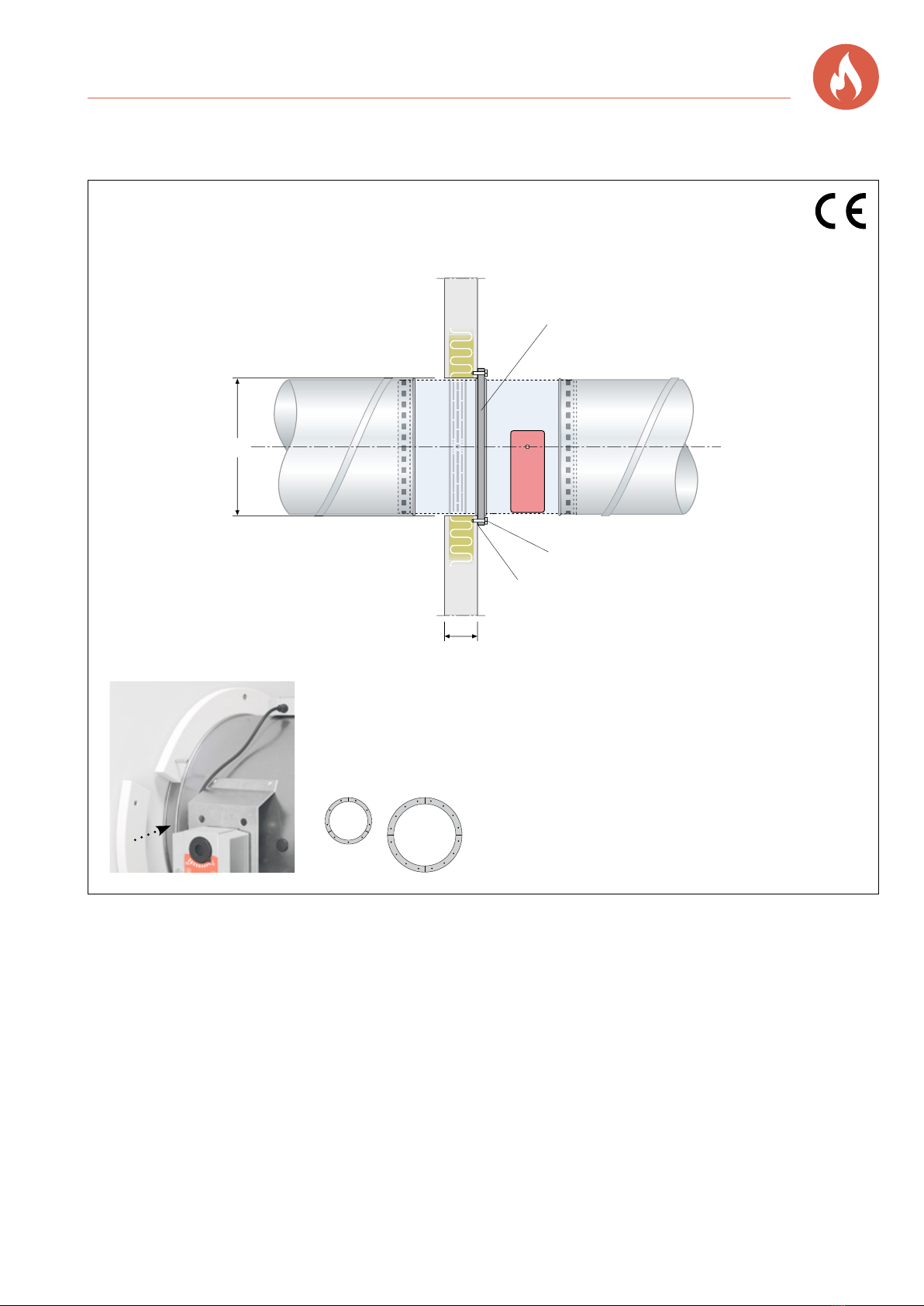
EI90 Fire damperBSKC9
1. Make a hole for size in question (d + 5mm).
2. Apply fire sealant on the wall, 20mm around the
periphery of the hole.
3. Secure the damper flat and tight with the installation kit
placed in the groove as shown in the photo. Make sure
that the shape of the damper is not impacted when
mounting.
4. Seal joints between the installation kit and damper
casing with fire sealant.
5. When installing without a duct connection, the damper
should be fitted with an incombustible grille. The
minimum distance between the open damper blade
and grille should be 50mm.
Installation in wall, fire resistance class EI90
Damper’s fire resistance class: EI90
(ve ho i <–> o) S.
EG-certificate 0402-CPR-SC0051-19
6. The duct system is fitted in accordance with current
requirements. Ensure that suspension and duct
systems do not affect the movement of the damper
blade.
• Damper for installation in walls and floors with fire re-
sistance class EI90.
• The shortest distance between dampers must be
200 mm.
• The minimum distance to the connecting structure
should be 75 mm.
• Free position on damper spindle.
d+5
Installation kit*
Screw 5x65 mm
Seal acc. to section 2 and 4.
DuctDuct
Min. thickness 95 mm
Installation instructions
* Installation kit (sleeve rings)
* Installation kit (sleeve rings)
Ø100-315 = 3 parts with 3 screws in each
Ø400-630 = 4 parts with 4 screws in each

8BORÅS Tel +46 (0)33 - 23 67 80 STOCKHOLM Tel +46 (0)8 - 54 55 12 70
Fire damperBSKC9 EI90
1. Make a hole for size in question (d + 5mm).
2. Apply fire sealant on the floor, 20mm around the pe-
riphery of the hole.
3. Secure the damper flat and tight with the installation kit
placed in the groove as shown in the photo. Make sure
that the shape of the damper is not impacted when
mounting.
4. Seal joints between the installation kit and damper
casing with fire sealant.
Installation in floor or joist systems, fire resistance class EI90.
Damper’s fire resistance class: EI90
(ve ho i <–> o) S.
EC certificate 0402-CPR-SC0051-19
5. When installing without a duct connection, the damper
should be fitted with an incombustible grille. The
minimum distance between the open damper blade
and grille should be 50mm.
6. The duct system is fitted in accordance with current
requirements. Ensure that suspension and duct
systems do not affect the movement of the damper
blade.
• Damper for mounting in floors or joist systems of at
least 125 mm lightweight concrete.
• The shortest distance between dampers must be
200mm.
• The minimum distance to the connecting structure
should be 75mm.
d+5
Installation kit*
Screw 5x65 mm
Seal acc. to section 2 and 4.
Min. thickness 125 mm
(lightweight concrete)
Duct
Duct
Installation instructions
190121.0001_ENG / Jan. 2022 teamfront.se
* Installation kit (sleeve rings)
* Installation kit (sleeve rings)
Ø100-315 = 3 parts with 3 screws in each
Ø400-630 = 4 parts with 4 screws in each
9BORÅS Tel +46 (0)33 - 23 67 80 STOCKHOLM Tel +46 (0)8 - 54 55 12 70
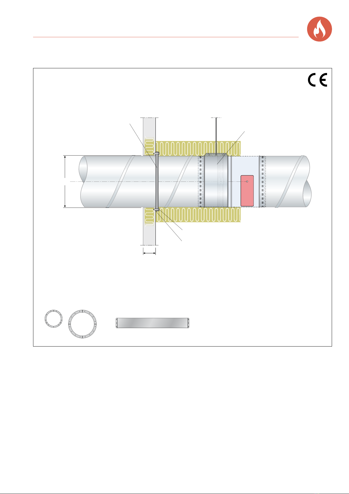
EI90 Fire damperBSKC9
1. Make a hole for size in question (d + 5mm).
2. Apply fire sealant on the wall, 20mm around the
periphery of the hole.
3. Secure the installation kit flat and tight to the wall.
4. Seal joints between the installation kit and duct with fire
sealant.
5. Fit the metal union piece over the red decal on the
cover of the damper.
6. When installing without a duct connection, the damper
should be fitted with an incombustible grille. The
minimum distance between the open damper blade
and grille should be 50mm.
Installation in horizontal ducts for size up to Ø315.
Damper’s fire resistance class: EI90
(ve ho i <–> o) S.
EC certificate 0402-CPR-SC0051-19
7. Insulate the duct, from the hole in the wall to the
actuator of the damper. Insulate the duct system EI90
according to the supplier’s instructions.
8. The duct system is fitted in accordance with current
requirements. Ensure that suspensions and duct
systems do not affect the shape of the damper or
impede the movement of the damper blade.
• Dampers for installation in duct systems,
size Ø100 - Ø315.
• The shortest distance between dampers must be
200mm.
• The minimum distance to the connecting structure
should be 75mm.
• Free position on damper spindle.
d+5
Installation kit* is mounted on the
same side as the fire damper
Suspension with
union piece
Screw 5x65 mm
Seal acc. to section 2 and 4.
Min. thickness 95 mm
DuctDuct
Installation instructions
190121.0001_ENG / Jan. 2022 teamfront.se
* Installation kit (sleeve rings and union piece)
* Installation kit (sleeve rings)
Ø100-315 = 3 parts with 3 screws in each
Ø400-630 = 4 parts with 4 screws in each
Table of contents
Other Bevent Rasch Fire And Smoke Damper manuals


Popular Fire And Smoke Damper manuals by other brands


pottorff
pottorff BD-50-SS installation instructions

Swegon
Swegon actionair DWFX-F installation guide

Fantech
Fantech FQ-FD Installation and operation manual

HVC
HVC Airtechnic NCA 100 Series Operation and maintenance manual

Lindab
Lindab FNC1 Installation booklet

mercor
mercor mcr ZIPP Operation and maintenance manual