Advanced Air 26SCD User manual

26SCD_IOM_1.4_Mar22_1
1
26SCD
FIRE & SMOKE DAMPER
AIR CONTROL
INSTALLATION, OPERATION
AND MAINTENANCE MANUAL

26SCD_IOM_1.4_Mar22_2
2
Page
Introduction and Health & Safety 3
Smoke damper – Model 26SCD
Two hour flexible wall – AFS 4
Two hour rigid wall – AFS 5
Two hour – remote from wall (duct mounted, in-line) 6
Two hour – remote from wall (duct mounted, side) 7
Wiring information
26SCD with power open / close actuator 8
26SCD multi-section with power open / close actuator 9
26SCD with modulating actuator 10
26SCD multi-section with modulating actuator 11
Spacing around damper installations 12
DW145 Fire Damper Checklist 13
Index

26SCD_IOM_1.4_Mar22_3
3
Introduction
Advanced Air (UK) Ltd have been manufacturing a comprehensive range of fire dampers and fire smoke
dampers since 1975. We have always taken pride in our products and tested to the highest standards,
originally to BS476 and now more stringent testing to CE labelling under the Construction Product Regulation
which was introduced 1st July 2013.
All our fire, fire smoke and smoke control dampers have been tested to BS EN 1366-2 and BS EN 1366-10.
This is to cover a variety of installations used on sites today. Under CE labelling all dampers must follow the
Product Standards BS EN 15650 and BS EN 12101-8 which ensures the product is consistent and supplied to
the same specification and standard as tested. Any deviation or changes from the installations in this manual
would require the dampers to be subject to a new test or approval sought from Local Building Control.
In line with product standards we are pleased to oer this installation manual covering installation, operation
and maintenance instructions together with Health and Safety information. We have also included within this
manual an example of the Fire Damper Checklist DW145 Inspection and Handover Check Sheet which is to
be completed by the installer. A separate certificate is required per damper.
The installation contained in this manual cover most installation on site. However, there are still installation
which Advanced Air (UK) Ltd have not yet tested. We are continually reviewing requirements and continuously
developing the products. As additional installation tests are carried out and classified, installations will be
added to this manual, and the Declaration of Performance (DoP) updated accordingly.
Health and Safety
Any instruction contained within this manual must be undertaken by competent trained personnel. When
completing the installation standard PPE should be used, steel toe cap boots, hard hat, gloves, protective
eyewear along with any other specific site or material instructions.
The size and weight of dampers vary, and it may require two or more persons to safely handle and move
them. Do not lift the dampers by the blades or the actuator.
For the installation of dampers at high level, the correct lifting equipment shall be used in accordance with
the Work at Height Regulations 2005 and specific site rules.
All waste materials should be collected and disposed of defined by the suppliers.

26SCD_IOM_1.4_Mar22_4
4
SMOKE CONTROL 26SCD ADJUSTABLE FRAME SYSTEM FOR TWO HOUR FLEXIBLE SUPPORTING CONSTRUCTION SUPPORT ONE SIDE
Access door
Two hour rated flexible supporting
construction to BS EN 1363-1:2020
Steel stud depth – 62-100mm
15mm thick gypsum boards
AFS bracket,
bracket slot,
and Z-piece
AFS rail
M10 drop rods
Fire batt
Nom. duct size Width Height
Opening
min.
Opening
max.
Opening
min.
Opening
max.
200mm x 200mm
and above
Nom. duct
+194mm
Nom. duct.
+350mm
Nom. duct
+100mm
Nom. duct
+350mm
Below
200mm x 200mm 394mm 550mm 300mm 550mm
Circular duct
over 175mm
Nom. duct
+219mm
Nom. dia.
+550mm
Nom. dia.
+125mm
Nom. dia.
+375mm
Circular duct
under 175mm 394mm 550mm 300mm 550mm
Preparation
1 Ensure that the damper is kept
in a clean dry environment and
that there is no damage to the
damper.
2 Remove all the packaging
before installation.
3 Work out the opening size to be
cut using the adjacent table.
Installation sequence
4 The drywall will consist of two layers of 15mm plasterboard each side of steel studwork with an optional
50mm mineral wool insulation. The opening will be a letterbox construction with overlapping layers
of plasterboard with an opening clearance around the damper casing in line with the table above.
5 Two M10 drop rods shall be fitted on the side of the drywall to which the access side of the damper
will be positioned. These should be securely installed in line with the manufacturer’s fixing instructions
in a position to match the AFS rail.
6 The drop rods should have a nut screwed on for clamping the rail from above.
7 Slide the AFS rails on each side of the damper into the brackets and insert the “Z” piece into the
bracket slot pushing it up against the underside of the rail. Insert the 8mm bolt from above into the slot
through the “Z” piece fitting the nut until tight to secure the rail.
8 The damper should be mounted centrally in the opening with the access side flush with the wall, as
detailed in the drawing. The drop rods are to slide through the slots in the rail and a nut screwed on
to take the support of the damper rail. The damper must then be levelled and when in the correct
position the nut above the rail should be tightened against the rail.
9 The galvanised mild steel ductwork connecting to the damper spigots must overlap by up to 40mm,
leaving a minimum 10mm clearance for any duct expansion in a fire situation.
10 The galvanised mild steel ductwork connections must be sealed with an approved galvanised mild
steel ductwork sealer.
11 The connecting galvanised mild steel ductwork must be independently supported within one metre of
the connections and have been installed in accordance with DW144.
12 The gap between the damper and the wall opening will need filling with two layers of 50mm thick
140kg/m fire batt cut to an interference fit and pushed in to place. All cut edges must be sealed with
a fire batt sealant to BS EN 13501-2. A fire rated intumescent mastic to BS EN 13501-2 shall be applied
to each joint.
13 An access door should be fitted on the access side of the damper for inspection and maintenance of
the damper.
14 When the damper installation has been completed checks should be made to ensure the AFS rails are
secure and there is no movement, operation of the damper should be checked.
15 Complete DW145 Fire Damper Checklist.
PRODUCT 26SCD APPLICATION FLEXIBLE SUPPORTING CONSTRUCTION W/AFS
CLASSIFICATION REPORT NO. EFR-20-002148 REV1 RC CLASSIFICATION E120 (Vew i o) S500 C 10000 AA multi • E120 (Vew i o) S500 C mod AA multi
TESTED INSTALLATION METHOD SHOWN. DIFFERING INSTALLATION METHODS TO THIS MUST BE APPROVED BY THE BUILDING CONTROL AUTHORITY (BCA) BEFORE PROCEEDING.

26SCD_IOM_1.4_Mar22_5
5
PRODUCT 26SCD APPLICATION RIGID SUPPORTING CONSTRUCTION W/AFS
CLASSIFICATION REPORT NO. EFR-20-002148 REV1 RC CLASSIFICATION E120 (Vew i o) S500 C 10000 AA multi • E120 (Vew i o) S500 C mod AA multi
TESTED INSTALLATION METHOD SHOWN. DIFFERING INSTALLATION METHODS TO THIS MUST BE APPROVED BY THE BUILDING CONTROL AUTHORITY (BCA) BEFORE PROCEEDING.
SMOKE CONTROL 26SCD ADJUSTABLE FRAME SYSTEM FOR TWO HOUR RIGID SUPPORTING CONSTRUCTION SUPPORT ONE SIDE
122mm thick, two hour rated rigid
supporting blockwork, masonry
or homogenous concrete wall
to BS EN 1363-1:2020
Access door
AFS bracket,
bracket slot,
and Z-piece
AFS rail
M10 drop rods
Fire batt
Nom. duct size Width Height
Opening
min.
Opening
max.
Opening
min.
Opening
max.
200mm x 200mm
and above
Nom. duct
+194mm
Nom. duct.
+350mm
Nom. duct
+100mm
Nom. duct
+350mm
Below
200mm x 200mm 394mm 550mm 300mm 550mm
Circular duct
over 175mm
Nom. duct
+219mm
Nom. dia.
+550mm
Nom. dia.
+125mm
Nom. dia.
+375mm
Circular duct
under 175mm 394mm 550mm 300mm 550mm
Preparation
1 Ensure that the damper is kept
in a clean dry environment and
that there is no damage to the
damper.
2 Remove all the packaging
before installation.
3 Work out the opening size to be
cut using the adjacent table.
Installation sequence
4 Two M10 drop rods shall be fitted on the side of the drywall to which the access side of the damper
will be positioned. These should be securely installed in line with the manufacturer’s fixing instructions
in a position to match the AFS rail.
5 The drop rods should have a nut screwed on for clamping the rail from above.
6 Slide the AFS rails on each side of the damper into the brackets and insert the “Z” piece into the
bracket slot pushing it up against the underside of the rail. Insert the 8mm bolt from above into the slot
through the “Z” piece fitting the nut until tight to secure the rail.
7 The damper should be mounted centrally in the opening with the access side flush with the wall, as
detailed in the drawing. The drop rods are to slide through the slots in the rail and a nut screwed on
to take the support of the damper rail. The damper must then be levelled and when in the correct
position the nut above the rail should be tightened against the rail.
8 The galvanised mild steel ductwork connecting to the damper spigots must overlap by up to 40mm,
leaving a minimum 10mm clearance for any duct expansion in a fire situation.
9 The galvanised mild steel ductwork connections must be sealed with an approved galvanised mild
steel ductwork sealer.
10 The connecting galvanised mild steel ductwork must be independently supported within one metre of
the connections and have been installed in accordance with DW144.
11 The gap between the damper and the wall opening will need filling with two layers of 50mm thick
140kg/m fire batt cut to an interference fit and pushed in to place. All cut edges must be sealed with
a fire batt sealant to BS EN 13501-2. A fire rated intumescent mastic to BS EN 13501-2 shall be applied
to each joint.
12 An access door should be fitted on the access side of the damper for inspection and maintenance of
the damper.
13 When the damper installation has been completed checks should be made to ensure the AFS rails are
secure and there is no movement, operation of the damper should be checked.
14 Complete DW145 Fire Damper Checklist.

26SCD_IOM_1.4_Mar22_6
6
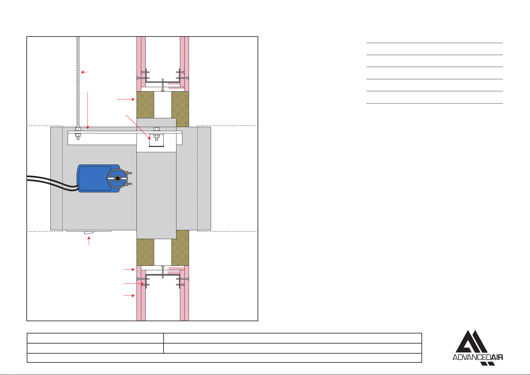
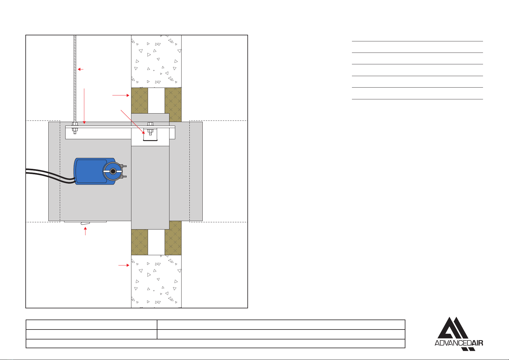
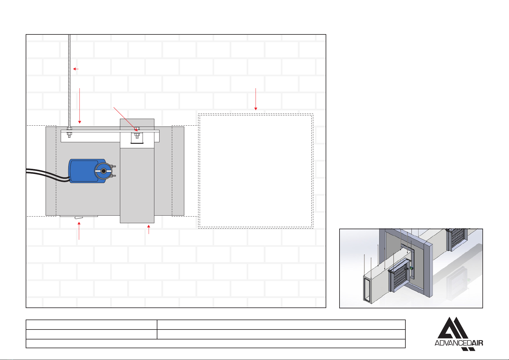
PRODUCT 26SCD W/AFS APPLICATION DUCT MOUNTED, IN-LINE, TWO HOUR REMOTE FROM WALL
CLASSIFICATION REPORT NO. EFR-20-002148 REV1 RC CLASSIFICATION E120 (Vew i o) S500 C 10000 AA multi • E120 (Vew i o) S500 C mod AA multi
TESTED INSTALLATION METHOD SHOWN. DIFFERING INSTALLATION METHODS TO THIS MUST BE APPROVED BY THE BUILDING CONTROL AUTHORITY (BCA) BEFORE PROCEEDING.
SMOKE CONTROL 26SCD TWO HOUR REMOTE FROM WALL INLINE
Preparation
1 Work out the opening size to be cut 120mm larger than the
nominal duct width/height, at a tolerance of ±5mm (for example
a 1,000 x 1,000mm duct requires a 1,120 x 1,120mm opening).
Installation sequence
2 Drill and rivet at 150mm centres, the 50x50x5mm stiening flange
to the galvanised mild steel galvanised mild steel ductwork.
3 Pass the duct through the opening, so that the flange is
centralised in the wall.
4 Drop rod anchor points, and M10 drop rods to support the
galvanised mild steel galvanised mild steel ductwork, should be
positioned within 350mm of the wall, on both sides.
5 Install Unistrut to the drop rods with M10 fixings, and adjust to
that they fully support the weight of the galvanised mild steel
galvanised mild steel ductwork, using a spreader plate. The
position of the duct should be adjusted so that the stiening
flange is centralised in every axis.
6 Fill the wall opening around the duct with 85-115kg/m2mineral
wool insulation, on both sides of the wall.
7 Fit two layers of 200mm wide, 12.5mm thick plasterboard around
the damper, overlapping the joints, to form a pattress around
the galvanised mild steel galvanised mild steel ductwork on
both sides of the wall. The pattress must be axed with drywall
screws which bite into the steel stud channel at 150mm centres,
and sealed with a bead of intumescent acrylic sealant to BS EN
13501-2, which shall be applied to back of each pattress section
before it is fitted.
8 The damper is mounted to the duct using self tapping fixings, at
150mm centres. When the duct is slid over the damper spigot,
an overlap of up to 40mm is permitted, allowing for 10mm for
duct expansion.
9 Support the damper case using a single piece of Unistrut, hung
on M10 drop rods.
10 Galvanised mild steel ductwork and sealing of the duct should
be in accordance with DW144.
11 The damper operation should be checked to ensure that it fully
opens and closes.
12 When the damper installation has been completed, checks
should be made to ensure the installation is secure, and there is
no movement.
13 Complete DW145 Fire Damper Checklist.
Fire-rated ductwork tested to BS EN 1366-8
Insulation on damper is optional.
Leave actuator uncovered for maintenance.
M10 drop rods
AFS bracket, bracket slot and Z-piece
Ductwork insulation tested to BS EN 1366-8
This is an example illustration –
installations through the wall may
vary and should be carried out in
accordance with BS EN 1366-8.
Wall construction must be in
accordance with the ductwork
manufacturer’s specifications
Mineral wool insulation 85-115 kg/m
15mm thick gypsum boards
2x 12.5mm thick gypsum boards, forming pattress
Access door
50x50x5mm
stiening angle
Group A 122mm (or thicker) two hour rated flexible
supporting construction to BS EN 1363-1:2020
Steel stud

26SCD_IOM_1.4_Mar22_7
7
SMOKE CONTROL 26SCD TWO HOUR REMOTE FROM WALL SIDE MOUNTED
Installation sequence
1 Install drop rod anchor points, and M10 drop rods to support
the damper, using the AFS (Adjustable frame system). M10
drop rod lengths should be a maximum of 1,000mm in length.
Where longer lengths are required, the bottom 1,000mm of M10
drop rod should be joined to an M16 drop rod above for the
remainder of the length, using M16/M10 transition pieces.
2 Slide the AFS rails on each side of the damper into the brackets
and insert the “Z” piece into the bracket slot pushing it up against
the underside of the rail. Insert the 8mm bolt from above into the
slot through the “Z” piece fitting the nut until tight to secure the rail.
3 The drop rods are to slide through the slots in the rail and a nut
screwed on to take the support of the damper rail. The damper
must then be levelled, and when in the correct position the nut
above the rail should be tightened against the rail.
4 The damper is mounted to the duct using self tapping fixings,
at 150mm centres. When the damper is slid into the duct, an
overlap of up to 40mm is permitted, allowing for 10mm for duct
expansion.
5 The connecting galvanised mild steel ductwork must be
independently supported within one metre of the connections
and have been installed in accordance with DW144.
6 An access door should be fitted on the access side of the
damper for inspection and maintenance of the damper.
7 The damper operation should be checked to ensure that it fully
opens and closes.
8 When the damper installation has been completed checks
should be made to ensure the AFS rails are secure and there is
no movement, operation of the damper should be checked.
9 Complete DW145 Fire Damper Checklist.
Access door
AFS bracket,
bracket slot,
and Z-piece
AFS rail Ductwork to BS EN 1366-8
M10 drop rods
Insulation on damper is optional.
Leave actuator uncovered for maintenance.
PRODUCT 26SCD W/AFS APPLICATION DUCT MOUNTED, SIDE MOUNTED, TWO HOUR REMOTE FROM WALL
CLASSIFICATION REPORT NO. EFR-20-002148 REV1 RC CLASSIFICATION E120 (Vedw i o) S500 C 10000 AA multi • E120 (Vedw i o) S500 C mod AA multi
TESTED INSTALLATION METHOD SHOWN. DIFFERING INSTALLATION METHODS TO THIS MUST BE APPROVED BY THE BUILDING CONTROL AUTHORITY (BCA) BEFORE PROCEEDING.

26SCD_IOM_1.4_Mar22_8
8
12345678
G:\PRODUCTS\DMP - 2500 Series\02 Engineering\Drawings\D2500 - ES - Electrical\26SCD\D26SCD ES001 General wiring\D26SCD ES001 Rev D - General wiring.dwg
WIRING INSTRUCTIONS 26SCD WITH POWER OPEN / CLOSE ACTUATOR
Wiring detail for dampers fitted with powered open/close actuators Johnson M9116-ADC-1N4 (230V AC) or M9116-AGC-1N4 (24V AC/DC).

26SCD_IOM_1.4_Mar22_9
9
12345678
G:\PRODUCTS\DMP - 2500 Series\02 Engineering\Drawings\D2500 - ES - Electrical\26SCD\D26SCD ES001 General wiring\D26SCD ES001 Rev D - General wiring.dwg
WIRING INSTRUCTIONS 26SCD MULTISECTION WITH POWER OPEN / CLOSE ACTUATOR
Wiring detail for dampers fitted with powered open/close actuators Johnson M9116-ADC-1N4 (230V AC) or M9116-AGC-1N4 (24V AC/DC).

26SCD_IOM_1.4_Mar22_10
10
12345678
G:\PRODUCTS\DMP - 2500 Series\02 Engineering\Drawings\D2500 - ES - Electrical\26SCD\D26SCD ES001 General wiring\D26SCD ES001 Rev D - General wiring.dwg
Wiring detail for dampers fitted with modulating actuators Johnson M9116-GGC-1N4 (24V AC/DC with 0-10VDC control).
WIRING INSTRUCTIONS 26SCD WITH MODULATING ACTUATOR

26SCD_IOM_1.4_Mar22_11
11
12345678
G:\PRODUCTS\DMP - 2500 Series\02 Engineering\Drawings\D2500 - ES - Electrical\26SCD\D26SCD ES001 General wiring\D26SCD ES001 Rev D - General wiring.dwg
Wiring detail for dampers fitted with modulating actuators Johnson M9116-GGC-1N4 (24V AC/DC with 0-10VDC control). A maximum of five actuators can be connected this way.
WIRING INSTRUCTIONS 26SCD MULTISECTION WITH MODULATING ACTUATOR

26SCD_IOM_1.4_Mar22_12
12
SPACING AROUND DAMPER INSTALLATIONS
Supporting construction
BS EN 1366-2:2015 section 7.3 states “the distance between the fire dampers shall not be less the 200mm.”
Multiple ducts in one large opening is not currently included in a harmonised standard, but this is being
investigated by standards committees.
Surrounding construction
BS EN 1366-2:2015 section 13.6 states “minimum separation of 75mm between fire damper and a construction
element (wall /floor).”
Wall opening
200mm
minimum
Wall opening
Damper
casing
Damper
casing
75mm
minimum
75mm
minimum
Wall opening
Damper casing

26SCD_IOM_1.4_Mar22_13
13
Fire Damper Certificate
CE-020
CE Certification
Rev 01
June 2019
S Manning
DW 145 Inspection & Handover Check Sheet to be completed by the installer with a separate
certificate for each damper.
No.
Question
Guidelines
Tick
1 Are the dampers the correct type?
Fire Damper Model 0160, 0400MAN
Fire Damper Model 2550, 2530, 26SCD
and 0400FME
2 Are the dampers correctly identified?
Identification label clearly shows the
damper individual reference number
3 Are the dampers located correctly?
The damper position matches the
position as detailed on the
manufactures installation instructions
4
Have supports for both the damper and
the adjacent ductwork been installed in
accordance with the approved method?
5
Are the dampers fitted in the correct
orientations?
The dampers are installed the correct
way up relative to airflow and access
6 Is access, through the ductwork to the
damper unobstructed?
There is unobstructed space to allow
safe access to damper, also through
ceiling void and adjacent services
7
Confirm the space around the damper has
not been used for the passage of other
services
The presence of other services will
invalidate the installation method
8
Using the access opening provided,
confirm that the damper has been left in
the open position
9
Release the damper catch to simulate the
thermal release mechanism (damper drop
test)
Ensure the blade operation is free from
interference
10 Check damper blades for damage
With the damper in the closed position
inspect for damage
11 Re-set damper and replace access panel
After resetting check that if supplied
the visual position indicator is correct
12 Is the fire barrier and penetration seal
complete?
Confirm at handover if installation is
complete and if no then other trades
will be required to finish
13 Handover damper installation for
commissioning
Obtain relevant acceptance of the
damper installation from the
nominated person responsible
Project
Installer Name
Damper ID No:
Company
Location
Date
Type
I hereby confirm the damper detailed has been installed and
tested according to the manufactures recommendations
Model No:
Signature
Fire Damper Checklist
Table of contents
Other Advanced Air Fire And Smoke Damper manuals
Popular Fire And Smoke Damper manuals by other brands

Mandik
Mandik SEDM Technical documentation

mercor
mercor mcr S-THERM C Operation and maintenance manual

Komfovent
Komfovent UVA30-D-t installation instructions

Mandik
Mandik FDMC installation instructions

HVC
HVC NCA Series installation guide

pottorff
pottorff CD-81 Installation, operation and maintenance manual