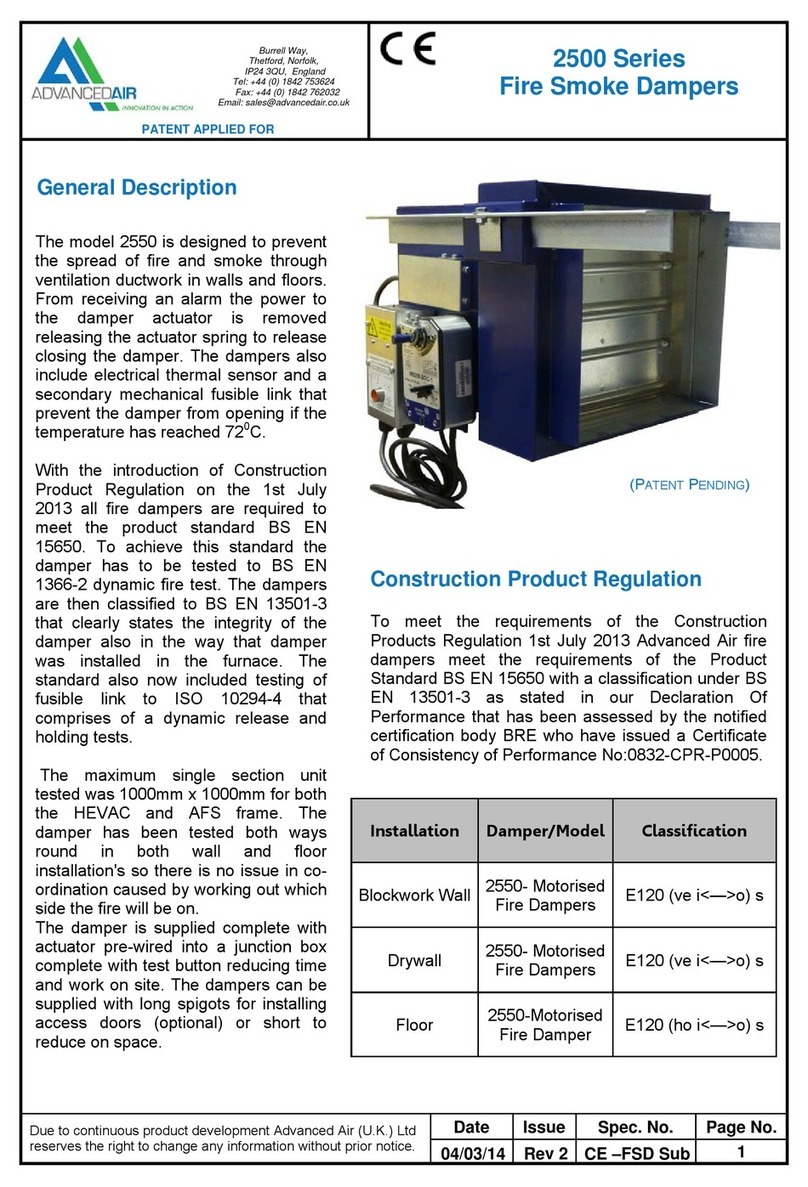
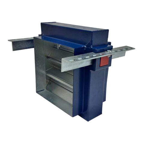
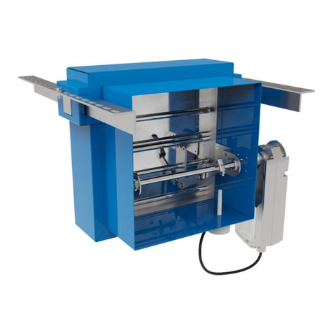
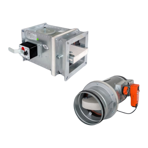
Advanced Air 2530 CE Series User manual

Advanced Air UK Ltd
Burrell Way
Thetford
Norfolk IP24 3QU
Tel: 01842 765657
mail: Projects@advan
c
edair.co.uk
2530 CE Series
Smoke Fire Damper
Due to continuous product development Advanced
(U.K.) Ltd reserves the right to change any
information without prior notice
Date Issue Sheet Spec umber
April 2018 C 1 of 34 TS2530CE-01
G:\PRODUCTS\DMP - 2500 Series\05 Product Data\2530\Tech Sub\2530CE\TS2530CE-01 Technical Sub Rev C.docx
General Description
The model 2530 is designed to prevent the spread of fire and smoke through ventilation ductwork in walls and
floors. When the power to the damper actuator is removed, the actuator spring is released, which closes the
damper.
Advanced Air 2530 dampers are tested to BS E 1366-2, BS E 15650 and BS ISO 10294-4. They are then classified
to BS E 13501-3 so that the performance can be certified.
The damper is supplied complete with an actuator pre-wired with flying leads for electrical connection. A test
button is also included for checking the actuator operation. The dampers are supplied with long spigots for
installing access doors (optional).

Advanced Air UK Ltd
Burrell Way
Thetford
Norfolk IP24 3QU
Tel: 01842 765657
mail: Projects@advan
c
edair.co.uk
2530 CE Series
Smoke Fire Damper
Due to continuous product development Advanced
(U.K.) Ltd reserves the right to change any
information without prior notice
Date Issue Sheet Spec umber
April 2018 C 2 of 34 TS2530CE-01
G:\PRODUCTS\DMP - 2500 Series\05 Product Data\2530\Tech Sub\2530CE\TS2530CE-01 Technical Sub Rev C.docx
Product Details
Blades Opposed blades, double skinned
Width 136mm standard
Centres 125mm
Material 1.0mm Gal anised Mild Steel – Standard
1.0mm Grade 430 Stainless Steel - Optional
Frame Frame depth 113mm – with 250mm spigot and 50mm spigot as standard units
with a duct size under 200mm, circular and flat o al spigotted units will be
supplied with additional step down spigots
Material 1.2mm Gal anised – Standard
1.2mm Grade 430 Stainless Steel – Optional
Corners Welded mitre corners finished with aluminium aerosol spray.
Seals Options Semi Sealed Fitted with stainless steel side jamb seals.
(Due to the unique design of the damper blades, blade seals are not
required)
Linkage External, Zinc electroplated mild steel enclosed with the frame, out of airstream, fixed for
90 degree operation – Standard
Bearings 12.7mm diam. Oil Filled Sintered Bronze suitable for use up to 200°C – Standard
12.7mm diam. Stainless Steel suitable for use up to 650°C - Optional
Axles 12.7mm diam. Zinc Electroplated Mild Steel bolted directly through blade
Jackshaft 12.7mm diameter zinc electroplated mild steel
Side Jamb Cambered 430 Stainless Steel
Top & Bottom Jambs Profiled grade 430 stainless steel
En ironment These units are not suitable for installation with a corrosi e or hostile en ironment or an
area of high humidity.
Casing (Ducting) Class C DW144
Leakage
Electric Control The 2530CE fire/smoke damper is supplied complete with factory fitted actuator(s). Each
actuator is complete with olt-free open and closed indication micro-switches as standard.

Advanced Air UK Ltd
Burrell Way
Thetford
Norfolk IP24 3QU
Tel: 01842 765657
mail: Projects@advan
c
edair.co.uk
2530 CE Series
Smoke Fire Damper
Due to continuous product development Advanced
(U.K.) Ltd reserves the right to change any
information without prior notice
Date Issue Sheet Spec umber
April 2018 C 3 of 34 TS2530CE-01
G:\PRODUCTS\DMP - 2500 Series\05 Product Data\2530\Tech Sub\2530CE\TS2530CE-01 Technical Sub Rev C.docx
Minimum and maximum permissible duct sizes
As standard, all dampers shall be shipped as single section up a nominal duct size of 1000mm x1000mm.Dampers
larger than this will be shipped as a multi-section damper fixed together at Ad anced Air and shipped as one piece.
Dampers larger than 2050mm wide or 2050mm high will be split and shipped as separate pieces, each piece being
no larger than a duct size of 2050mm x 2050mm. Below are the minimum and maximum sizes possible (A ailable
in 1mm increments).
Duct Size Rectangular: Minimum 100mm wide x 100mm high (Case size 250mm x 250mm)
(single-section) Maximum Single Section 1000mm wide x 1000mm high
Circular: Minimum 100mm diameter (case size 250mm x 250mm)
Maximum 950mm diameter
Flat O al: Minimum 100mm wide x 100mm high (Case size 250mm x 250mm)
Maximum 950mm on longest dimension.
Duct Size Rectangular: Maximum multi-section 2050mm wide x 2050mm high
(multi-section Circular: Maximum 1500mm Diameter.
shipped on one piece) Flat O al: Maximum 1500mm on longest dimension.
Duct Size Rectangular: Maximum multi-section - None stated *See below
(multi-section Circular: Not a ailable
shipped in separate Flat O al: Not a ailable
pieces)
* Further structural support may be required, please consult a Structural Engineer for advice

Advanced Air UK Ltd
Burrell Way
Thetford
Norfolk IP24 3QU
Tel: 01842 765657
mail: Projects@advan
c
edair.co.uk
2530 CE Series
Smoke Fire Damper
Due to continuous product development Advanced
(U.K.) Ltd reserves the right to change any
information without prior notice
Date Issue Sheet Spec umber
April 2018 C 4 of 34 TS2530CE-01
G:\PRODUCTS\DMP - 2500 Series\05 Product Data\2530\Tech Sub\2530CE\TS2530CE-01 Technical Sub Rev C.docx
Product codin table
Variable
Code
Description
Mounting Type Options AFFL Adjustable frame system for floor mounting
AFWA Adjustable frame system for wall mounting
HVF HEVAC frame
Dri e Position DBS Dri e Both Side
DBTM Dri e at the bottom (Blades will be ertical orientation)
DTOP Dri e at the top (Blades will be ertical orientation)
COMT External side dri e outer sections (Horizontal blades), Dri e top
centre sections (Vertical blades)
COMB External side dri e outer sections (Horizontal blades), Dri e bottom
centre sections (Vertical blades).
LH Left hand dri e (Blades will be horizontal orientation)
RH
Ri ht hand drive (Blades will be horizontal orientation)
Blade orientation when
installed
H
Horizontal orientation blades
V Vertical orientation blades (manufactured as RH units and rotated)
COM Both orientation of blades (typically on multi-section units)
Duct Connection C Circular Spigot Connection
O Flat O al Spigot Connection
R Square or Rectangular Spigot Connection
Frame material
GLV
Galvanised mild Steel
430C Grade 430 stainless steel
Blade Material
GLV
Galvanised mild Steel
430B Grade 430 stainless steel
Thermal closure de ice
TFA
74°C Thermal sensor on actuator flyin lead
Bearings
OIL
Oilite Bearin s suitable for use up to
200°C
SS Stainless Steel suitable for use up to 650°C
Operation options
FME
Factory Mounted Electrical Actuator
Actuator Mounting AMH Horizontal (Only with horizontal blades)
AMVU Vertical up (Only with horizontal blades)
AMVD
Vertical down
(Only with horizontal blades)
Actuator Operation SC Sprin Closed
Actuator S4TS 24VAC/DC spring return
S3TS 230VAC spring return
Additional cables DLF2 Decoder plug mounted on end of 2 metre fly lead (supplied loose)
DLF5 Decoder plug mounted on end of 5 metre fly lead (supplied loose)
Access doors ADF Access door fitted per unit
ADFS Access door fitted per section
Example
Qty- 2530CE- Duct Size (W X H)-AFWA-RH-H-R-GLV-GLV-TFA-OIL-FME-AMH-SC-S4TS- DLF5
Bold reen items show the option that is automatically selected as standard
All sizes to be ordered as duct size. All sizes to be gi en as width by height or diameter
Restrictions apply to certain model/ ariable selections – please see product details.

Advanced Air UK Ltd
Burrell Way
Thetford
Norfolk IP24 3QU
Tel: 01842 765657
mail: Projects@advan
c
edair.co.uk
2530 CE Series
Smoke Fire Damper
Due to continuous product development Advanced
(U.K.) Ltd reserves the right to change any
information without prior notice
Date Issue Sheet Spec umber
April 2018 C 5 of 34 TS2530CE-01
G:\PRODUCTS\DMP - 2500 Series\05 Product Data\2530\Tech Sub\2530CE\TS2530CE-01 Technical Sub Rev C.docx
Further information on product codin options
Sizes and sections
Maximum and minimum sizes
The maximum and minimum sizes possible are detailed under
‘Product details’ (See previous pages). These refer to the maximum
size for a single section; one single damper.
The maximum possible size of a single section is constrained by the
sizes of component parts that can be manufactured in our factory
as well as the sizes that have been tested in order to achieve CE
labelling.
Single and Multi-section
Wherever possible Advanced Air supply dampers in single sections as
this keeps the cost of the product to a minimum. However when the
size falls outside of the requirements for a single section damper we
will supply a multi-section damper instead.
A multi-section damper is one that is made up of 2 or more single
dampers. Wherever possible these single dampers are joined in the
Advanced Air factory to minimise the work required on site. However
where dampers are supplied in separate sections they will be
required to be joined on site. Multi-section 2500 Series dampers of
up to 2 sections wide by 2 sections high are supplied joined by steel
channel inside and wrapped with their own spigot case, making the 4
section damper appear as a single unit. On dampers larger than 4
sections wide by 2 sections high they are produced as separate spigotted dampers and joined in our factory using
joining strips. Where dampers are too large to be shipped as one piece Advanced Air will supply the joining stips
for use on site.
Important note on structural support. Under the requirements of BS
E 15882-2:2015 (Point 5.2.2.2), dampers that are more than 2
sections high must be structurally supported to a fire safe design
provided by competent structural engineers.
Every damper section must have one side exposed, there must be a
clear side to mount the actuator. Therefore dampers more than 2
sections wide cannot be any more than 2 sections high; dampers
more than 2 sections high cannot be more than 2 sections wide.

Advanced Air UK Ltd
Burrell Way
Thetford
Norfolk IP24 3QU
Tel: 01842 765657
mail: Projects@advan
c
edair.co.uk
2530 CE Series
Smoke Fire Damper
Due to continuous product development Advanced
(U.K.) Ltd reserves the right to change any
information without prior notice
Date Issue Sheet Spec umber
April 2018 C 6 of 34 TS2530CE-01
G:\PRODUCTS\DMP - 2500 Series\05 Product Data\2530\Tech Sub\2530CE\TS2530CE-01 Technical Sub Rev C.docx
Mounting type options
HVF - HEVAC Installation Frame
The installation frame is factory fitted to its respecti e fire damper and the assembly is deli ered
to site as one unit. It remo es the need for slee e and angle fitting and allows expansion of the
damper in a fire condition within the frame, so that the integrity of the fire wall or floor is not
affected.
When the damper is
installed these fold out
tabs are encased in the
concrete to hold the
damper firmly in place.
Flange with fixing tabs
ensures maximum
captive strength when
fitted.
Corner mitres allow
for frame expansion.
Damper is located
centrally using folded
corner spacers.
Corner joints fitted with aluminium
rivets ensures unimpeded expansion of
frame.

Advanced Air UK Ltd
Burrell Way
Thetford
Norfolk IP24 3QU
Tel: 01842 765657
mail: Projects@advan
c
edair.co.uk
2530 CE Series
Smoke Fire Damper
Due to continuous product development Advanced
(U.K.) Ltd reserves the right to change any
information without prior notice
Date Issue Sheet Spec umber
April 2018 C 7 of 34 TS2530CE-01
G:\PRODUCTS\DMP - 2500 Series\05 Product Data\2530\Tech Sub\2530CE\TS2530CE-01 Technical Sub Rev C.docx
AFFL and AFWA - AFS Adjustable Frame System)
The adjustable frame system consists of brackets mounted to the sides of the damper, these can be
used to support the damper’s weight on two angled bars with slotted holes for mounting. The solution
offers a ersatile way to install a damper that can be easily re-positioned if necessary, whilst also
allowing the installation of the damper itself to be carried by the ductwork contractor before the building
work is finished. In fact an AFS damper can even be installed before the wall is erected!
The AFS is a low-cost and yet highly ersatile solution designed to make damper installation problems
on site a thing of the past.
Because of the clever design of the AFS…
• The damper can be hung before the actual installation
has taken place.
• The damper can be easily repositioned by sliding it up
and down the rail, or adjusting the drop rod fixings.
• The installation is simple and clean, using Firebatt and
sealant.
Support brackets are
fitted to the sides of
the damper.
Angled bars are then
slid into the brackets
and can be used to
hang the damper in its
installed position.

Advanced Air UK Ltd
Burrell Way
Thetford
Norfolk IP24 3QU
Tel: 01842 765657
mail: Projects@advan
c
edair.co.uk
2530 CE Series
Smoke Fire Damper
Due to continuous product development Advanced
(U.K.) Ltd reserves the right to change any
information without prior notice
Date Issue Sheet Spec umber
April 2018 C 8 of 34 TS2530CE-01
G:\PRODUCTS\DMP - 2500 Series\05 Product Data\2530\Tech Sub\2530CE\TS2530CE-01 Technical Sub Rev C.docx
Actuator options and Drive position
Drive location LH and RH
Drive location DBS – Drive both sides
This applies to 2 section wide dampers only. Drive both sides is where each individual section of the damper has
its own driveshaft either side of the damper assembly.
Drive location DBTM – Drive bottom
This signifies that the drive is at the bottom. The actuator shall be fitted at the bottom of the damper and the
blades shall be vertically orientated. Spacers will be fitted to the linkage at the top of the damper to prevent
blades dragging on the bottom seals.
Drive location DTOP – Drive top
This signifies that the drive is at the top. The actuator shall be fitted at the top of the damper and the blades shall
be vertically orientated. Spacers will be fitted to the linkage at the top of the damper to prevent blades dragging
on the bottom seals.
Drive location COMT – Drive External outer and top centre
On a multi-section damper only; this signifies that the outer dampers will have actuators on the sides and the
centre dampers will have actuators on the top. The outer dampers will therefore have horizontal blades and the
centre dampers will have vertical blades. On vertical blade dampers spacers will be fitted to the linkage at the top
of the damper to prevent blades dragging on the bottom seals.
Right handed damper RH) - Default
The right handed damper has the
actuator shaft on the right hand side
as you view the damper looking into
the access side (long spigot).
Left handed damper LH)
The left handed damper has the
actuator shaft on the left hand side
as you view the damper looking
into the access side (long spigot).

Advanced Air UK Ltd
Burrell Way
Thetford
Norfolk IP24 3QU
Tel: 01842 765657
mail: Projects@advan
c
edair.co.uk
2530 CE Series
Smoke Fire Damper
Due to continuous product development Advanced
(U.K.) Ltd reserves the right to change any
information without prior notice
Date Issue Sheet Spec umber
April 2018 C 9 of 34 TS2530CE-01
G:\PRODUCTS\DMP - 2500 Series\05 Product Data\2530\Tech Sub\2530CE\TS2530CE-01 Technical Sub Rev C.docx
Drive location COMB – Drive External outer and bottom centre
On a multi-section damper only; this signifies that the outer dampers will have actuators on the sides and the
centre dampers will have actuators on the bottom. The outer dampers will therefore have horizontal blades and
the centre dampers will have vertical blades. On vertical blade dampers spacers will be fitted to the linkage at the
top of the damper to prevent blades dragging on the bottom seals.
Blade orientation V, H and COM Vertical, Horizontal and Combination)
The blade orientation can be changed to suit customer requirements. Horizontal blades are used with a side
mounted actuator, where as vertical blades allow the actuator to be mounted at the top or bottom.
Where vertical blades are fitted, the linkage at the top of the damper is fitted with spacers to prevent the blades
dragging on the bottom seals.
On multi-section dampers there can be a combination of horizontal and vertical blade dampers. In this instance
the product code COM is used.
Horizontal blades Vertical blades

Advanced Air UK Ltd
Burrell Way
Thetford
Norfolk IP24 3QU
Tel: 01842 765657
mail: Projects@advan
c
edair.co.uk
2530 CE Series
Smoke Fire Damper
Due to continuous product development Advanced
(U.K.) Ltd reserves the right to change any
information without prior notice
Date Issue Sheet Spec umber
April 2018 C 10 of 34 TS2530CE-01
G:\PRODUCTS\DMP - 2500 Series\05 Product Data\2530\Tech Sub\2530CE\TS2530CE-01 Technical Sub Rev C.docx
Actuator mounting
The actuator can be mounted horizontally along the damper or vertically. This should be specified at order
placement. The damper can also be mounted underneath in a horizontal, left or right handed orientation.
Examples are shown below.
For dampers with Horizontal orientated blades (These would be coded H)
Horizontal Left (LH, AMH) Horizontal Right (RH, AMH)
Vertical Left (LH, AMVD) Vertical Right (RH, AMVD)
Note: When the nominal duct size is 28 mm or less, wall mounted dampers in the Horizontal actuator
orientation shown above will require an extended actuator bracket in order to prevent the actuator fouling
on the AFS bracket and rail. Floor mount dampers will always use the standard bracket.
In all cases the actuator will protrude over the spigot edge by 5 mm. The actuator will be spaced away
from the spigot to allow fitment of duct.
Note: The actuator will be level with the edge of the spigot on dampers of 42 mm nominal duct height. All
dampers smaller 42 mm than this will have actuator protrusion over the edge of the damper spigot.

Advanced Air UK Ltd
Burrell Way
Thetford
Norfolk IP24 3QU
Tel: 01842 765657
mail: Projects@advan
c
edair.co.uk
2530 CE Series
Smoke Fire Damper
Due to continuous product development Advanced
(U.K.) Ltd reserves the right to change any
information without prior notice
Date Issue Sheet Spec umber
April 2018 C 11 of 34 TS2530CE-01
G:\PRODUCTS\DMP - 2500 Series\05 Product Data\2530\Tech Sub\2530CE\TS2530CE-01 Technical Sub Rev C.docx
Vertical Up Left (LH, AMVU) Vertical Up Left (RH, AMVU)
Important note: Floor dampers under 450mm nominal duct height cannot be supplied with AMVD or AMVU
motor con igurations as the actuator will clash with the AFS rame bars.
Dampers with Vertical blades (These would be coded V)
The vertical blade damper is the same construction as a horizontal bladed damper, other than the addition of
spacers, and the orientation of mounting accessories. On a vertical bladed damper, spacers will be fitted to the
linkage at the top of the damper. The orientation of mounting accessories (e.g. AFS frame) will be re-positioned to
suit installation on vertical bladed dampers. Therefore the standard codes (LH, RH, AMH, AMVD, AMVU) are used
to produce a vertically bladed damper with the actuator in the correct orientation.
Dampers with the actuator on the bottom will be coded DBTM, examples are shown below:
Underneath Horizontal (LH, AMH) Underneath Left (LH, AMVD) Underneath Right (LH, AMVU)
The actuator will protrude
over the spigot by 5 mm in all
cases.
Note: Dampers in these two vertical up orientations shown above will require an extended actuator
bracket when the Nominal duct height is under 58 mm. In these cases there will also be protrusion of the
actuator over the side of the damper spigot.
The actuator will protrude
over the spigot on all dampers
42 mm nominal duct height
and smaller.
The actuator will protrude
over the spigot on all dampers
58 mm nominal duct height
and smaller.

Advanced Air UK Ltd
Burrell Way
Thetford
Norfolk IP24 3QU
Tel: 01842 765657
mail: Projects@advan
c
edair.co.uk
2530 CE Series
Smoke Fire Damper
Due to continuous product development Advanced
(U.K.) Ltd reserves the right to change any
information without prior notice
Date Issue Sheet Spec umber
April 2018 C 12 of 34 TS2530CE-01
G:\PRODUCTS\DMP - 2500 Series\05 Product Data\2530\Tech Sub\2530CE\TS2530CE-01 Technical Sub Rev C.docx
Dampers with the actuator at the top will be coded DTOP, examples are shown below:
Top Horizontal (RH, AMH) Top Left (RH, AMVD) Top Right (RH, AMVU)
Multi-section dampers with three sections will have a centre section with vertical blades. The centre
section can have the actuator at the top and at bottom. These configurations would be coded as COMT
(External drive outer sections/horizontal blades and central sections drive on top/vertical blades) or
COMB (External drive outer sections/horizontal blades and central sections drive on top/vertical
blades). Where dampers are 2 sections high and coded COMT or COMB, there will be actuators at the
top and bottom on centre sections.
The actuator will protrude
over the spigot by 5 mm in all
cases.
The actuator will protrude
over the spigot on all dampers
42 mm nominal duct height
and smaller.
The actuator will protrude
over the spigot on all dampers
58 mm nominal duct height
and smaller.

Advanced Air UK Ltd
Burrell Way
Thetford
Norfolk IP24 3QU
Tel: 01842 765657
mail: Projects@advan
c
edair.co.uk
2530 CE Series
Smoke Fire Damper
Due to continuous product development Advanced
(U.K.) Ltd reserves the right to change any
information without prior notice
Date Issue Sheet Spec umber
April 2018 C 13 of 34 TS2530CE-01
G:\PRODUCTS\DMP - 2500 Series\05 Product Data\2530\Tech Sub\2530CE\TS2530CE-01 Technical Sub Rev C.docx
Approved Actuators
Because the 2530 is a CE certified product, only approved actuators which have been subjected to the correct
testing can be used on the product. The following is a list of actuators which are approved for use on the damper.
• AA230TS18 (230V AC 18 m Spring return, 2 aux switches, Thermal monitoring unit) code S3TS
• AA24TS18 (24V AC/DC 18 m Spring return, 2 aux switches, Thermal monitoring unit) code S4TS
TFA – 72°C Thermal fuse
The 2530 series is fitted with 3 thermal fuses which work
together to provide a total fire safety solution. There are 2
thermal fuses for monitoring the duct temperature, and one for
the ambient temperature. If the temperature of any of these
fuses exceeds the rated level, the power supply will be
irreversibly cut. As a result the return spring will drive the
actuator to the failsafe position. There is a test button on the sensor head for testing the
operation.
SC – Spring closed Actuator operation
The operation of a CE marked damper must be configured as Spring Closed (SC).
DLF2 and DLF5 – Decoder leads
A decoder lead is a length of cable with a special plug on the end of it for
connecting into a System 42 damper decoder. The lead will be pre-wired by
Advanced Air into the plug but it will not be wired to anything else at the
other end. A contractor on site shall wire the decoder lead to the damper(s)
on site using the wiring diagrams provided by Advanced Air. o junction boxes or additional cable are provided by
Advanced Air.

Advanced Air UK Ltd
Burrell Way
Thetford
Norfolk IP24 3QU
Tel: 01842 765657
mail: Projects@advan
c
edair.co.uk
2530 CE Series
Smoke Fire Damper
Due to continuous product development Advanced
(U.K.) Ltd reserves the right to change any
information without prior notice
Date Issue Sheet Spec umber
April 2018 C 14 of 34 TS2530CE-01
G:\PRODUCTS\DMP - 2500 Series\05 Product Data\2530\Tech Sub\2530CE\TS2530CE-01 Technical Sub Rev C.docx
Duct connection
C, O, R – Circular, Oval, Rectangular
This refers to the connecting spigot on the damper for mounting the duct to.
Circular
spigot
Rectangular
spigot
Oval
spigot

Advanced Air UK Ltd
Burrell Way
Thetford
Norfolk IP24 3QU
Tel: 01842 765657
mail: Projects@advan
c
edair.co.uk
2530 CE Series
Smoke Fire Damper
Due to continuous product development Advanced
(U.K.) Ltd reserves the right to change any
information without prior notice
Date Issue Sheet Spec umber
April 2018 C 15 of 34 TS2530CE-01
G:\PRODUCTS\DMP - 2500 Series\05 Product Data\2530\Tech Sub\2530CE\TS2530CE-01 Technical Sub Rev C.docx
Wiring configurations and options
Wiring on standard dampers and standard multi-section dampers
As standard a single section damper will be shipped with the actuator
fitted and a pair of flying lead cables hanging loose from the actuator.
The cables are ready for installation on site by the electrical
contractor.
Standard multi-section dampers will also be shipped with actuator’s
complete with a separate power and signal cable. This will be left
loose and un-terminated for site installation.

Advanced Air UK Ltd
Burrell Way
Thetford
Norfolk IP24 3QU
Tel: 01842 765657
mail: Projects@advan
c
edair.co.uk
2530 CE Series
Smoke Fire Damper
Due to continuous product development Advanced
(U.K.) Ltd reserves the right to change any
information without prior notice
Date Issue Sheet Spec umber
April 2018 C 16 of 34 TS2530CE-01
G:\PRODUCTS\DMP - 2500 Series\05 Product Data\2530\Tech Sub\2530CE\TS2530CE-01 Technical Sub Rev C.docx
Wiring diagrams
Single section 24VAC/DC
All dotted lines indicate cables that
are suppied and wired by others.
Junction boxes are supplied by others.
separate commons are required the
link between terminals 5 and 8 can be
removed.

Advanced Air UK Ltd
Burrell Way
Thetford
Norfolk IP24 3QU
Tel: 01842 765657
mail: Projects@advan
c
edair.co.uk
2530 CE Series
Smoke Fire Damper
Due to continuous product development Advanced
(U.K.) Ltd reserves the right to change any
information without prior notice
Date Issue Sheet Spec umber
April 2018 C 17 of 34 TS2530CE-01
G:\PRODUCTS\DMP - 2500 Series\05 Product Data\2530\Tech Sub\2530CE\TS2530CE-01 Technical Sub Rev C.docx
Single section 230VAC
All dotted lines indicate cables that are
supplied and wired by others. Junction
boxes are supplied by others.
If separate commons are required the
link between terminals 5 and 8 can be
removed.

Advanced Air UK Ltd
Burrell Way
Thetford
Norfolk IP24 3QU
Tel: 01842 765657
mail: Projects@advan
c
edair.co.uk
2530 CE Series
Smoke Fire Damper
Due to continuous product development Advanced
(U.K.) Ltd reserves the right to change any
information without prior notice
Date Issue Sheet Spec umber
April 2018 C 18 of 34 TS2530CE-01
G:\PRODUCTS\DMP - 2500 Series\05 Product Data\2530\Tech Sub\2530CE\TS2530CE-01 Technical Sub Rev C.docx
Multi-section 24VAC/DC
All dotted lines indicate cables that are supplied and
wired by others. Junction boxes are supplied by others.
The suggested wiring features a link wired between
terminals 5 and 6, therefore linking the status signal
commoms. If separate commons are required this link can be removed.

Advanced Air UK Ltd
Burrell Way
Thetford
Norfolk IP24 3QU
Tel: 01842 765657
mail: Projects@advan
c
edair.co.uk
2530 CE Series
Smoke Fire Damper
Due to continuous product development Advanced
(U.K.) Ltd reserves the right to change any
information without prior notice
Date Issue Sheet Spec umber
April 2018 C 19 of 34 TS2530CE-01
G:\PRODUCTS\DMP - 2500 Series\05 Product Data\2530\Tech Sub\2530CE\TS2530CE-01 Technical Sub Rev C.docx
Multi-section 230VAC
All dotted lines indicate cables that are supplied and wired
by others. Junction boxes are supplied by others.
The suggested wiring features a link wired between
terminals 5 and 6, therefore linking the status signal
commoms. If separate commons are required this link can be removed.

Advanced Air UK Ltd
Burrell Way
Thetford
Norfolk IP24 3QU
Tel: 01842 765657
mail: Projects@advan
c
edair.co.uk
2530 CE Series
Smoke Fire Damper
Due to continuous product development Advanced
(U.K.) Ltd reserves the right to change any
information without prior notice
Date Issue Sheet Spec umber
April 2018 C 20 of 34 TS2530CE-01
G:\PRODUCTS\DMP - 2500 Series\05 Product Data\2530\Tech Sub\2530CE\TS2530CE-01 Technical Sub Rev C.docx
Stora e - Important
The 2500 series damper is not a weatherproof product and it is important that dampers are stored in a
clean, dry environment at ambient temperatures. Temperatures in excess of 38°C may cause irreversible
dama e to the molecular structure of the solder on actuator sensin element which can cause premature
activation of the damper.
The packa in that Advanced Air products are shipped in is not weather proof or fire resistant.
Approximate Wei hts – k .
Width mm.
100 200 300 400 500 600 700 800 900 1000
Hei ht mm.
100 7 8 10 12 13 15 17 18 21 25
200 8 9 11 13 15 17 18 21 25 28
300 9 11 13 15 17 19 21 25 28 31
400 11 13 15 17 20 22 25 28 31 34
500 13 15 17 20 22 25 28 31 34 36
600 15 17 19 22 25 28 31 34 36 39
700 17 19 22 25 28 31 34 36 39 44
800 19 21 23 26 29 33 36 39 44 47
900 21 22 26 29 33 36 40 44 47 50
1000 22 25 28 32 36 39 43 47 50 54
IMPORTANT: Please add 10% to these igures or models with HEVAC rames.
Acoustic performance
Velocity
m/s
Damper blade position
OPE
20 degrees
40 degrees
60 degrees
80 degrees
Pa L
WA
Pa L
WA
Pa L
WA
Pa L
WA
Pa L
WA
0.5
< 5
< 30
< 5
< 30
< 5
< 30
22
44
255
67
1
< 5
< 30
< 5
< 30
8
38
85
59
1010
82
2
< 5
31
< 5
35
28
53
335
74
>2000
>90
4
< 5
46
10
50
110
68
1395
89
>2000
>90
6 < 5 55 22 59 250 77 > 2000 >90 >2000 >90
8 < 5 61 40 65 440 83 >2000 >90 >2000 >90
10
< 5
66
60
70
690
88
>2000
>90
>2000
>90
The above figures are approximate for use selecting multi-blade dampers
Table of contents
Other Advanced Air Fire And Smoke Damper manuals
Popular Fire And Smoke Damper manuals by other brands

Mandik
Mandik SEDM-L Technical documentation

Trox Technik
Trox Technik EK-EU Installation and operating manual

Mandik
Mandik FDMB manual

Val-Matic
Val-Matic FrostSafe Two-Way Damper Operation, maintenance and installation manual

Mandik
Mandik FDMA-PM manual

mercor
mercor mcr FID B Operation and maintenance manual