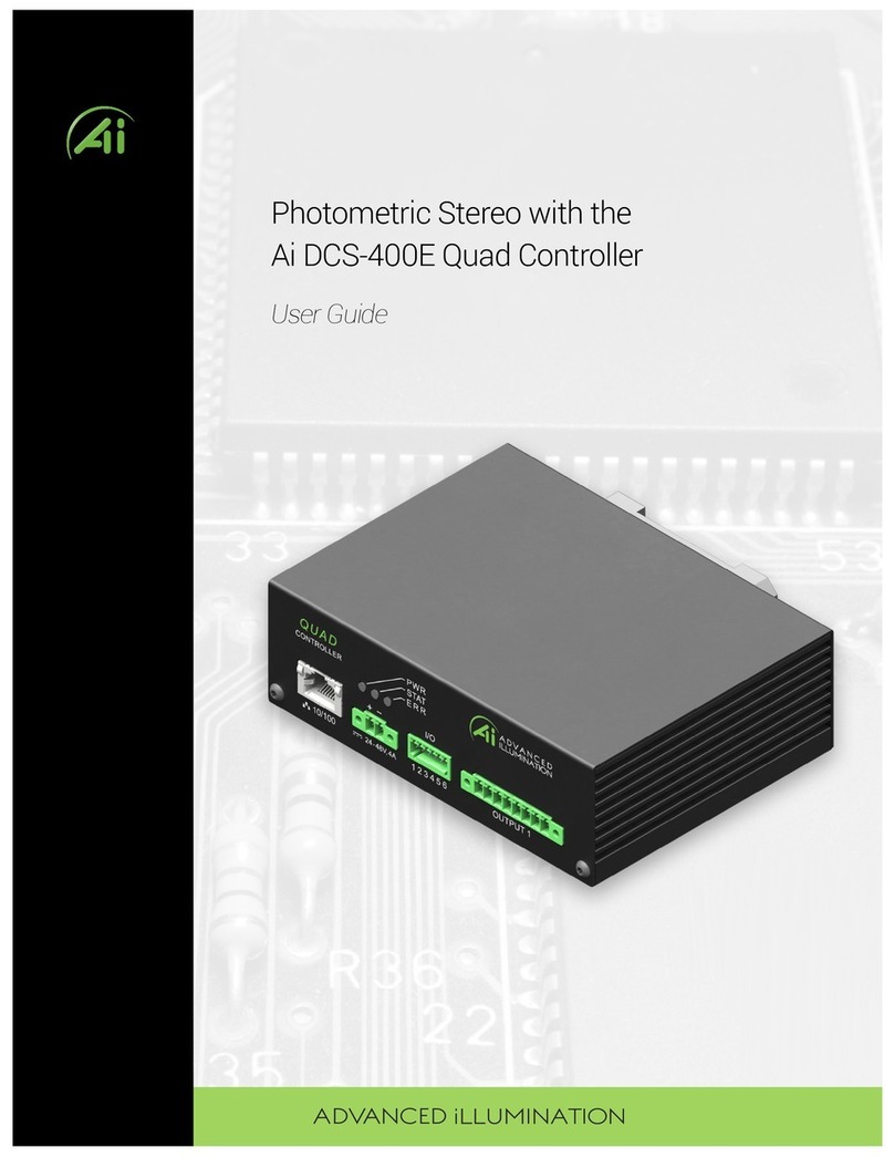
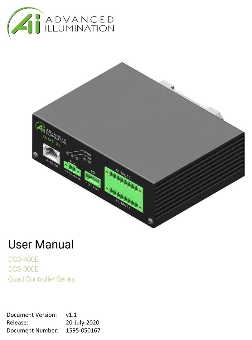
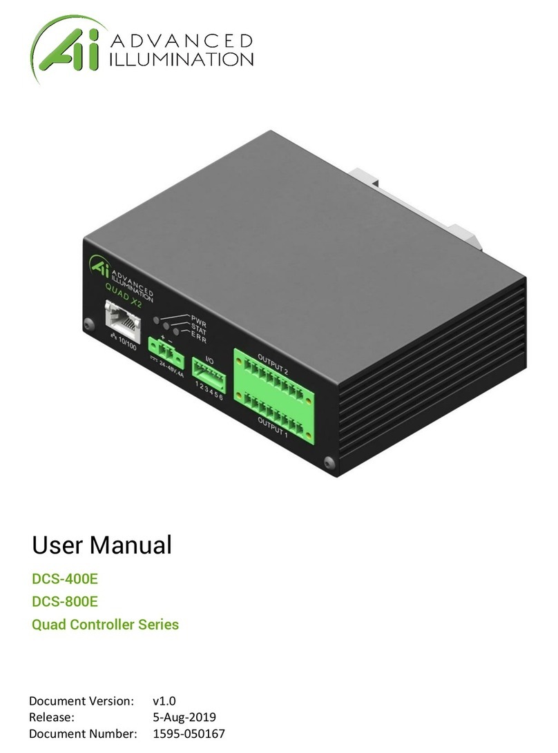
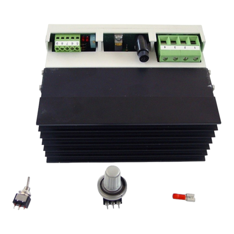
Advanced Illumination DCS Series User manual

1595-050143 REV 2.0
DCS Series Lighng Controller—User Manual
The manual includes information about the following:
DCS-100E, DCS-103E
Version information
V2.0 - Updated for DCS100 / 103E REVA 5/20/2019

DCS-Series User Manual 2 1595-050143 v2.0
Contents
Hardware Overview 3
DCS100 / DCS103 Overview 4
Dimensions / Mechanical 5
General Specicaon 6
Front Panel 7
Connecons
Power Input 8
Trigger Input 9
Trigger Diagram 10
Reserved Input 11
Output Connector Pinout and denion 12
Modes of Operaon 13
Quick Start 14
DHCP or Stac IP conguraon 14
GUI Installaon 15
Modes 16
Strobe vs. Connuous 17
Other features 18
Renaming Devices
Changing IP address
Ethernet Web Server
Ethernet Commands 19
Default Ethernet Sengs 19
Command List 20-23

DCS-Series User Manual 3 1595-050143 v2.0
Hardware Overview
The DCS Series lighng controller is a high-exibility controller for machine vision illuminators.
DCS-100E
• Single Independent Output,
• Up to 90W output power, 30W per channel
• 3-Independent Channels within output
Typical Applicaons
• Cost eecve single-light controller
• RGB or other mixed color Lighng
• Single-High Power Lighng; paralleled channel opera-
on provides high power output
DCS-103E
• Three Independent Outputs,
• Up to 90W output power, 30W per output
• 1-Independent Channel within each output
Typical Applicaons
• Cost eecve mul-light controller
• Drive a diverse range of dierent lights independently
• Drive mulple single-color light sources

DCS-Series User Manual 4 1595-050143 v2.0
DCS-100E — Overview
DCS-103E — Overview
Indicator LEDs / Reset Buon
10/100 Ethernet
Power Input (P1) Trigger Input (P2)
Integrated Din-
Rail Mounng
Foot
Power Input (P1) Trigger Input (P2) X3 Output / X1 Channel each

DCS-Series User Manual 5 1595-050143 v2.0
DCS-100E — Dimensions
DCS-103E — Dimensions

DCS-Series User Manual 6 1595-050143 v2.0
General Specicaons
Specicaon DCS-100E DCS-103E Notes
Power Requirements 24VDC Nominal, 4.5A —
Output Power Up to 90W, 30W per channel Up to 90W, 30W per output
Channel Control (3) Independent channels, (1) output
connector
(3) independent outputs, (1)
channel per output
Modes Connuous, Pulsed, or Gated Conn- —
External Trigger Input 5-30VDC compable, Opto-Isolated
inputs
—
Pulse Width Range 10usec - 10msec —Best performance 200usec
Trigger-to-Pulse Latency 10 usec —
Duty Cycle / Frequency 15% duty cycle limit in pulsed mode.
Maximum frequency 5000Hz.
—Maximum Frequency lim-
ited by type of light con-
nected to controller
Maximum Operang Temper-
ature Range
-10 to 125F —
Maximum Operang Temper- 135F —
Communicaon / Soware - 10/100 EthernetStandard TCP-IP,
UDP
- .NET library compable with C#,
etc..
—

DCS-Series User Manual 7 1595-050143 v2.0
Front Panel
Color Behavior Funcon
LED 1 Green On Main Power Indicator
LED 2 Amber Blink Once per second heartbeat when light is connected. Blinks faster
when commands are received.
LEDs 3,4,5 Yellow OFF / ON External trigger status. Blinks ON when Signal is HIGH
Buon SPST Push Push and Release Resets the device to factory sengs– Must be held for at least 5
seconds. Recommended to Power Toggle controller aer factory
DCS-103E
DCS-100E
34 5
1 2 LEDs
1
Reset
Output 3 Output 2 Output 1 x1 channel each
10/100 Ethernet
34 5
1 2 LEDs
1’
Reset
Output 1 x 3 channels

DCS-Series User Manual 8 1595-050143 v2.0
Connecons
Pin Funcon Note
1+24VDC 4.5A supply Recommended for best performance
2DC GND
3DC GND
4SHIELD Oponal: Tied to chassis copper for ESD/EMI protecon. Tie to earth
ground if desired.
Front View of Connector
1 2 3 4
Power Input—P1
DCS-103E
DCS-100E

DCS-Series User Manual 9 1595-050143 v2.0
External Trigger Input
Pin Funcon Note
1Trigger Common Connect to common ground of supply voltage based on sinking/
sourcing requirements. All triggers share common.
2Trigger Input 1 5-30VDC tolerant
3Trigger Input 2 —
4Trigger Input 3 —
Front View of Connector
DCS-103E
1 2 3 4
DCS-100E

DCS-Series User Manual 10 1595-050143 v2.0
Trigger Connecon Diagrams
PNP “Sourcing” Output
Trigger Input Schemac.
NPN “Open Collector” Sinking Output
Pin 1
Pin 2
Pin 3
Pin 4

DCS-Series User Manual 11 1595-050143 v2.0
Connector Pinout and C1 Cable Denions
Important Informaon
The connector is not for eld-use without explicit instrucon or assistance from Ai. A Signatech signal must be detected for the
outputs to be enabled. A “C1” part number with an Ai standard light will have the correct connector installed for compatability.
Signatech is a congured lighthead protecon scheme which is over-molded in standard “C1” cables.
Under normal operaon, pin 5 is read by the controller to determine informaon about the aached light head and safety lim-
its for current-drive.
Note:
Avoid cross-threading by inserng the cable straight and gently unl proper contact is made – the connector should thread in
smoothly with lile resistance. Do not force the connector if it doesn’t thread in smoothly.
*Do NOT connect anything to pin 5 – damage to internal electronics may occur if pin 5 is used for anything other than Sig-
natech protecon.
Female, B-Coded Receptacle
5 Posion M12
Pin “C1” Cable Conductor Col- Funcon
1Brown Channel 1, LED+
2White Channel 2, LED+
3Blue Channel Common, LED-
4Black Channel 3, LED+
*5 *SignatechTM SignatechTM Light Protecon

DCS-Series User Manual 12 1595-050143 v2.0
Modes of Operation
Continuous
Connuous mode provides connuous illuminaon at the desired current. Light is always on unless a user issues a command to
shut it o or the power is disconnected.
Power is limited by the type of light that is connected and by the total power dissipaon of the controller.
Limits are determined by SignatechTM. It is not required to manually limit sengs to protect the controller or light.
Strobe
Strobe mode illuminaon is triggered by an external signal.
Pulsewidths are available from 10usec to 64msec, and can be aached independently to each channel. Delay is available from
1us to 10ms.
Important Notes : Pulse Skipping and Idle behavior
When the maximum trigger frequency is exceeded, the controller will “skip” pulses in order to maintain a safe duty cycle. This
may appear as dark image acquisions (missed triggers) or unstable ickering. Double-check your frequency and compare it to
the maximum reported from the controller if this occurs.
Reduce your current or shorten your pulsewidth to increase the maximum frequency if required.
When the DCS controller is idle (no trigger acve) and in strobe mode, it may be possible to see a very small current visible in the
illuminator. This is normal behavior and ensures the illuminator will be at 100% capacity for the next trigger pulse.
Gated Connuous
This mode produces connuous illuminaon at the desired current, but the output follows the on-me of the external
trigger signal.
This mode is most useful to turn the light o during processes or in between inspecons, or when longer pulse widths
than pulsed mode will allow are needed.

DCS-Series User Manual 13 1595-050143 v2.0
Quick Start
Quick Start: To start with DHCP
Use this method if connecng through a network switch that automacally assigns IP addresses
Power the controller with the Ethernet cable connected to a network. The controller will automacally be assigned an IP ad-
dress by the network hardware.
The controller will default to using DHCP when it is available.
Oponal: Aer inially connecng to the controller, the user can supply a custom IP address by sending a UDP packet com-
mand with the new IP address. See the command table for proper usage of the commands.
If the user enters a custom IP address, it will begin using that address upon startup.
If a stac-IP address has been entered into EEPROM by a user, it will no longer use DHCP unless the EEPROM is cleared by a
“RESET” command, or the reset buon is pressed.
Quick Start: To start with a Static IP Address:
Use This Method if direct connecng to PC
Power the controller without an Ethernet cable connected, or connected directly to a PC. The controller will begin with a
default IP address of 192.168.0.1
Make sure the PC is using a STATIC IP connecon. To assign a stac IP in Windows, change your adapter sengs in your net-
work conguraon to use a stac ip under IPV4 Sengs.
The stac IP must be in the range of 192.168.0.XXX to work properly.
Typically it is NOT required to use a cross-over cable, but maybe necessary for older machines.

DCS-Series User Manual 14 1595-050143 v2.0
Quick Start: Graphical User Interface (GUI) Installation
Install the soware using the provided DCS-Setup applicaon.
Note: Installaon requires Microso .NET framework 3.5 or later.
Quick Start: Using the GUI
Pressing the devices drop-down box will ping the network for devices. The controller will scan for DCS controllers on the net-
work, and will display any devices found in the dropdown menu. Select your device and press “Test Connecon” to connect.
Manage Devices
The Manage Devices dialog can
be used to view informaon
about the controller or the
aached light.
Device can be renamed, or IP
address changed by entering
new data in the elds.

DCS-Series User Manual 15 1595-050143 v2.0
Quick Start: Enabling Modes
Select the mode for the specic channel with the drop-down box
All channels can operate in a mixture of any mode. There are no restricons.
Output current is governed by SignatechTM, which are current drive restricons implemented by Advanced Illuminaon.
Note the dierent current limits depending on the mode used.

DCS-Series User Manual 16 1595-050143 v2.0
Connuous vs. Strobe Operaon
Strobe mode provides higher current limits than connuous. Using SignatechTM we can overdrive the out-
put current higher. These values vary depending on the pulsewidth, current and type of light being used.
In Strobe or Gated-Connuous modes, the output is triggered by an external device. Strobe mode uses a
user-specied pulse-width and Gated-Connuous uses the input trigger width to determine the output
pulse width.
Pressing the “Pulse” buon will send a soware “trigger” command causing the light to pulse once.
For pulsewidth and delay the units “ms” and “us” can be entered for milliseconds and microseconds re-
specvely. Default units are msec.

DCS-Series User Manual 17 1595-050143 v2.0
Quick Start: Other Features
Renaming Devices:
Devices can be renamed by clicking the “Devices” text. The part number and listed devices will be shown when opening this
menu.
Changing the IP address:
In the “Manage Devices” window, enter the new IP address and press Enter, or TAB. The new IP address setting will not
take effect until the power is toggled to the controller.
Profiles:
Conguraon proles can be saved by selecng a prole number and pressing save. The proles switch immediately when se-
lecng a new one, so make sure your sengs are saved before switching to a new prole.
By default, the last-used prole will be enabled when the controller is switched on.
Ethernet WebServer
In the devices list, you can enable the WebServer and control the output from a standard internet browser. Aer enabling the
web server in the Soware GUI, you can access the built-in web server from most internet browsers by entering the IP address

DCS-Series User Manual 18 1595-050143 v2.0
Standard Ethernet Communication & Commands
Default Ethernet Settings
The Controller uses standard Ethernet protocol (TCP-IP and UDP) to communicate. The DCS control user interface can
be used to communicate, or other soware may be used to send data packets directly from the host to the controller.
Seng Value
Typical Port Sengs UDP, port 7777
TCP, port 777
DHCP Enabled by default
Default IP Address 192.168.0.1
*Controller will use default IP if DHCP fails upon
power up, or if an Ethernet cable is not connected
User Assigned IP Addresses User can assign a new IP address by sending a
command, or entering a new IP address in the
“manage devices” window of the GUI.
If a user assigned IP address is used, the controller
will not begin using that IP address unl the con-
troller power is toggled.

DCS-Series User Manual 19 1595-050143 v2.0
Command Structure
The DCS100 uses an SCPI-like interface where commands are a series of readable strings with parameters separated by
commas. The strings must be terminated by a semicolon (‘;’) for proper operaon.
Commands can be sent in an ASCII format by specifying the IP Address and correct port number for either TCP/IP or UDP.
Commands with a parameter
Commands that require a parameter have it separated by a comma.
Example: “SET:LEVEL, 100;”
Where “SET:LEVEL,” is the command and “100” is the parameter.
Commands without a parameter
If the command has no parameter, the command simply ends with a semicolon.
Example: “*IDN?;”
Commands are non-case sensive, and spaces may be used between commands and parameters for readability. Extra spac-
es will be ignored by the controller.

DCS-Series User Manual 20 1595-050143 v2.0
COMMAND
DESCRIPTION
RETURNS
“*IDN?;”
Gets device information: firm-
ware, hardware, etc..
Advanced illumination
“DCS-100: (fw version, hw version)”
“*CHANNEL:CONFIGS?;"
Reports the current, pulse-
width, delay, and trigger map
settings on all channels
Returns an XML formatted string:
“*PROFILE:NUMBER?;” Gets the active profile number
INFO: Profile “n” is currently ac-
tive.
"*PROFILE:NAMES?;" Gets all the profile names
saved in memory
Returns an XML formatted string:
<profiles><profile id="0" name="0" /
><profile id="1" name="1" /><profile
id="2" name="2" /><profile id="3"
name="3" /><profile id="4"
name="4" /><profile id="5"
name="5" /></profiles>
Information / Help commands
This manual suits for next models
2
Table of contents
Other Advanced Illumination Controllers manuals
