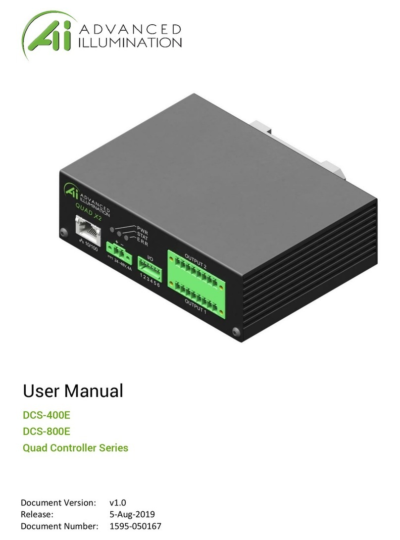
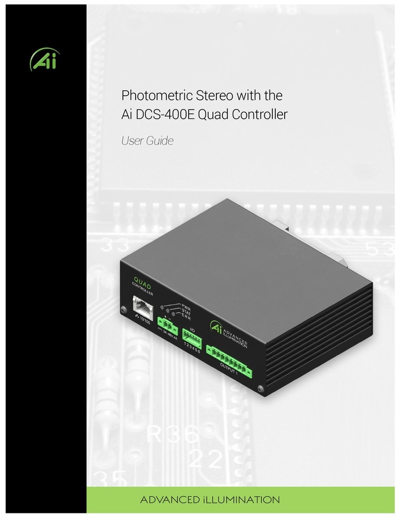
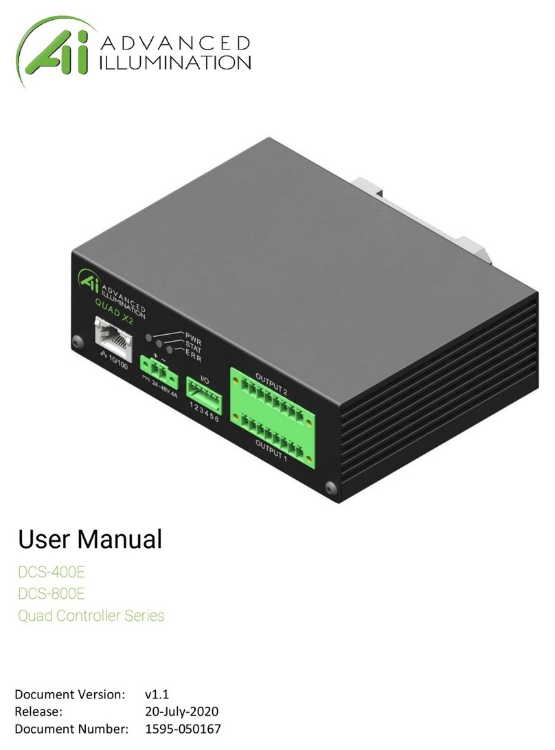
Advanced Illumination Pulsar 320 User manual

P u l s a r 3 2 0 M a n u a l
Pulsar 320
Strobe Controller
Operator’s Manual
& Installation Guide

a d v a n c e d i l l u m i n a t i o n . c o m P u l s a r 3 2 0 M a n u a l
P u l s a r 3 2 0 M a n u a l
The shipping container should contain the following items:
Packing List
Qty Ai Part #
1
2
1
1805314
1
1777989
Description
Pulsar 320 Controller
3 Pin,Trigger input connectors
2 Pin, Power input connector
USB Cable 172-1024
(x2)
(1)(1) (1)
2
A d v a n c e d i l l u m i n a t i o n , I n c.
2 4 P e a v i n e D r
R o c h e s t e r V T 0 5 7 6 7
8 0 2 . 7 6 7 . 3 8 3 0
050051 REV-03Manual, Operation, Pulsar 320

a d v a n c e d i l l u m i n a t i o n . c o m P u l s a r 3 2 0 M a n u a l
P u l s a r 3 2 0 M a n u a l
Pulsar 320 Controller
Operator’s Manual
Table of Contents
1.0 Introduction
1.1 Safety
1.2 Warranty
1.3 Return Policy
2.0 Features
2.1 Light Head Outputs
2.2 User Interface
2.2.1 Remote Operation
2.2.2 Local Control
2.3 Diagnostics
3.0 Quick Start
3.1 Pulsar 320 Controller Cable Connections
3.1.1 Power
3.1.2 Light Head
3.2 Pulsar 320 Status Indicator Lights
3.2.1 Green
3.2.2 Amber
3.2.3 Red
3.3 USB Control
4.0 Operation
4.1DenitionofTerms
4.1.1 Duty Cycle
4.1.2 Latency
4.1.3 Led and Light Head Characteristics
4.1.3.1 LED forward voltage
4.1.3.2 LED thermal resistance
4.1.3.3 LED voltage slope
4.1.3.4 Light head characteristics
4.1.4 Period
4.1.5 Pulse Width
4.1.6 Repetition Rate
4.1.7 Signatech II
4.1.8 Strobe modes
4.1.9 Trigger
4.1.10 Trigger Delay
3
. . . . . . . . . . . . . . . . . . . . . . . . . . . . . . . . . . . . . 6
7
8
12
. . . . . . . . . . . . . . . . . . . . . . . . . . . . . . . . . . . . . . . . .
. . . . . . . . . . . . . . . . . . . . . . . . . . . . .
. . . . . . . . . . . . . . . . . . . . . . . . . . . . . . . . . . . . .

a d v a n c e d i l l u m i n a t i o n . c o m P u l s a r 3 2 0 M a n u a l
P u l s a r 3 2 0 M a n u a l
4.2 Pulsar 320 Controller Cable Connections
4.2.1 Power
4.2.2 Trigger
4.2.3 Ethernet
4.2.4 USB
4.2.5 Light Head
4.3 Pulsar 320 Status Indicator Lights
4.3.1 Green
4.3.2 Amber
4.3.3 Red
4.4 Host Computer Control (Remote)
4.4.1 Software Installation
4.4.2 Running Under Host Computer Control
4.4.2.1 CongurePulsar320
4.4.2.2 Launch Pulsar 320 Controller User Interface
4.4.2.3 Pulsar 320 Utility Dialog Box Status Indicators
4.4.2.3.1 Light Head
4.4.2.3.2 USB Connection
4.4.2.3.3 Status Panels
4.4.2.4 Pulsar 320 User Interface Output Controls
4.4.2.4.1 Select Channel
4.4.2.4.2 Program Button
4.4.2.4.3 Mode
4.4.2.4.4 Control Settings
4.4.2.4.5 Protection
4.4.2.4.6 Triggers
4.4.2.4.7 Test
4.5 External Trigger Interface
4.5.1AlternateTriggerCongurations
5.0 Custom Programming
6.0 Troubleshooting
6.1 Pulsar 320 Status Indicator Lights
6.2 Error Codes
7.0 Specifications
8.0 Advanced Users Section
9.0 Appendix
A: Trigger Connection Diagram
B: Pulsar 320 Loader Utility
C: Installation Drawing
D: TCP/IP Setup Instructions
4
. . . . . . . . . . . . . . . . . . . . . . . . . . 25
25
27
31
32
. . . . . . . . . . . . . . . . . . . . . . . . . . . . . . . . .
. . . . . . . . . . . . . . . . . . . . . . . . . . . . . . . . . . .
. . . . . . . . . . . . . . . . . . . . . . . .
. . . . . . . . . . . . . . . . . . . . . . . . . . . . . . . . . . . . . . . .

a d v a n c e d i l l u m i n a t i o n . c o m P u l s a r 3 2 0 M a n u a l
P u l s a r 3 2 0 M a n u a l
Pulsar 320 Figures & Tables
5
List of Figures
Figure 1: Pulsar 320 front panel
Figure 2: 24V power supply connection
Figure 3: Pulsar 320 Light head output connection
Figure 4: Status indicator lights
Figure 5: USB dialog open
Figure 6: USB Connected
Figure 7: Ready to program test mode
Figure 8: USB Connection
Figure 9: Light Head Connection Diagram
Figure 10A: Software Installation Window
Figure 10B: Software Installation, Program Group
Figure 11A: GUI Dialog Window
Figure 11B: TCP/IP Dialog Window
Figure 11C: Settings Window
Figure 11D: Query Window
Figure 12: Trigger Connector
Figure 13: Trigger Pinout
Figure 14: S1, SW2 & SW3 locations
Figure 15: Trigger Connection Diagram
Figure 16: Cognex Connection Diagram
Figure 17: IPD Connection Diagram - Typical Trigger Wiring
Figure 18: IPD Connection Diagram -Vision Appliance, Relay/PLC Module
Figure 19: Pulsar 320 Loading Utility
Figure 20: Installation Drawings
Figure21:WindowsIPConguration
Figure 22: Local Area Properties
Figure 23: Internet Protocol Properties
Figure24:WindowsIPConguration
Figure25:USBPortConguration
Figure 26: Pulsar TCP/IP Connection and IP Dialog Window
List of Tables
Table 1: Light head output connector pin description
Table 2: Trigger connector pin description
Table3:Specications
Table 4: Internal switch functions
. . . . . . . . . . . . . . . . . . . . . . . . . . . . . . . . . . . . . . . . . . . 9
9
10
10
11
11
12
16
17
18
18
19
20
20
20
24
24
31
33
34
34
35
36
39
40
41
41
42
45
46
. . . . . . . . . . . . . . . . . . . . . . . . . . . . . . . . . . .
. . . . . . . . . . . . . . . . . . . . . . . .
. . . . . . . . . . . . . . . . . . . . . . . . . . . . . . . . . . . . . . . . . . .
. . . . . . . . . . . . . . . . . . . . . . . . . . . . . . . . . . . . . . . . . . . . . . . .
. . . . . . . . . . . . . . . . . . . . . . . . . . . . . . . . . . . . . . . . . . . . . . . .
. . . . . . . . . . . . . . . . . . . . . . . . . . . . . . . . . . . .
. . . . . . . . . . . . . . . . . . . . . . . . . . . . . . . . . . . . . . . . . . . . . . . .
. . . . . . . . . . . . . . . . . . . . . . . . . . . . . . . . . . .
. . . . . . . . . . . . . . . . . . . . . . . . . . . . . . . .
. . . . . . . . . . . . . . . . . . . . . . . . . . .
. . . . . . . . . . . . . . . . . . . . . . . . . . . . . . . . . . . . . . . . . . . .
. . . . . . . . . . . . . . . . . . . . . . . . . . . . . . . . . . . . . . . . .
. . . . . . . . . . . . . . . . . . . . . . . . . . . . . . . . . . . . . . . . . . . . . . . .
. . . . . . . . . . . . . . . . . . . . . . . . . . . . . . . . . . . . . . . . . . . . . . . . .
. . . . . . . . . . . . . . . . . . . . . . . . . . . . . . . . . . . . . . . . . . . . . . .
. . . . . . . . . . . . . . . . . . . . . . . . . . . . . . . . . . . . . . . . . . . . . . . . . . .
. . . . . . . . . . . . . . . . . . . . . . . . . . . . . . . . . . . . . . .
. . . . . . . . . . . . . . . . . . . . . . . . . . . . . . . . . . . .
. . . . . . . . . . . . . . . . . . . . . . . . . . . . . . . . . . . .
. . . . . . . . . . . . . . . . .
. .
. . . . . . . . . . . . . . . . . . . . . . . . . . . . . . . . . . . . . . . .
. . . . . . . . . . . . . . . . . . . . . . . . . . . . . . . . . . . . . . . . . . . .
. . . . . . . . . . . . . . . . . . . . . . . . . . . . . . . . . . . . . . .
. . . . . . . . . . . . . . . . . . . . . . . . . . . . . . . . . . . . . . . . . . . .
. . . . . . . . . . . . . . . . . . . . . . . . . . . . . . . . . . . . .
. . . . . . . . . . . . . . . . . . . . . . . . . . . . . . . . . . . . . . .
. . . . . . . . . . . . . . . . . . . . . . . . . . . . . . . . . . . . . . . . .
. . . . . . . . . . . . . . . .
17
24
26-29
30
. . . . . . . . . . . . . . . . . . . . . . . .
. . . . . . . . . . . . . . . . . . . . . . . . . . . . . . . . . . .
. . . . . . . . . . . . . . . . . . . . . . . . . . . . . . . . . . . . . . . . . . . . . . . . . . . . . . .
. . . . . . . . . . . . . . . . . . . . . . . . . . . . . . . . . . . . . . . . . . . .

a d v a n c e d i l l u m i n a t i o n . c o m P u l s a r 3 2 0 M a n u a l
P u l s a r 3 2 0 M a n u a l
1.0 Introduction
The Pulsar 320 Controller, used in conjunction with an external 24VDC
power supply, is a compact, 2 output, high power pulse (strobe only) current
sourceincorporatingawiderangeofexibilityinselectingtheoperating
parameters. The unit may be controlled and operated locally (with optional
local control interface) or remotely via a USB interface and host computer.
In addition, the unit employs built in Ethernet connectivity.
The balance of this manual contains the necessary operating instructions,
specicationsandotherdetailsrequiredtoallowtheusertoutilizethefull
capabilities of the Pulsar 320.
1.1 Safety
The Pulsar 320 is designed to protect Advanced illumination light heads
havingtheSignatechIorSignatechIIlightheadidenticationparameters.
WhenusinglightheadsconguredforSignatechI,anadaptercablemustbe
used to connect these lights to the Pulsar 320.
In certain modes of operation, the output voltages and currents provided by
the Pulsar 320 could result in a potentially injurious or fatal electrical shock.
For this reason, light heads should be connected BEFORE the
power switch is turned on. At no time should the operator touch the
output connector pins or light head leads when the power is on.
During normal operation, the Pulsar 320 may reach light head output
voltagesashighas100volts.Forspecicapplications,ortocomplywith
localcodes,thePulsar320maybeconguredtolimitthelightheadoutput
voltage to a maximum of 48 volts. Please contact Advanced illumination
whenthisrequirementexists.
Advanced illumination makes no warranty, expressed or implied, if
illumination or other devices produced by manufacturers other than
Advanced illumination are connected to the Pulsar 320.
1.2 Warranty
Every Advanced illumination, Inc. (Ai) product is thoroughly inspected and
tested before leaving the factory. Products are warranted to be free of
defects in workmanship and materials for a period of TWO YEARS from the
6

a d v a n c e d i l l u m i n a t i o n . c o m P u l s a r 3 2 0 M a n u a l
P u l s a r 3 2 0 M a n u a l
original date of purchase. Should a defect develop during this period, return
the complete product, freight prepaid, to one of Ai’s distributors or to the
Ai factory. Ai will inspect the unit, and if a defect is found will, at our option,
repair or replace the product without charge. Ai disclaims liability for any
implied warranties, including implied warranties or “merchantability” and
“tnessforaspecicpurpose.”
Aicannotbeheldresponsiblefortheunauthorizedorinappropriateuseof
our products.
NO LIABILITY FOR CONSEQUENTIAL DAMAGES.
InnoeventshallAdvancedillumination,Inc.beliableforconsequential,
special, incidental or indirect damages of any kind arising from the sale or
use of products.
1.3 Return Policy
Standard Products may be returned within 30 days of receipt of the order.
Products must be in resalable condition, in function and appearance, with
shipping charges prepaid. A restocking fee of 15% will be applied to all
items accepted for return to stock. If you need to make a return, please
call our Customer Service Department at 802.767.3830 x237 for a Return
MerchandiseAuthorization(RMA)number.Clearlymarktheoutsideof
the package with the RMA number.
NO RETURNS CAN BE ACCEPTED FOR STANDARD
VARIATION, CUSTOM VARIATION,AND CUSTOM
PRODUCTS.
Therearecurrentlyover100,000uniquecongurationsoftheAiproduct
line.Therefore,wecannotrestockalightbuilttoyourspecications.We
would be glad to help you order your light if you are unsure of the correct
partnumberoryourexactrequirements.
7

a d v a n c e d i l l u m i n a t i o n . c o m P u l s a r 3 2 0 M a n u a l
P u l s a r 3 2 0 M a n u a l
2.0 Features
The following is a brief overview of the features provided by the Pulsar 320.
These features will be covered in greater detail within the Operation and
Specicationsectionsofthemanual.
2.1 Light Head Outputs
Two outputs capable of high power are provided. Each will provide up to
50A of pulse current drive. The current of each channel is independently
selectable. Output pulse widths can be set between 1 and 100 milliseconds
in1microsecondincrementsatpulserepetitionratesupto400Hz.
2.2 User Interface
2.2.1 Remote Operation: Remote operation via a host computer
allowstheoperatortomakefulluseoftheexibilityofferedbythePulsar
320. Communication is accomplished by both a USB interface and Ethernet.
Operating parameters are set by user friendly Windows based Pulsar 320
controller software. Supported operating systems are Windows 2000,
Windows XP, and Windows Vista.
2.2.2 Local Control (future implementation): An optional local control
is available which allows complete control of all Pulsar 320 settings and
features. A 2X16 LCD display along with four front panel momentary
switches allows users to easily navigate the Pulsar 320’s many features and
set points.
2.3 Diagnostics
A comprehensive set of diagnostic routines and indicators are provided.
Error codes are displayed by the Pulsar 320 via LED indicators on the front
panel.Codedenitionsarefoundinsection6.0“Troubleshooting”where
diagnostics are covered in greater detail.
3.0 Quick Start
Thepurposeofthissectionistoallowtheoperatortoperformaquick
functional test. This will permit an easy checkout of the Pulsar 320 and
attached light head for proper operation.
8

a d v a n c e d i l l u m i n a t i o n . c o m P u l s a r 3 2 0 M a n u a l
P u l s a r 3 2 0 M a n u a l
3.1 Pulsar 320 Controller Cable Connections:
Two physical cable connections will be
requiredtooperatethePulsar320and
light head in self test mode. Figure 1
shows the front panel of the Pulsar 320.
3.1.1 Power: ThePulsar320requires
an external 24 volt supply for operation.
A power cable is provided. The black
wire is negative and the red wire is
positive. Plug the 2 pin connector
into the socket labeled “VDC INPUT”.
Observe the polarity markings on the
panel below theVDC INPUT socket.
Refer to section 4.2.1 for more details
regarding the 24 volt supply.
3.1.2 Light Head: Figure 3 shows how the output connectors on the
front panel of the Pulsar 320 mates with the light head connectors. Plug the
Figure 2: 24v Supply Connection
9

a d v a n c e d i l l u m i n a t i o n . c o m P u l s a r 3 2 0 M a n u a l
P u l s a r 3 2 0 M a n u a l
connector(s) from the light head(s)
into the 5 pin socket in the front of
the Pulsar 320 as shown in Figure 3.
3.2 Pulsar 320 Status Indicator
Lights:
The Pulsar 320 has three LED
indicator lights as shown in Figure 4
3.2.1 Green: This light indicates
that the Pulsar 320 has power either from the USB connection to the host
computer or the main 24VDC power connection.
3.2.2 Amber: The amber light indicates
the operational status of the Pulsar 320.
A blink rate of once per second indicates
normal operation. A blink rate of 5 times
per second indicates an error condition.
3.2.3 Red: The red light blinks an error
code in the case of an error condition.
The condition is indicated by three sets of
sequentialashes.Forexample:4ashes
followedby2ashesfollowedby3ashes
indicateanerrorcodeof423whichsignies
that the main power switch is off. Two common error codes are:
• 351: No light head detected.
• 423:The main power switch is off.
Refer to section 6.0 “Troubleshooting” for more detailed error code
information.
3.3 USB Control
1. Connect Pulsar 320 USB cable to host PC, 24vDC, and
applicable light head
2. Switch the main rocker power switch ON. A green power
LEDwililluminate,followedbyaashingamberLED.
10
Figure 3: Pulsar 320 Light Head
Output Connection
Figure 4: Status Indicator Lights

a d v a n c e d i l l u m i n a t i o n . c o m P u l s a r 3 2 0 M a n u a l
P u l s a r 3 2 0 M a n u a l
3. Launch Pulsar 320 Utility
4. Choose USB
5. Select a USB port. Use port 0 by default. Press Connect
6. Upon Connecting to a USB port, the strobe settings
window will open (Fig 6) - Grayed-out outputs mean
no light is connected.
7. Test the light head: Press SETUP radio button.
a. The light head should immediately enter a continuous current
mode that will allow for visible detection that the light is
working. This mode is useful for orientating the light in the
system.
b. This mode should NOT be used for inspection purposes as it
will provide indeterminate results.
c. Thismodemaymakethelightappeartoicker-thisisnormal.
11
Figure 6: USB Connected
Figure 5: USB Dialog Open

a d v a n c e d i l l u m i n a t i o n . c o m P u l s a r 3 2 0 M a n u a l
P u l s a r 3 2 0 M a n u a l
8. Test the light in TEST MODE
a. Press TEST radio button
b. Set Pulse Width slider to 1000
c. Set current to 10
d. Press PROGRAM
Thelightshouldashat10Hzwithnoexternaltriggerapplied.
At this point the attached light head(s) will be ON. Any further adjustments
can be made at any time using the same procedure as above. Adjusting PW
will change the duration of the output pulse, and adjusting CURRENT will
change the output level of the output pulse. Keep in mind that TEST mode
alwaysproducesa10Hzrepetitionratepulse.
The Pulsar 320 can communicate via ETHERNET. For instructions on
this, please refer to the TCP/IP setup guide in Appendix D.
4.0 Operation
The following section details the procedures for operation of the Pulsar 320
Controlleranddenesitsvariousoperatingmodes.
4.1 Denition of Terms
The following terms are used within this manual and, more generally, in
relation to machine vision illumination.
12
Figure 7: Ready to Program Test Mode

a d v a n c e d i l l u m i n a t i o n . c o m P u l s a r 3 2 0 M a n u a l
P u l s a r 3 2 0 M a n u a l
4.1.1 Duty Cycle: The ratio of the time the light head is “on” (pulse
width, Pw) to the time it is “off” (period,Tp). Calculated as (Pw / Tp) x 100.
The result is expressed in percent. The Signatech II feature of the Pulsar
320 allows the Pulsar 320 to limit the maximum duty cycle based on the
characteristics of the driven light head.
4.1.2 Latency: The time between the receipt of a trigger signal and
initiation of the output drive pulse. The latency is the sum of the rise-times
and propagation delays within the trigger processing circuitry. This time is
purposely kept to a minimum.
4.1.3 LED and Light head Characteristics: Many factors contribute
totheoperationalparametersofanLEDlighthead.TooptimizePulsar
320/light head operation, these characteristics are stored as part of the
information provided to the Pulsar 320 by the Signatech II circuit within
the light head. Some of the variables that affect how the light head can be
driven are outlined below.
4.1.3.1 LED Forward Voltage: The forward voltage drop across an LED
(VFWD) depends upon the nature of the semiconductor junction and the
currentthroughtheLED.ThespeciedVFWDforanLEDisusuallygiven
at its recommended operating current. Please note that when driven by
high current pulses,VFWD can increase by 10 to 20 times. For this reason
voltage levels at the Pulsar 320 output can be as high as 100 volts.
4.1.3.2 LED Thermal Resistance: A measure of temperature difference
between the LED junction and the LED connection to an external heat sink.
Overheating of the junction is the primary cause of failure in LEDs. The
value of the LED thermal resistance, combined with the heat sink thermal
resistance and the overall thermal time constant determine the maximum
pulse width, pulse current, and duty cycle of the light head.
4.1.3.3 LED Voltage Slope: The relationship between VFWD and the
forwardcurrentIFWD,usedbySignatechIItocalculatethevoltagerequired
to provide the desired current.
4.1.3.4 Light head Characteristics: Also contained within the data
provided by Signatech II to the Pulsar 320 are the number and type of LEDs
in each string and the number of parallel strings connected to each channel.
13

a d v a n c e d i l l u m i n a t i o n . c o m P u l s a r 3 2 0 M a n u a l
P u l s a r 3 2 0 M a n u a l
4.1.4 Period: The length of time between two successive pulses or the
reciprocalofthepulsefrequency.
4.1.5 Pulse Width: The length of time the light head is activated by the
Pulsar 320. This is typically measured between the 50% amplitude points of
the pulse.
4.1.6 Repetition Rate: The rate at which successive pulses are initiated.
Alsoknownasfrequency,whichismeasuredinHertz(cyclespersecond).
Repetition rate is usually multiple times per second.
4.1.7 Signatech II: A proprietary feature of Ai light heads and the Pulsar
320. SignatechidentiesthetypeoflightheadconnectedtothePulsar320
and maintains safe operating limits for each type. The Pulsar 320 can be set
so that Signatech preferentially limits pulse current, pulse width, or period to
remain within the safe power dissipation range of the light head.
4.1.8 Strobe Modes:Thestrobemodeisusedto“freeze”amovingitem
at a particular moment in time. Typically, with LED illumination sources,
the strobe mode involves driving the light head with a high current, short
duration pulse. This provides a very intense light output pulse. As long as
the duty cycle is kept short, no damage to the LEDs occur as a result of the
high current.
4.1.9 Trigger: The signal which initiates an output from the Pulsar 320 to
the light head. The trigger signal is normally generated by an external source
such as a camera or other sensor. Several modes of trigger operation are
provided for in the Pulsar 320. The trigger may start on either a rising or
falling edge. For test purposes, the Pulsar 320 also has an internal trigger
source.
4.1.10 Trigger Delay: Certainapplicationsrequirethataknown,xed
time elapse between the receipt of a trigger signal and the initiation of
an output pulse.This is the trigger delay. For example, if the trigger signal
is received from a position sensor, prior to the arrival of the item to be
inspected, a delay to account for that transit time would be introduced. If
the trigger signal originates from the camera at the start of the shutter
opening, a short delay might be introduced to assure the shutter is fully
open or that the illumination pulse occurs elsewhere within the frame time.
14

a d v a n c e d i l l u m i n a t i o n . c o m P u l s a r 3 2 0 M a n u a l
P u l s a r 3 2 0 M a n u a l
4.2 Pulsar 320 Controller Cable Connections
Four physical connections, one of which needs to be a USB or Ethernet will
berequiredtooperatethePulsar320andlighthead.Referbacktogure1
for an illustration of the Pulsar 320’s front panel.
4.2.1 Power: The input power connector is located near the bottom
centerofthePulsar320’sfrontpanel.ThePulsar320requiresanexternal
24voltsupplyforoperation.Thepowersupplyneedstohavesufcient
amperage rating to drive the light head in the desired mode of operation.
Advanced illumination recommends a minimum of 4A for full output
operation. A power cable is provided.The black wire is negative and the red
wire is positive. Plug the 2 pin connector into the socket labeled “INPUT”.
Observe the polarity markings on the right hand side of the connector
socket.
4.2.2 Trigger: The trigger input connectors are located at the upper right
of the Pulsar 320’s front panel. The differential trigger levels are CMOS/TTL
compatible but will accept input pulses as great as 30 V. Two input trigger
connectors are provided, one for each output. One trigger may be mapped
to both outputs. For more detailed triggering information refer to section
4.6 “External Trigger Interface”.
4.2.3 Ethernet: An RJ45 connector is located to the lower right of the
front panel and is provided for Ethernet connectivity. Standard protocols
supported are TCP/IP, UDP,TFTP via 10/100Base-T. For more detailed
information on Ethernet connectivity.
4.2.4 USB: The USB connector is located to the right and center of the
front panel.A host computer will communicate with the Pulsar 320 via
this USB connection. Connect the provided USB cable between the USB
connection on the host computer and the connector labeled USB on the
Pulsar 320. The Pulsar 320 is Microsoft HID USB compliant. Therefore, a
host computer with Windows 2000, Windows XP or Windows Vista will
auto-detect the Pulsar 320.
Figure 6 is a connection diagram for the output connector. Connect light
head(s) in accordance with Figure 6.
4.2.5 Light Head: Power to light heads is supplied by two independent
connectorsonthefrontpaneleachhaving5pins.Table1identiesthe
15

a d v a n c e d i l l u m i n a t i o n . c o m P u l s a r 3 2 0 M a n u a l
P u l s a r 3 2 0 M a n u a l
function of each pin for the 5 Pin power connector. Plug the connector
from each light head into the 5 pin socket as shown in Figure 3.
4.3 Pulsar 320 Status Indicator Lights
ThePulsar320hasthreeLEDindicatorlights.Referbacktogure4foran
illustration of these indicator lights.
4.3.1 Green: This light indicates that the Pulsar 320 has power either
from the USB connection to the host computer or the main 24VDC power
connection.
4.3.2 Amber: The amber light indicates the operational status of the
Pulsar 320. A blink rate of once per second indicates normal operation. A
blink rate of 5 times per second indicates an error condition.
4.3.3 Red: The red light blinks an error code in the case of an error
condition.Theconditionisindicatedbythreesetsofsequentialashes.For
example:4ashesfollowedby2ashesfollowedby3ashesindicatesan
errorcodeof423whichsigniesthatthemainpowerswitchisoff.Two
common error codes are:
•351: No light head detected.
• 423:The main power switch is off.
Refer to section 6.0 “Troubleshooting” for more detailed error code
information.
4.4 Host Computer Control (REMOTE)
T
otakefulladvantageoftheexibilityof
the Pulsar 320, software is provided which
permits the operating parameters to be set
by a host computer. The host computer
will be connected to the Pulsar 320 via a
USBportutilizingaUSBTypeBconnector.
(See Figure 7) The USB port is Microsoft
HID compliant.
16
Figure 8: USB Connection

a d v a n c e d i l l u m i n a t i o n . c o m P u l s a r 3 2 0 M a n u a l
P u l s a r 3 2 0 M a n u a l
Figure 9: Light Head Connection Diagram
Table 1: Pin Function Chart
17

a d v a n c e d i l l u m i n a t i o n . c o m P u l s a r 3 2 0 M a n u a l
P u l s a r 3 2 0 M a n u a l
4.4.1 Software Installation: Pulsar 320 Controller user interface
softwareisrequiredtosettheoperationalparametersofthePulsar320.
This utility program is included online at our website, and is installed as
follows:
Note:AdministratorAccesstothesystemisusuallyrequiredtoinstall
thesoftware.
Note: Supported operating systems are Windows XP through Windows
10.
1. The software can be found on our website under: Resources ->
Downloads -> Software -> Pulsar 320 Control Software.
2. Select setup.exe.
Figure 10A: Software Installation Window
Figure 10B: Software Installation, Program Group
18

a d v a n c e d i l l u m i n a t i o n . c o m P u l s a r 3 2 0 M a n u a l
P u l s a r 3 2 0 M a n u a l
3. Close all open applications if prompted and press OK.
4. Select a Program Group or use the default (Advanced Illumination) and
clickNext.(Seegure10B.)
Note: If for some reason the automatic installation program cannot be used,
the software can be manually installed as follows: Place the four support
lesfrom the downloads in the same folder on the PC.
1) MPDH8USB_TCP.dll
2) PulsarAPI.dll
3) Pulsar320Loader.exe
4.4.2 Running under Host Computer Control
4.4.2.1 Congure Pulsar 320: ThePulsar320comespre-congured
for normal use. See section 8 “Advanced User Section” for a complete
descriptionofoptionalcongurations.
4.4.2.2 Launch Pulsar 320 Controller user interface: To run the
program; go to Start -> Programs -> Advanced illumination -> Pulsar
Controller. Upon execution of the Pulsar Controller Utility program, the
dialogboxshowningure11Awillappear.
GUI Dialog Descriptions
A. OpenDialog:Openssavedconguration
B. SaveDialog:SavesactivecongurationtohostPC
C. USB: Opens USB connection dialog
19
Figure 11A: GUI Dialog Window

a d v a n c e d i l l u m i n a t i o n . c o m P u l s a r 3 2 0 M a n u a l
P u l s a r 3 2 0 M a n u a l
D. TCP/IP: Opens TCP/IP connection dialog
E. Settings:OpensPulsar320congurationsettingsdialog
1. Slew Rate: used to reduce output ripple/ringing on the output
light pulse. Using the proper slew rate setting may improve
lighting performance.
a. High: (default) Used when pulsing below 100uSec
b. Mid-High: Used when pulsing 100 - 500uSec
c. Mid-Low: Used when pulsing 500 - 1000uSec
d. Low: Used when pulsing >1000uSec
2. Differential Trigger: Default checked. Activates the differential trigger
inputs. Recommendation is to leave this on unless otherwise
instructed.
3. Advanced Settings: 48V output limit.
Default unchecked. Apply this setting
to clamp the output strobe voltage to
48V. This may reduce performance
signicantlyforcertainlightsources.
F. Query: Displays device information
Edit Network button allows for TCP/IP and
networkcongurationtooccurforthedevice.
20
Slew Rate
Settings
Channel 1
Channel 2
High
High
Differential Trigger
Trigger 1
Trigger 2
Advanced Settings
Limit Output to 48V
Set Close
Address
IPDialog
High
OK Cancel
Subnet
High
Gateway
High
Figure 11B: TCP/IP Dialog Window
Figure 11C: Settings Window
Device
Query
HW Version
FW Version
Network
IP Address
Edit Network OK
Serial Number
7200-000186-110
8200-000219-113
0000000235
Subnet Mask
Gateway
MAC Address
192.168.24.99
255.255.255.0
192.168.24.1
DA:8E:00:00:00:33
Figure 11D: Query Window
Table of contents
Other Advanced Illumination Controllers manuals
Popular Controllers manuals by other brands

National Instruments
National Instruments NI cRIO-9022 User manual and specifications
Chino
Chino CP350 Series instructions
UTC Fire and Security
UTC Fire and Security Interlogix TruPortal TP-SYS-BRD quick reference

Clauss
Clauss CIRCON 4260007480120 manual
Standa
Standa 8SMC1-USBhF user manual

SICK
SICK MSC800 operating instructions
