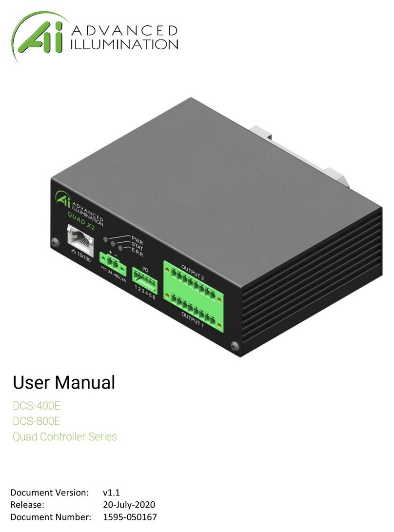
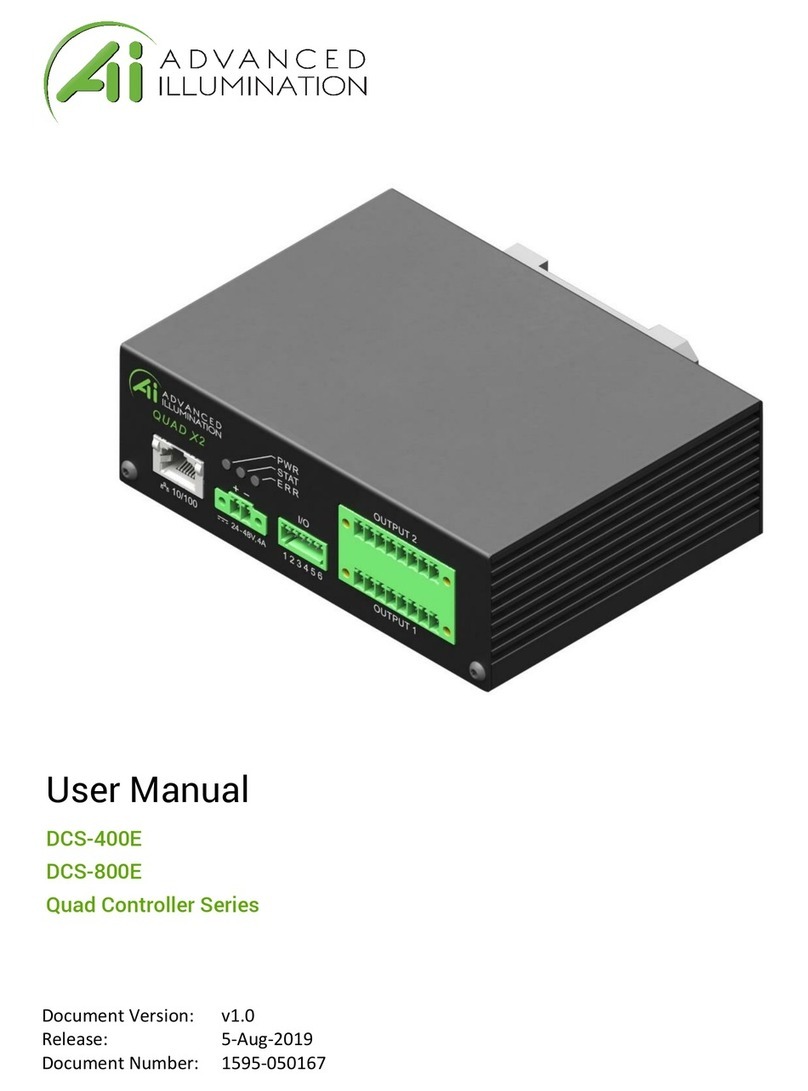
Advanced Illumination DCS-400E User manual

Photometric Stereo with the
Ai DCS-400E Quad Controller
User Guide

Mounting Bracket
DIN Rail Compatible
Input Power
24 V DC Nominal, 4.5 A
Vmin = 22 V DC
Vmax = 48 V DC
External Trigger
Input/Output
5V, TTL Compatible
Overtvoltage Protected,
Safe up to 30 V DC
Communication/Software
10/100 Ethernet Standard TCP-IP, UDP
.NET Library Compatible with C#, F#, and VB
Windows Software
Channel Control
DCS-400E: 4 Independent Channels, 1 Output
DCS-800E: 8 Independent Channels, 2 Outputs

Introduction
Hardware & Setup
Hardware Overview
Setup Diagram
DCS-400E & DCS-800E General Specs
DCS 400E Overview
Modes
Standard
Sequenced
Connections
Camera Setup
Design Assistant Software Setup
Application Examples
Threaded Metallic Part Inspection
Glossy Vitamin Bottle Inspection
2
2
2
3
3
4
4
4
5
6
6
7
8
8
9
Table of Contents
Page 1

Hardware Overview
Hardware & Setup
The following hardware are used in the examples featured in this user guide.
DCS-400E
Quad Controller
DF198 Dark Field Ring Light
DF198-WHIQ1
USB 3 Camera
Standardized Camera Interface
MIL Compatible
Introduction
Challenging machine vision inspection requirements often call for more sophisticated imaging
techniques, like those employed with Photometric Stereo. The DCS-400E (Quad Controller,
4-channel) and DCS-800E (Quad X2, 8-channel) lighting controllers provide multi-channel
lighting and sequenced, multi-image captures that produce compelling inspection results when
processed with photometric stereo imaging software libraries.
A typical photometric stereo imaging application uses two or more channels of lighting to
sequentially illuminate the target from different directions. The DCS-400E and DCS-800E allow
up to 4 or 8 potential channels, respectively, which can be used in any combination of quadrants
or colors, or even different light types. To meet the inspection requirements, these combinations
can be mixed and matched to create the ultimate multi-dimensional lighting effects.
The Quad Controllers allow independent brightness, pulse width, and pulse delay across all
channels, affording maximum flexibility. Congurable output signals are available to provide
frame start and stop control over the camera, as well as the ability to save and load channel
recipes on the fly.
Page 2

Trigger Setup Diagram
Camera
External Trigger
24 V DC
Trigger
Connector
Q1 Connector
X4 / X8 Channels
SignaTechTM EEPROM
DCS-400E Quad Controller
or DCS-800E Quad X2
Vision Software
Q1 Light
Single Cable, up to
4 Channels per Connector
DCS-400E & DCS-800E Specications
Modes
Power Requirements
Output Power
Pulse Width Range
DCS-400E
500mA Continuous per Channel; Up to 50W Total,
5A Pulsed per Channel; 12.5W per Channel
24V DC Nominal, 4.5A Maximum
Pulsed, Continuous, Gated Continuous
30 μsec - 3600 msec
DCS-800E
Strobe Frequency Limit
2KHz
Trigger Latency
30 μsec Typical
Channel Control
8 Independent Channels,
2 Outputs
4 Independent Channels,
1 Output
500mA Continuous per Channel; Up to 100W Total,
5A Pulsed per Channel; 12.5W per Channel
Download the User Manual for the DCS-400E & DCS-800E here:
https://www.advancedillumination.com/quad-controllers-manual
Page 3

Standard mode works like a traditional strobe controller where all channels re with a xed delay
and pulse width. There is no modied channel sequencing that occurs, and all channels re from
a single trigger edge.
Figure 1 - DCS-400E Standard Channel Settings, Single Event. If using DCS-800E, Channels 1-8 will be visible.
Modes: Standard
Figure 2 - A Single Trigger Flashes each channel, with or without independent delay. Note: delay is not to scale with the
channel settings shown in Figure 1.
DCS-400E Overview
Page 4

Sequenced mode allows the user to synchronize each channel flash with a camera exposure
to create a multi-dimensional acquisition. Channel recipes can be congured by the user,
depending on the application needs.
A Sequence is made up of a series of Events. Events can be thought of as "recipes" that contain
all the channel settings (pulse delay, current, pulse width, etc.) associated with the receiving
trigger.
With the DCS-400E, each Event can include anywhere from 1-4 channels (DCS-800E includes 1-8
channels), with their respective settings (pulse delay, current, pulse width). For example, to set
up a quadrant imaging application, the user should create x4 Events, one for each quadrant. An
Event can contain any number of channels.
The example Sequence in Figure 3 shows Event 2 thru 5 in its series. This setup will require x4
triggers from the camera to complete the Sequence.
Figure 3 - Dening a Sequence using four Events with the DCS-400E .
Figure 4 - Visual representation of each trigger initiating the next Event in the Sequence.
Modes: Sequenced
Page 5

Basic Camera to LC (Light Controller) Connections.
Figure 5 - Camera Exposure Triggers LC Channels.
Connections
Figure 6 - LC Triggered Externally, Frame-Start Triggers Camera Exposure.
In the following examples, we are using a typical USB 3.0 camera with Matrox Design Assistant.
The Quad Controllers are compatible with any camera and software combination that is capable
of Photometric Stereo.
Camera Setup
Page 6

The full extent of using Matrox Design Assistant is beyond the scope of this User Guide.
However, included in this document is a broad overview of how the DCS-400E Quad Controller
and Ai lights work in conjunction with the Photometric Stereo library functions.
Visit this URL to Access the Matrox MIL:
https://www.matrox.com/imaging/en/products/software/design-assistant-machine-vision-software/
Design Assistant Software Setup
Page 7

The following threaded metallic part presents a challenge for standard vision light and camera
congurations. The varying heights of the object’s threads create signicant shadowing, making
it very difcult to visually inspect for defects. The metallic surface also presents a challenge
with unwanted specular reflections. We independently control the quadrants of a DF198-115
MicroBriteTM Diffuse Ring Light with the DCS-400E Quad Controller to illuminate the threaded part
from four directions.
The input images in Figure 7 highlight the inspection challenges created by the shadowing
and reflections of the part’s 3D surface characteristics. However, by processing the images in
the Matrox Design Assistant and Imaging Library, the nal flattened shape image removes the
specular reflections and severe shadowing. This results in an image more easily inspected for
damaged threads or other imperfections.
Application Examples
Figure 8 - MIL Operator View.
Figure 7 - Input images of the inspected threaded metallic part.
Threaded Metallic Part Inspection Example
Page 8

In this example, we are inspecting a printed lot code on the bottom of a bottle. Due to the
reflective and concave characteristics of the bottom of the bottle, it is difcult to illuminate the
printed lot code without excessive specular reflections.
However, by using a DF198 MicroBriteTM Diffuse
Ring Light with each of its four quadrants
independently controlled with the DCS-400E Quad
Controller, we are able to capture four images with
illumination at the same angle of incidence, but
from multiple directions.
Using the Matrox Design Assistant and Imaging
Library (MIL) to process the images, the nal
albedo of the image is flat – resulting in an easily
identiable printed lot code.
Figure 9 - Input images of the glossy vitamin bottle.
Figure 10 - Final processed image.
Glossy Vitamin Bottle Inspection Example
For additional application examples and detailed Photometric Stereo information, visit our website:
https://www.advancedillumination.com/photometric-stereo-technique/
Page 9

www.advancedillumination.com | 440 State Garage Rd., Rochester, VT 05767
Other manuals for DCS-400E
1
This manual suits for next models
1
Table of contents
Other Advanced Illumination Controllers manuals
Popular Controllers manuals by other brands
Intel
Intel 845PE Thermal Design Guide

Kübler
Kübler 573 Series operating instructions

Heatcraft Refrigeration Products
Heatcraft Refrigeration Products 25001501 Installation & operating instructions
Sony
Sony JunboTron JME-SA200 operating instructions
Cypress
Cypress UNIVERSAL CAPSENSE quick start guide

Weathermatic
Weathermatic PROLINE PL800 owner's manual
