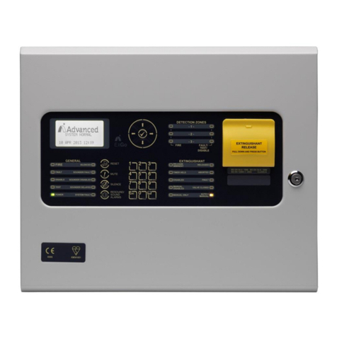
Advanced Mx Pro 4 User manual

Zonal LED Indicators
The operation and functions described in this manual are available from Software Version 4000-016-00 onwards.
The zonal LED indicator cards are a range of panel mounted peripheral modules that can be added to the
MxPro 4 series of control panels. The cards are available in numerous configurations and provide individual
indication of the zone(s) in fire. The units fully support the MxPro 4 systems DynamiX zoning facilities on
networked or larger stand-alone systems and can be used to provide individual zonal LED indication at one
location.
The Mxp-024F and Mxp-025F are 20 zone units, which are fitted to the front display plate on an MxPro 4
series control panel. The Mxp-013-050F, Mxp-013-100F and Mxp-200F incorporate 50, 100 or 200 LED
indicators respectively and are compatible with all of the MxPro 4 series multi-loop panels. The zone range on
the 100 way card can be assigned using an on board DIL switch and multiple cards can be placed in banks to
allow indication of up to 1000 zones using standard units.
The cards are capable of simultaneously displaying all zones in a fire condition and incorporate a unique
power saving feature to minimise the power drawn from the control panel in the event of a major fire. Several
other options are also available within the MxPro 4 range for an application where indication of fire signals
from zones in addition to the panels’ graphical display is required. These options include Advanced Mimic
Units, graphics systems and printers.
Insert Image
www.acornfiresecurity.com

Specifications & Ordering:
Models, Sales Order Parts:
Part No:
Mxp-024F: 20 Zone LED Card and label fitted to a Mx-4100 control panel
Mxp-025F: 20 Zone LED Card and label fitted to an Mx-4200, Mx-4400 or Mx-4800
Mxp-013-050: 50 Zone LED Card and label fitted to an Mx-4200, Mx-4400 or Mx-4800.
Mxp-013-100: 100 Zone LED Card and label fitted to an Mx-4200, Mx-4400 or Mx-4800
Mxp-013-200: 2x 100 Zone LED Cards and label fitted to an Mx-4200, Mx-4400 or Mx-4800
Spares:
Mxs-024: Replacement 20 Zone LED Card (PCB only)
Mxs-009-050: Replacement 50 Zone LED Card (PCB only).
Mxs-009-100: Replacement 100 Zone LED Card (PCB only).
Applications / Limitations:
The zone indicator card can be fitted to an MxPro 4 control panel to provide indication of the zone(s) in fire in
addition to the panels graphical display. The LED will illuminate when the corresponding zone enters a fire
condition.
The 100 Zone LED card incorporates a DIL switch to set the zone range to be indicated from 1 to 1000. (E.g. 1
–100, 101 –200…901 –1000). The 20 and 50 zone cards display zones 1 –20 and zones 1 –50 respectively.
In the event of more than 50 zones entering a fire condition, the LED’s will change from continuous to flashing
in order to minimise the power drawn from the control panel.
If an Mxp-012 on-board printer is fitted to a panel, and a zone indicator card is also required, use the Mxp-013-
050, Mxp-013-100 or Mxp-013-200 modules. The Mxp-025 20 zone LED card cannot also be used.
Compatibility:
The Mxp-024F can be fitted to an Mx-4100 control panel.
The Mxp-025F, Mxp-013-050F, Mxp-013-100F and Mxp-013-200F can be fitted to an Mx-4200, Mx-4400 or
Mx-4800 control panel.
All Zone Indicator cards are supported from panel software revision 16 onwards.
Item
Specification Details
Panel loading in
Quiescent state
3mA
Panel loading, all
LEDS on
Mxp-024F / Mxp-025F
Mxp-013-50F / Mxp-013-100F
Mxp-013-200F
12mA
27mA
54mA
Maximum Working
Temperature
50°C
As our policy is one of constant product improvement the right is therefore reserved to modify product specifications without prior notice
www.acornfiresecurity.com

3
Table of Contents Page
1INSTALLATION..............................................................................................................................................4
1.1 MXP-024F ...............................................................................................................................................4
1.2 MXP-025F ...............................................................................................................................................4
1.3 MXP-013-XXXF.......................................................................................................................................5
1.3.1 Mxp-013-050 / Mxp-013-100..............................................................................................................5
1.3.2 Mxp-013-200......................................................................................................................................5
2CONFIGURATION..........................................................................................................................................6
3OPERATION:..................................................................................................................................................6
3.1 TESTING THE ZONAL LED INDICATORS......................................................................................................6
www.acornfiresecurity.com

4
1 Installation
The Zonal LED Indicator Cards are normally factory fitted options. These instructions cover the installation,
replacement and configuration of spare assemblies.
Isolate ALL sources of power before installing or removing printed circuit
boards.
1.1 Mxp-024F
The Mxp-024F is mounted on the chassis fascia plate using 4x M3 screws.
To replace a card:
a) Unplug the ribbon cable from the LED card.
b) Remove the 4x nuts and remove the card. Be
careful not to lose the spacers.
c) Fit the replacement card (Mxs-024) and fix in
place with the 4x nuts.
d) Re-connect the ribbon cable to the LED card.
e) Test the LED operation (refer to Operation
Section).
Mxs-024
Interconnecting
Cable
Display Card
4x M3 Nut
NOTE: If a network interface card (Mxp-003 or Mxp-009) is required and fitted, this is installed on top of the LED
card using spacers.
1.2 Mxp-025F
To replace a card:
a) Unplug the ribbon cable from the LED card.
b) Remove the 4x nuts and remove the card.
Be careful not to lose the spacers.
c) Fit the replacement card (Mxs-024) and fix
in place with the 4x nuts.
d) Re-connect the ribbon cable to the LED
card.
e) Test the LED operation (refer to Operation
Section).
Mxs-024
Interconnecting
Cable
Display Card
4x M3 Nut
www.acornfiresecurity.com

5
1.3 Mxp-013-XXXF
The Mxp-013-050, Mxp-013-100 and Mxp-200 are mounted onto a fascia plate on the door. The cards are
attached to the fascia plate using 6 nuts.
1.3.1 Mxp-013-050 / Mxp-013-100
To replace a card:
a) Unplug the ribbon cable from the LED card.
b) Remove the 6x nuts and remove the card. Be careful not to lose the spacers.
c) Fit the replacement card (Mxs-013-050 or Mxs-013-100 as appropriate) and fix in place with the 6x nuts.
d) Re-connect the ribbon cable to PL1 position.
e) Check the configuration of the Zone range (refer to Configuration Section).
f) Test the LED operation (refer to Operation Section).
1.3.2 Mxp-013-200
The Mxp-013-200 consists of 2x 100 LED Indicator cards mounted on the fascia plate and connected together
using an interconnecting ribbon cable.
To replace a card:
a) Unplug the appropriate ribbon cable(s) from the LED card.
b) Remove the 6x nuts and remove the card. Be careful not to lose the spacers.
c) Fit the replacement card (Mxs-013-100) and fix in place with the 6x nuts.
d) Re-connect the ribbon cable to the appropriate positions.
e) Check the configuration of the Zone range (refer to Configuration Section).
f) Test the LED operation (refer to Operation Section).
www.acornfiresecurity.com

6
2 Configuration
The Mxp-024 and Mxp-025 are pre-configured to show zone numbers 1…20.
The Mxp-013 can be configured from a DIL switch to any of the zone ranges in the table below.
DIL switch (SW1) settings
Zone Range
(Note 1)
4
3
2
1
Off
Off
Off
Off
1 - 100
Off
Off
Off
On
101 - 200
Off
Off
On
Off
201 - 300
Off
Off
On
On
301 - 400
Off
On
Off
Off
401 - 500
Off
On
Off
On
501 - 600
Off
On
On
Off
601 - 700
Off
On
On
On
701 - 800
On
Off
Off
Off
801 - 900
On
Off
Off
On
901 - 1000
On
On
On
On
Test Mode
Notes:
1. Mxp-013-050 indicates the first 50 zones in each of the ranges.
3 Operation:
When a zone changes state to a fire condition, the corresponding zone LED will illuminate. The Zone LED
Indicators will be turned off when the panel is manually reset.
The Mxp-013 incorporates a power saving feature so that in the event of a major fire with more than 50 zones
all in a fire condition occurring in the same zone range, the zone LED’s will change from being continuously on
to flashing in order to minimise power drawn from the standby battery.
3.1 Testing the Zonal LED Indicators
Enter the “TEST” menu and select “DISPLAY”. All of the zonal LED’s will then flash on and off for several
seconds.
www.acornfiresecurity.com
This manual suits for next models
5
Table of contents
Other Advanced Control Panel manuals
Advanced
Advanced LIFELINE Px-100 User manual

Advanced
Advanced Lux Intelligent LX-9400 User manual

Advanced
Advanced LIFELINE Px-100 User manual

Advanced
Advanced Ex-3001 User manual

Advanced
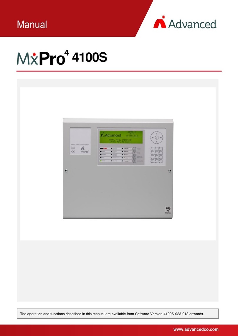
Advanced MxPro 4 4100S User manual
Advanced
Advanced Quick Zone XL Guide
Advanced
Advanced MxPro4 Mx-4200 User manual
Advanced
Advanced ExGo Series User manual
Advanced
Advanced MxPro4 Series User manual

Advanced
Advanced Mx-5101xR User manual