Advanced LIFELINE Px-100 User manual

www.advancedco.com
Paging Control
Product Manual
The operation and functions described in this manual are available from Software Version PX100-001-00 onwards.

www.advancedco.com
Item
Specification Details
Enclosure
Steel IP30 RAL7035
Dimensions H x W
x D mm
288 x 348 x 78
Weight (excluding
batteries)
3.9Kg
Temperature
-5°C to 40°C
Humidity (RH)
95% Max
Cable Entries
(20mm knockouts)
6x top / 4x bottom / 1x rear
AC Supply
(ratings marked on
label inside panel
–see section 3.1
for location)
230V AC +/- 15%, xxA
Battery Capacity
2.6Ah (min) 7Ah (max)
Charging Current
0.35A nominal
Battery support
Up to 72 hours
(depending on battery and backlight mode)
Ripple (Vpkpk)
200mV max (Note: 1V p-p including switching frequency).
Max Battery
Resistance
1Ω +/1 0.1 Ω
Imax(a)/
Imax(b)
2.0A
2.0A
Supply Monitoring
Serial Data Communcations to main processor
Indicates AC condition, battery voltage, charger voltage, charging
current and temperature.
Display
Backlit 124 x 64 graphical LCD
LED Indicators
1 Green (Power), 1 Blue (Transmit & 3 Yellow (Fault & Status)
Keypad
Alpha Numeric Keypad, Navigation Keys
Controls
4 Programmable Function Buttons
Serial port
USB only
Transmitter
Frequency
459.15MHz, 25KHz channel separation
Transmitter power
Selectable in defined steps from 25mW to 2.0W
As our policy is one of constant product improvement the right is therefore reserved to modify product specifications without prior notice

www.advancedco.com
3
Table of Contents Page
1INTRODUCTION.............................................................................................................................................5
1.1 STANDARDS.............................................................................................................................................5
1.2 CAUTIONS AND WARNINGS .......................................................................................................................5
1.3 DESCRIPTION ...........................................................................................................................................6
1.3.1 Px-100 Series.....................................................................................................................................6
1.4 INSTALLATION APPROVALS.......................................................................................................................6
1.4.1 Fire System Installations....................................................................................................................6
1.4.2 Wiring Regulations.............................................................................................................................6
1.4.3 Radio Licence ....................................................................................................................................6
2OPERATION...................................................................................................................................................7
2.1 CONTROLS AND INDICATIONS....................................................................................................................7
2.1.1 Graphical Display...............................................................................................................................7
2.1.2 LED Status Indicators ........................................................................................................................7
2.1.3 Function Buttons................................................................................................................................8
2.1.4 Navigation Buttons.............................................................................................................................8
2.1.5 Number and Letter Buttons................................................................................................................8
2.1.6 Buzzer................................................................................................................................................8
2.1.7 Key Switches......................................................................................................................................9
2.2 ACCESS LEVELS ......................................................................................................................................9
2.2.1 Changing Access Levels....................................................................................................................9
2.2.2 Access Level 3 - Programming..........................................................................................................9
2.3 USER FUNCTIONS...................................................................................................................................10
2.3.1 Level 1 Menu Options......................................................................................................................12
2.3.1.1 Enable Controls .....................................................................................................................................12
2.3.1.2 View.......................................................................................................................................................12
2.3.1.3 LED TEST..............................................................................................................................................13
2.3.2 Level 2 Menu Options......................................................................................................................13
2.3.2.1 VIEW......................................................................................................................................................13
2.3.2.2 TEST......................................................................................................................................................13
2.3.2.3 OPERATING MODE..............................................................................................................................14
2.3.2.4 EXIT LEVEL-2 .......................................................................................................................................14
2.3.2.5 COMMISSION .......................................................................................................................................14
3INSTALLATION............................................................................................................................................15
3.1 IDENTIFICATION OF PARTS ......................................................................................................................15
3.2 INSTALLING THE ENCLOSURE..................................................................................................................15
3.2.1 Opening the Enclosure Cover..........................................................................................................15
3.2.2 Removing the Chassis.....................................................................................................................16
3.2.3 Mounting the Enclosure...................................................................................................................16
3.2.4 Remounting the Chassis..................................................................................................................16
3.2.5 Recommended Cable Routing Arrangement...................................................................................17
3.3 WIRING INSTALLATION............................................................................................................................18
3.3.1 AC Mains Wiring ..............................................................................................................................18
3.3.1.1 Cable Gland...........................................................................................................................................18
3.3.2 Battery Installation ...........................................................................................................................19
3.3.2.1 Battery Support......................................................................................................................................19
3.3.3 Switch Inputs....................................................................................................................................20
3.3.4 Relay Outputs ..................................................................................................................................20
3.3.5 RS232 Interface...............................................................................................................................20
3.3.6 RS485 Interface...............................................................................................................................21
3.3.7 USB Interface...................................................................................................................................21
3.3.8 Aerial................................................................................................................................................21
3.4 SLIDE-IN LABELS ...................................................................................................................................21
4PROGRAMMING..........................................................................................................................................22
4.1 INTRODUCTION .......................................................................................................................................22
4.1.1 Access Levels..................................................................................................................................22
4.1.2 Navigating through menus...............................................................................................................22
4.1.3 Changing Text Descriptions.............................................................................................................23
4.1.4 Numeric data entry...........................................................................................................................23
4.2 LEVEL 3MENU FUNCTIONS.....................................................................................................................24
4.2.1 General Text ....................................................................................................................................24

www.advancedco.com
4
4.2.2 Message Buttons ............................................................................................................................ 25
4.2.3 Inputs .............................................................................................................................................. 25
4.2.3.1 Input Text ..............................................................................................................................................25
4.2.3.2 Action ....................................................................................................................................................26
4.2.3.3 Monitored ..............................................................................................................................................26
4.2.3.4 Type: .....................................................................................................................................................26
4.2.3.5 Pager Group:.........................................................................................................................................26
4.2.3.6 Trigger SleepCom .................................................................................................................................26
4.2.4 Outputs............................................................................................................................................ 27
4.2.4.1 Mode .....................................................................................................................................................27
4.2.4.2 Inverted .................................................................................................................................................27
4.2.5 Tools ............................................................................................................................................... 28
4.2.5.1 Walk test................................................................................................................................................28
4.2.5.2 Send Test Message...............................................................................................................................28
4.2.5.3 Transmitter Power.................................................................................................................................28
4.2.6 Passwords....................................................................................................................................... 29
4.2.7 General Parameters........................................................................................................................ 29
4.2.7.1 Level 2 Time-Out...................................................................................................................................29
4.2.7.2 Walk Test Delay ....................................................................................................................................29
4.2.7.3 1 Send Repeats.....................................................................................................................................29
4.2.7.4 Out of Range.........................................................................................................................................30
4.2.7.5 Espa Address........................................................................................................................................30
4.2.7.6 Serial Comms........................................................................................................................................30
4.2.7.7 Service Number.....................................................................................................................................30
4.2.7.8 Service Due...........................................................................................................................................30
4.2.7.9 Config....................................................................................................................................................30
4.2.7.10 Program.................................................................................................................................................31
4.2.8 PC Link............................................................................................................................................ 31
4.2.9 Exit .................................................................................................................................................. 31
4.2.10 Pager Groups ............................................................................................................................. 31
4.2.10.1 Inputs & Message Buttons and Pager Groups ......................................................................................31
4.2.10.2 Serial Messages and Pager Groups......................................................................................................32
5SERVICE AND MAINTENANCE................................................................................................................. 33
5.1 MAINTENANCE SCHEDULE ..................................................................................................................... 33
5.1.1 Daily Actions ................................................................................................................................... 33
5.1.2 Monthly Actions............................................................................................................................... 33
5.1.3 Quarterly Actions............................................................................................................................. 33
5.1.4 Annual Actions ................................................................................................................................ 33
5.2 REPLACEMENT OF COMPONENTS ........................................................................................................... 34
5.2.1 Liquid Crystal Display...................................................................................................................... 34
5.2.2 Batteries.......................................................................................................................................... 34
5.2.2.1 Standby Batteries..................................................................................................................................34
5.2.3 Spares............................................................................................................................................. 35
5.3 SITE SURVEY......................................................................................................................................... 36
6APPENDICES.............................................................................................................................................. 37
6.1 APPENDIX 1–FORGOTTEN LEVEL 3PASSWORD..................................................................................... 37
6.2 APPENDIX 2–RECOMMENDED FIRE RATED CABLES............................................................................... 38
6.3 APPENDIX 3–SITE CONFIGURATION RECORD ........................................................................................ 39
6.3.1 Site Pagers and Pager Group Allocation........................................................................................ 39
6.3.2 Px-100 Configuration Record.......................................................................................................... 40
6.3.2.1 Text Configuration.................................................................................................................................40
6.3.2.2 Message Buttons...................................................................................................................................41
6.3.2.3 Outputs..................................................................................................................................................41
6.3.2.4 Inputs.....................................................................................................................................................42
6.3.2.5 Transmitter Power.................................................................................................................................42
6.3.2.6 Passwords.............................................................................................................................................42
6.3.2.7 General..................................................................................................................................................42
6.4 APPENDIX 4–SLIDE-IN TEMPLATE......................................................................................................... 43
6.4.1 Approvals and Key-switch:.............................................................................................................. 43
6.4.2 Indicator and Buttons...................................................................................................................... 43

www.advancedco.com
5
1 Introduction
1.1 Standards
Advanced Electronics Ltd declares that the product identified below conforms to the essential requirements
specified in the RTTE Directive 1999/5/EC:
On-site paging
EN 300 224-2 ERM On-Site Paging
EN 301 489-2 ERM EMC Radio Paging Equipment
Px-100
This product is of the Equipment Type “Class 2” (See Section 1.4.3).
It has been tested to and complies with the harmonised standards listed above.
Furthermore, the product has been tested to and complies with the following standards:
Low Voltage Directive 2006/95/EC
EN60950-1: 2006 Safety of information technology equipment
Electromagnetic Compatibility Directive 2004/108/EC
EN55022: 1998 Emissions, Class B
EN50130-4: 1996 +A2: 2003 Immunity, Product Family Standard
In addition, the product is in conformity with the requirements of the following standard:
EN54-4: 1997 +A1:2002 +A2:2006 Power Supply Equipment
1.2 Cautions and Warnings
STOP
BEFORE INSTALLATION –Refer To the Ratings shown on the label inside
the product and to the ‘Specifications Chart’ in this document.
Please read this manual carefully. If you are unclear on any point DO NOT
proceed. Contact the manufacturer or supplier for clarification and guidance.
Only Trained service personnel should undertake the Installation,
Programming and Maintenance of this equipment.
This product has been designed to comply with the requirements of the Low
Voltage Safety and the EMC Directives. Failure to follow the installation
instructions may compromise its adherence to these standards.
ATTENTION
OBSERVE PRECAUTIONS
FOR HANDLING
ELECTROSTATIC
SENSITIVE DEVICES
This equipment is constructed with static sensitive components. Observe anti-
static precautions at all times when handling printed circuit boards. Wear an
anti-static earth strap connected to panel enclosure earth point. Before installing
or removing any printed circuit boards remove all sources of power (mains and
battery).

www.advancedco.com
6
1.3 Description
This manual covers the installation, programming and operation of the Px-100 Series Paging Control Panel.
This manual provides generic programming, installation and operation information.
Refer to the User Manual (Document No. 680-191) for a quick guide to operation.
1.3.1 Px-100 Series
The LIFELINE Px-100 is a Control Panel for communication of alarm, fault, test and other conditions to hand
held or fixed paging receivers for the purpose of communicating those conditions to persons with deafness or
hard of hearing.
Install the panel in accordance with the instructions in Section 3 and then program the operation in
accordance with the instructions detailed in Section 4.
The basic operation is indicated in Section 2 and is fully detailed in User Manual 680-191.
1.4 Installation Approvals
1.4.1 Fire System Installations
The panel must be installed and configured for operation in accordance with these instructions and the
applicable code of practice or national standard regulations for fire systems installation (for example BS5839-1:
2002) appropriate to the country and location of the installation.
1.4.2 Wiring Regulations
The panel and system must be installed in accordance with these instructions and the applicable wiring codes
and regulations (for example BS7671) appropriate to the country and location of the installation.
1.4.3 Radio Licence
Use of this equipment requires this issuance of an “Individual Site Licence” by the national body responsible for
frequency allocation and use.

www.advancedco.com
7
2 Operation
E
S
C
M
E
N
U
W
X
Y
Z
T
U
V
P
Q
R
S
G
H
I
J
K
L
M
N
O
D
E
F
A
B
C
Display
Status Indicators
Function Buttons
Number Buttons
Navigation Buttons
2.1 Controls and Indications
2.1.1 Graphical Display
The graphical display provides detailed information on current operational condition, any fault condition and
provides a menu function for configuration.
SYSTEM NORMAL
The normal (quiescent) display is shown
opposite. The display will show events and
other information as required.
The logo may be different and show the
installer / maintenance company logo.
2.1.2 LED Status Indicators
The LED Status Indications show the basic operational state of the panel and whether the panel is in a fire
alarm, fault, disabled or test condition.
Function
Colour
Description
Power
Green
Indicates the presence of power
Transmit
Blue
Indicates that a transmission is in progress –illuminates when a
transmission occurs
Fault
Yellow
Indicates that the system has detected a fault condition
System Fault
Yellow
Indicates the presence of a system fault
Commission
Yellow
Indicates that the panel is in a programming / service condition

www.advancedco.com
8
2.1.3 Function Buttons
The following table contains a list of all of the control button functions available.
Button
Description
Access Level
Function Button
Programmable message function –the function will
be identified on slide-in label text.
Press to send the programmed message.
Level-1 or Level-2
Depends on
Programming
2.1.4 Navigation Buttons
Press to scroll through Menu Options.
Press to display more information.
Press to scroll through the text of sent messages.
✔
Press to confirm entry of numeric or letter information entry.
Press to confirm selection of a menu option.
Press to change some of the configuration options.
Press to mute the buzzer.
2.1.5 Number and Letter Buttons
E
S
C
M
E
N
U
W
X
Y
Z
T
U
V
P
Q
R
S
G
H
I
J
K
L
M
N
O
D
E
F
A
B
C
Used to enter numbers or letters.
Esc
Press to return to a previous menu.
Press to exit the menu functions and return to the normal display.
Menu
Press to show or return to Menu Functions.
2.1.6 Buzzer
The buzzer sounds to indicate fault conditions.
Condition
Operation
Fault
The buzzer operates intermittently.

www.advancedco.com
9
2.1.7 Key Switches
The key switches are used to enable access to the system and to configure the system to operating modes.
Switch
Operation
KEY
ACCESS
(Controls)
2-Position: Enables user controls and Level-2 access –key is
trapped in the enable position.
L003
MODE
(Engineer)
3-Position: Enables test and engineer modes in addition to
the normal “Operate” mode.
CAT30
2.2 Access Levels
The panel operation is protected from inadvertent and erroneous misuse by means of four access levels. These
levels are as follows:
Level 1 Untrained user
Level 2 Authorised Users
Level 3 Service and Maintenance Engineer
Level 4 Service and Maintenance Engineer –Special Tools required
A Level 1 Untrained User can view the current operational condition of the system and may MUTE the
internal buzzer.
NOTE: Depending on the configuration settings, a Level 1 user may also be permitted to operate the CONTROL
buttons by pressing the appropriate button and entering a password.
A Level 2 Authorised User can view the operational condition of the system and may MUTE the internal
buzzer. In addition, the CONTROL buttons are enabled and access to the Level 2 Menu functions is
available.
NOTE: There are up to 4 User ID codes available, each with its own password, which can be configured.
A Level 3 User has access to program and configure the operation of the panel. This is described in detail in
Section 4.
2.2.1 Changing Access Levels
The main user controls and Level-2 operation are normally enabled by means of the controls key-switch.
Insert key and turn to the enable position to enable controls.
The key cannot be removed in this condition. Turn the key back to disable controls and remove the key.
Alternatively, they can be enabled by means of a password.
Press the MENU button and the display will prompt for the Level 2 password. Enter the password using the
number buttons and then press the ✔button. The Level 2 menu will now be shown.
To cancel Level 2 access, select the menu function EXIT LEVEL-2. The controls will then be disabled the
display will revert to the normal display. The panel can also be configured to automatically cancel Level-2
access after a preset time of no activity (default 5 minutes).
2.2.2 Access Level 3 - Programming
Access Level 3 can only be reached by first enabling the Level-2 controls.
Use the buttons to select the COMMISSION menu option and press the ✔button. The display will prompt
for the Level 3 password.
For further information, refer to the programming section.

www.advancedco.com
10
2.3 User Functions
Operating Modes –The panel has three basic operating modes selected by the position of the front panel key-
switch (or by menu option).
Normal Mode
SYSTEM NORMAL
The normal (quiescent) display is shown
opposite. The display will show events and
other information as required.
The logo may be different and show the
installer / maintenance company logo.
Messages will be automatically transmitted to the pagers when the connected fire alarm control panel activates
into fire, fault, pre-alarm or warning conditions (as programmed).
The panel will automatically transmit a confidence message every 60s (if configured). This is used by the pagers
to detect if they remain within range of the transmitter. If the pagers do not receive this message for 120s then
they will vibrate and indicate an out of range condition.
Test Mode
SYSTEM NORMAL
SYSTEM IN TEST MODE
If the operating switch is set to test mode,
the display will show this condition.
All paging messages will be prefixed by the
word TEST (or alternative configured text)to
indicate that the message is a test only
message.
Engineer Mode
SYSTEM NORMAL
ENGINEERING MODE ON
If the operating switch is set to engineer
mode, the display will show this condition.
All paging messages will now only be sent to
the special “engineers” pager.
Not to other pagers.
All other pagers will not receive messages!
Ensure that other measures are in place to alert occupants should a fire alarm occur.

www.advancedco.com
11
Fault Conditions
[System Status]
1 of 1 conditions:
INPUT 8
OPEN CIRCUIT
LAST MESSAGE SENT…
FAULT >INPUT 8 >OPEN
If the panel detects a fault condition, the
details are shown on the display. The Fault
LED will flash.
As with all transmissions, the display will
also show the text of the last transmitted
message for 30 sec after the last key press.
The first fault condition is shown along with the number of fault conditions present.
If there is more than one fault condition present, use the buttons to scroll through the list of fault conditions.
For example:
[System Status]
2 of 3 conditions:
MAINS SUPPLY
MISSING
LAST MESSAGE SENT…
FAULT >INPUT 8 >OPEN
If there is more text in the last message sent than can fit on the display, use the
buttons to scroll through the remainder of the text message.
NOTE: If the AC Mains supply fails, the display will indicate this fault condition and will turn off the display
backlight to extend the battery support time.
Pressing any of the navigation keys will reactivate the backlight for 30 seconds.
Manual Message
The function buttons allow a pre-programmed message to be transmitted to one or more pagers.
If required, insert and turn the “Access Enable” key.
Press the required Message Button.
The pre-programmed message will be sent and the blue transmit indicator will illuminate as the message is
sent.

www.advancedco.com
12
2.3.1 Level 1 Menu Options
Press the MENU button.
[Level 1 Menu]
ENABLE CONTROLS
VIEW
LED TEST
The Level 1 menu shows three options.
Use the buttons to select the required option. Press the ✔button to select.
2.3.1.1 Enable Controls
Enable controls is normally activated using the front panel key-switch.
Insert the key and turn clockwise to enable controls.
The key can only be removed in the disable position.
Alternatively, to use a password, select the Enable Controls menu option and then press the ✔button. The
display shows:
Enter your password
**
Enter the password using the number buttons
and then press the ✔button to confirm.
Each number button press is indicated by a
‘*’ character.
Enter the password using the number buttons and press the ✔button. If the password is not entered quickly
enough or is not recognised, the display shows:
Enter your password
Not recognised!
The display will revert back to the Level 1
Menu after a few seconds.
When controls are enabled, the display will show the Level 2 Menu options.
2.3.1.2 View
[View Menu]
FAULTS
PANEL
SW VERSIONS
The Level 1 view menu shows three options.
FAULTS:
The display will show any faults currently registered.
[Fault Status]
1 of 1
INPUT 8
>OPEN CIRCUIT
If there is more than one fault condition present, use the buttons to scroll through the list of fault conditions.
PANEL:
The display will show the internal operating conditions for the system power.
Disable
Enable

www.advancedco.com
13
[Panel Levels]
SYSTEM VOLTS 13.31V
BATTERY (V) 13.52V
CHARGER (V) 13.94V
CHARGER (I) 322mA
TEMPERATURE 25deg
In addition to the parameters opposite, the
transmitter current is available. This is
shown in milliamps.
Use the buttons to scroll through the readings.
Press ESC to return to the previous menu.
SW VERSIONS:
The display will show the versions of software programme into the main processor and the power supply
processor
[Software Versions]
PANEL : 01.00
P.S.U. : 03.00
Press ESC to return to the previous menu.
2.3.1.3 LED TEST
Select the LED test option. Press the ✔button to select.
The LED indicators will illuminate for five (5) seconds and then revert to the previous indication.
2.3.2 Level 2 Menu Options
[Level 2 Menu]
VIEW
TEST
OPERATING MODE
EXIT LEVEL-2
COMMISSION
The Level 2 menu shows five options.
Use the buttons to select the required option. Press the ✔button to select.
2.3.2.1 VIEW
This menu is identical to the view menu available at Level-1.
2.3.2.2 TEST
This option will test the operation of user control buttons and indicators.
[Test Menu]
DISPLAY
BUZZER
The Test menu shows two options.
Use the buttons to select the required option. Press the ✔button to select.
DISPLAY:
This is similar to the Level-1 menu, but the display option will test both the indications on the LED indicators and
those on the LCD.
In addition, it is possible to test the operation of each of the front panel buttons.
Press ESC to return to the previous menu.
BUZZER:

www.advancedco.com
14
This option will activate the internal buzzer for five (5) seconds.
2.3.2.3 OPERATING MODE
This function is normally activated using the front panel key-switch. Insert the key and turn
anti-clockwise or clockwise to select the test or engineers mode as required.
The key can only be removed in the normal operating mode.
Alternatively, to enable from the menu, use the buttons to select the operating mode
menu option and then press the ✔button to select.
[System Mode]
NORMAL OPERATION
TEST MODE
ENGINEERS MODE
The Test menu shows three options.
Use the buttons to select the required operating mode menu option and then press the ✔button to select.
NOTE: The panel will remain in the mode selected. Remember to select and revert to the normal operating
mode when testing or engineer functions are completed.
2.3.2.4 EXIT LEVEL-2
Select this option to cancel Level-2 and revert to Level-1
2.3.2.5 COMMISSION
Select this option to enable Level-3 programming functions. Refer to programming section.
Test
Engineer
Operate

www.advancedco.com
15
3 Installation
3.1 Identification of Parts
The following diagram shows the major parts of the panel.
The Px-100 comprises of a back box, chassis plate electronic assembly, aerial assembly and a cover.
The chassis plate is fixed to the back box with two screws.
The cover is fixed to the back box with two hex (Allen) key screws.
The cover earth lead must be connected to the spade terminal in the back box.
CHASSIS
ASSEMBLY
BACK BOX
AERIAL
CHASSIS FIXING
SCREWS X2
COVER FIXING
SCREWS X2
EARTH LEAD
CHASSIS TO BACK BOX
EARTH LEAD
COVER TO BACK BOX
COVER
RATINGS
E
S
C
M
E
N
U
W
X
Y
Z
T
U
V
P
Q
R
S
G
H
I
J
K
L
M
N
O
D
E
F
A
B
C
3.2 Installing the Enclosure
Use the appropriate fixing hardware to secure the panel to the wall. See table below for
maximum weights.
Enclosure
Weight
Maximum Battery
Overall Maximum Weight
Px-100
3.9kg
7Ah
5kg
3.2.1 Opening the Enclosure Cover
The enclosure covers of the Px-100 is fixed with two screws –use the supplied Allen key. Detach the earth lead
from the back box to completely remove. Place the cover in a safe place to prevent accidental damage and
retain the fixing screws.

www.advancedco.com
16
3.2.2 Removing the Chassis
It is recommended that the chassis be removed before fitting the panel to the wall. To remove the chassis:
Disconnect the earth cable connecting the chassis to the spade terminal on the rear enclosure.
Remove the two screws holding the chassis to the back box and carefully remove the chassis from the rear
enclosure. Before the chassis can be fully removed, unplug the AC Mains Cable and Transmitter Aerial cable
from the PCB. Place the chassis in a safe place to prevent accidental damage and retain the fixing screws.
DO NOT lift the chassis by holding onto any of the printed circuit cards. Hold the chassis by
the metal plate only.
DO NOT dismantle the chassis assembly or remove the cover for the PSU area.
WARNING –HIGH VOLTAGE.
The transmitter module is an inherent part of the chassis assembly. DO NOT remove.
3.2.3 Mounting the Enclosure
Firstly, remove the required knockouts for
the installation wiring. There are six
knockouts on the top of the enclosure that
will suit all normal installation wiring.
Alternatively, there are four additional
knockouts at the bottom of the enclosure for
signal wiring. A single knockout is provided
in the rear wall for rear entry cabling of the
AC Mains power, if required.
The enclosure is provided with three fixing
points.
The diagram opposite shows the positions
of the three holes and dimensions of each
enclosure. Use all three positions to ensure
the panel is held securely to the wall.
Drill the required holes in the supporting wall
using a drill bit diameter 7.0 mm and plug
with a suitable 40mm or longer expansion
plugs. Affix the panel to the wall with M5
screws or No.10 screws. Use appropriate
fixings to support the weight including the
batteries.
Ensure that there is sufficient space to allow
the door to be opened when the panel is
mounted.
Finally, use a brush to remove any dust or
swarf from inside the enclosure.
ALTERNATIVE AC FEED
ENTRY KNOCKOUT
CABLE TIE ANCHOR
POINTS
AERIAL
Px-100 Enclosure Size and Fixing Point Dimensions
3.2.4 Remounting the Chassis
Carefully replace the chassis and fix into place using the two screws.
Reconnect the chassis earth cable to the spade terminal in the rear of the enclosure.

www.advancedco.com
17
3.2.5 Recommended Cable Routing Arrangement
It is recommended that the
typical routing arrangement
shown in the diagrams
opposite be employed.
Segregate the low voltage
wiring (DC Power and Field
Wiring) from any AC Mains
Wiring.
Refer to Appendix 2 –
Recommended Fire Rated
Cables for further information
on cable types to be used.
If using the top knockouts –
Tie-wrap the data cables to
the back of the enclosure
using the anchor points
provided
If using the bottom
knockouts –Ensure the data
wires are routed to the left of
the battery so that they do
not foul with the battery
retaining bracket on the
cover.
INPUT / OUTPUT SIGNALS
BATTERY
AC MAINS
Alternative
entry in back
of box
INPUT / OUTPUT SIGNALS
DATA WIRES
Use top or bottom
knockouts as required
E
S
C
M
E
N
U
W
X
Y
Z
T
U
V
P
Q
R
S
G
H
I
J
K
L
M
N
O
D
E
F
A
B
C
Internal arrangement showing recommended routing of cables.
The AC Feed cable and the
aerial cable are connected to
the reverse of the chassis
directly onto the PCB.
The diagram opposite shows
the connector positions.
Remember that there is a
separate earth lead
connecting the chassis plate
to the back box. Ensure that
the spade terminal is
plugged onto the blade
connector on the rear wall of
the enclosure.
AC FEED
Aerial

www.advancedco.com
18
3.3 Wiring Installation
All electrical wiring installation work should be carried out in accordance with the code of practice or applicable
national standards appropriate to the country of installation.
To maintain electrical integrity of the SELV wiring on the DC Power and communications lines all SELV wiring
should be segregated from the LV mains wiring and be wired using cable with insulation suitable for the
application.
To minimise the effects of EMC interference all data wiring circuits should be wired with a twisted pair of
conductors with a cross sectional area suitable for the loading conditions.
In areas where cabling may come into contact with high frequency interference, such as portable radio
transceivers etc. the data wiring cable should be of a twisted pair construction within an overall screen. Care
should be taken to correctly terminate this screen, refer to the appropriate sections of this manual for further
information for each circuit type.
3.3.1 AC Mains Wiring
Route the high voltage mains AC wiring into the
enclosure at the upper right corner only. Keep the
AC wiring away from the circuit boards and all
other wiring.
FUSE
Brown
Green
LIVE
EARTH
NEUTRAL
Panel Wiring
Blue
3.15A
AC Mains terminations
The fuse is rated as follows:
T 3.15A H 250V
Replace with correct rating and specification only.
Cable size: 12-22AWG (0.5mm2-4.0mm2).
Must be
earthed
The panels must be connected to
the supply earth through the power
cable.
The mains input connector is shown in the
diagram opposite. Note the positions of the earth,
neutral and live terminal connections. These are
clearly marked on the label next to the connector.
The connector block contains an integral fuse
holder.
Secure the mains input wiring by tie wrap as close
to the terminal block as possible –cable tie
anchor points are provided.
Connect the Control Panel to the mains supply via
a readily accessible disconnect-device (Isolation
Switch) and suitable earth fault protection
incorporated in the building installation wiring. The
Mains cable should be 0.75mm2cable rated at
250V and fused via a 5A anti-surge fuse.
3.3.1.1 Cable Gland
The cable gland and any cord clamp bushings used in routing the Mains cable through the
20mm knockout must have a minimum flame-retardant rating of 94HB.
Suggested glands and bushings are: -
Type
Gland IP65 –Brass M20, EExd / Eexe
Gland IP68 –Nylon 66 M20 Black, UL94V2
Bushing –Nylon 66 M20 Black, UL94V2
Manufacturer
Lappcable
Multicomp
Multipcomp

www.advancedco.com
19
3.3.2 Battery Installation
The panel requires a single 12V
battery for standby operation.
The battery leads are connected
onto the base card via a plug, as
shown in the diagram opposite.
Refer to the Specifications for
minimum and maximum battery
sizes allowed.
OBSERVE POLARITY OF
CONNECTIONS!
Once correctly wired, the terminal
block plug is arranged so that no
damage will occur if it is plugged in
back to front.
Slide the battery to the right. There
is a bracket on the cover that acts
as a battery retaining strap to avoid
movement of the battery in the
installation.
BATTERY LEADS
BATTERY up to 7Ah
Slide battery to the right. A
restraining bracket is provided
as part of the cover to prevent
movement of the battery.
E
S
C
M
E
N
U
W
X
Y
Z
T
U
V
P
Q
R
S
G
H
I
J
K
L
M
N
O
D
E
F
A
B
C
Battery Terminations
Place the battery in the bottom of the enclosure
and connect the ‘Red’ lead to the positive (+)
terminal of battery and the ‘Black’ lead to the
negative (-) terminal of the battery.
Ensure that the battery terminals do not short out
against any part of the enclosure, circuit board or
chassis plate.
Cable size: 24-14AWG (0.3mm2-2.5mm2).
+
-
+
-
RED
BLACK
NC
3.3.2.1 Battery Support
The following table shows the battery sizes required to support 24, 48 or 72 hours battery support in accordance
with the recommendations in BS5839-1:2002.
The table covers different backlight operating modes and is applicable for all transmitter power settings.
Hours
Battery
Capacity
24
2.6Ah
48
7Ah
72
7Ah

www.advancedco.com
20
3.3.3 Switch Inputs
Eight programmable switch inputs are provided
and can be configured to activate predefined
messages. Each input is (optionally) monitored for
short and open circuits and for activation.
The negative connection is connected to chassis
ground (earth).
A 6K8 EOL resistor must be fitted across the
terminals if the input is unused.
Maximum circuit impedance 50 ohms.
Cable size: 28-16AWG (0.1mm2-1.5mm2).
Refer to programming section on how to configure
these inputs.
+
–
INPUTS
Volt-free
Monitored for open,
short and active –
6K8 EOL
Activation resistor –
470R
6K8
470R
The optional EXP-005 module provides a
convenient method of terminating the line with the
correct resistor values.
3.3.4 Relay Outputs
All relay outputs are rated at 30V AC/DC, 1.0A,
resistive.
Cable size: 28-16AWG (0.1mm2-1.5mm2).
One dedicated relay (FLT RLY) is provided for
fault indication. This is a changeover type relay
configured for “Fail-Safe” operation. It is normally
energised and will de-energise under any fault
condition included total power failure.
Three programmable relays are also provided.
These are normally de-energised and will activate
on the programmed condition.
Refer to programming section on how to configure
these outputs.
NO
NC
COM
NO
COM
FAULT RELAY
“Fail-Safe” Operation
The relay will de-
energize on any fault
condition. The de-
energized state is
shown
PROG RELAYS
RLY-1, RLY-2, RLY-3
Relays energize on
the programmed
condition.
3.3.5 RS232 Interface
The Px-100 is equipped with an RS232 I/F Circuit
at the bottom of the base card.
The terminal block connections are shown
opposite.
TX = Transmit Data from the panel, RX = Receive
Data into the panel, GND = Ground Reference.
The RS232 Interface uses common signals with
the RS485 Interface. Only one of these interfaces
can be used.
Cable size: 28-16AWG (0.1mm2-1.5mm2).
This interface can be used for serial connection to
the Mx range of fire alarm control systems offered
by Advanced Electronics Ltd.
RS232
RS485
FLT RLY
RLY-1
RLY-2
TX
RX
GND
A
B
Connect TX output to panel RX input
Connect RX input to panel TX output
Connect GND to panel GND
Base Card Connections.
Other manuals for LIFELINE Px-100
1
Table of contents
Other Advanced Control Panel manuals

Advanced
Advanced Mx Pro 4 User manual
Advanced
Advanced Lux Intelligent LX-9400 User manual
Advanced
Advanced Ex-3001 User manual
Advanced
Advanced LIFELINE Px-100 User manual
Advanced
Advanced Mx-5101xR User manual
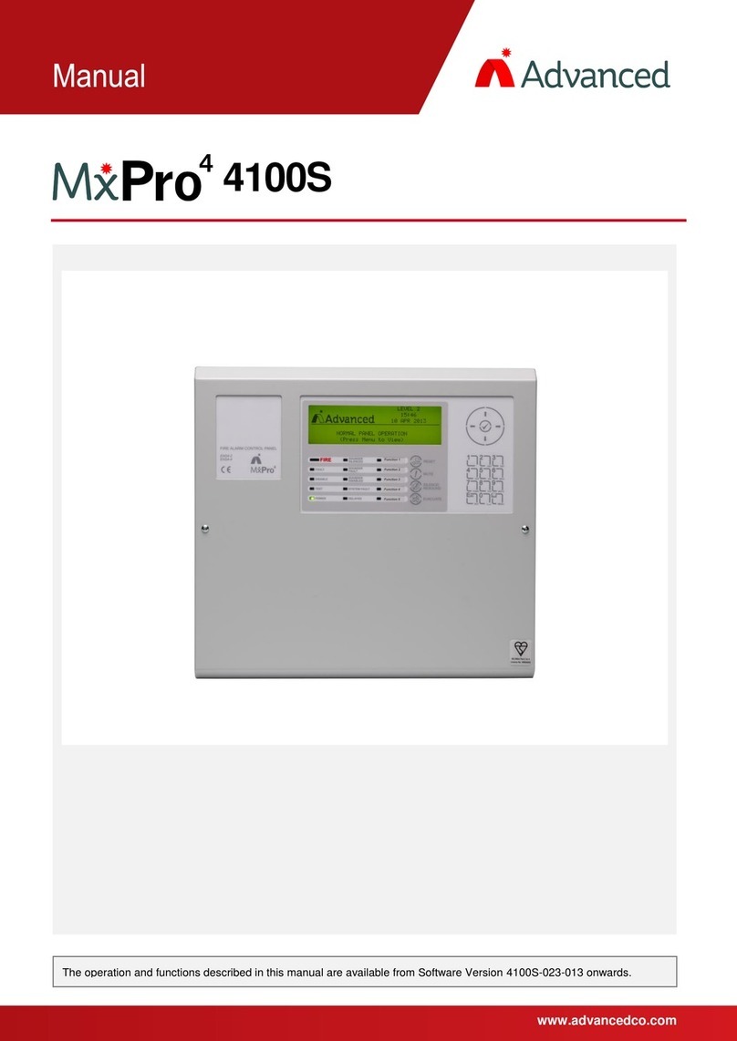
Advanced
Advanced MxPro 4 4100S User manual
Advanced
Advanced MxPro4 Mx-4200 User manual
Advanced
Advanced Quick Zone XL Guide
Advanced
Advanced MxPro4 Series User manual
Advanced
Advanced ExGo Series User manual

