Advanced AS4000 User manual

AS600 - 2018
IRON SLIDER
BEAM ANCHOR
Instruction Manual

INSTRUCTION MANUAL
AS4000 - Iron Slider Beam Anchor
Manual Rev:
AS600R1.3 - 2018
Acopy of this manual must beavailable tousers at all times. Please contact
Advanced Safety for the latest user instruction manual based on date of
manufacture.
UNDER PENALTY OF LAW - IMPORTANT
This manual must be read and understood in its entirety, and used as part of a fall
protection training program, as required by OSHA or any state/local regulatory
agencies. User must read and fully understand the limitations and proper use of the
equipment. All users must be properly trained by their employer prior to use, per
OSHA 29 CFR 1910.66, 29 CFR 1926.503, and applicable local standards.
When used in accordance with instruction specifications, this product meets or
exceeds all applicable OSHA 1926 and ANSI A-10.32-2012 standards for fall
protection. Applicable standards and regulations depend on the application, along
with some state-specific regulations. Consult regulatory agencies for more
information on personal fall arrest systems and associated components.
User Instruction Manuals must always be available to the user of the equipment.
WARNING
Misuseorfailuretofollowwarnings,instructions,andlimitations
ontheuseofthisequipmentmayresultinseriouspersonal
injuryordeath.Forfurtherinstructionsaboutproperuse,refertoasupervisor
orcontact Advanced Safety Solutions, Inc at 1-844-657-1750.

WARNING
•
Use 900 Maximum Average Arrest force (MAAF) ANSI certified energy absorber
lanyard or Leading Edge Self-Retracting Lanyard (SRL-LE). For applications where
anchor point is below the D-Ring connection only use
appropriately rated energy
absorbing lanyards or self-retracting devices.
If you are unsure of compatibility,
please contact manufacturer prior to use of
any fall arrest or restraint equipment.
•
Employees shall be trained in accordance with the requirements of OSHA 29 CFR
1910.66: safe use of the system and its components.
•
Inspect all PFAS equipment prior to each use. Remove defective
equipment immediately.
•
Thoroughly evaluate and plan all elements of PFAS before using it. Calcu- late fall
clearance and swing fall clearance. When calculating distance, be
sure to consider:
•
Deceleration Distance
•
Movement of Harness Attachment (D-Ring)
•
Free-Fall Distance
•
Worker Height
•
Anchorage Connector Elevation
•
Length of Connecting Subsystems
•
Length of D-Ring Connector
•
Length of Full Body Harness Stretch
Do not alter or intentionally misuse this equipment.
COMPATIBILITY LIMITATIONS
Anchorage connector must only be coupled to compatible connectors. OSHA 29 CFR 1926.502 prohibits
snaphooks from being engaged to certain objects unless two requirements are met: it must be a locking type
snaphook, and it must be“designed for” making such a connection. “Designed for” means that the
manufacturer of the snaphook speci
fi
cally designed the snaphook to be used to connect to the equipment
listed. The following connections must be avoided, because they can result in rollout* when a nonlocking
snaphook is used:
•
Direct connection of a snaphook to horizontal lifeline.
•
Two (or more) snaphooks connected to one D-ring.
•
Two snaphooks connected to each other.
•
A snaphook connected back on its integral lanyard.
•
A snaphook connected to a webbing loop or webbing lanyard.
•
Improper dimensions of the D-ring, rebar, or other connection point in relation to the snaphook
dimensions that would allow the snaphook keeper to be depressed by a turning motion of
the snaphook.
*Rollout: A process by which a snaphook or carabiner unintentionally disengages from another
connector or object to which it is coupled. (ANSI Z359.1-2007)
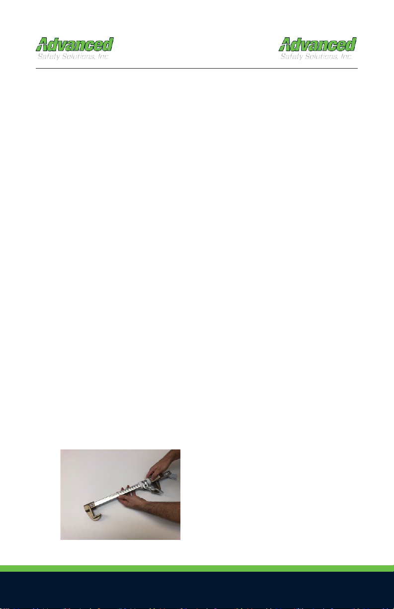
Installation:
1.
Locate a structural steel beam flange capable of withstanding a 5,000-lbf. static load or meeting OSHA
1926.502 requirements for a safety factor of two.
2.
Push in on the latch handle to allow the adjustable hook to move. (fig:1-A)
3.
Keeping the unit perpendicular to the beam, fit the hooks over the edges of the beam flange.
4.
Slide the adjustable hook so that both hooks are snug against the beam flange.
5.
Pull back the adjustable hook to ensure the ratchet teeth are fully seated in the nearest ratchet
notches.
6.
Tug, rock, and twist the anchor in all directions to ensure that it cannot come off of the flange.
*Always re-adjust according to steps 1-6, above when moving to a new or different size beam.
Placement at or below a user’s working height requires integration of a compatible ANSI 359.1 shock-
absorbing lanyard that does not allow the user to extend more than 6 feet (in any direction) from the anchorage
connector before the shock absorber is activated. The beam anchor must be attached to the I-beam flange facing
the user (top flange if worker is above, bottom flange if worker below or underneath the flange, etc.).
fig: 1-A
Beam Flange Width Range: 3.5”-14”
Beam Flange Thickness: .25“ to 1.25”
PERFORMANCE:
Static Tensile Strength: 5000-lbf (22kN)
Maximum Capacity: one worker with max
weight of 310-lbs when used as a single
point anchorage connector for personal fall
arrest or restraint system.
Inspection:
Official periodic inspection must be made at least annually. The inspection must be performed by
a qualified person other than the intended user. If severe weather or conditions exist then
inspections must be carried out more frequently. All inspection results must be logged in the space
provided above. (It is recommended that the anchor device is marked with the date of the next or
last inspection.)
1.
Make sure all labeling is affixed to the unit.
2.
Inspect anchoring system for signs of damage or wear.
3.
Make sure the ring is free to swivel and pivot.
4.
Check for excessive play and wear on the retaining bushing
(Bushing should not wiggle or rotate.)
5.
Insure latches engage and disengageproperly.
6.
Record inspection results in the space provide above.
*If any damage that could affect the strength or operation of the device, or unsafe conditions are
found, proper disposal is required. The anchorage connector must be rendered unusable and
then properly discarded.
fig 2-A
Make sure tags are attached
and legible with original
markings.
Make sure rivets are void of
cracks and are fully seated,
flush with end piece.
Make sure Iron Slider bar is
free from burs and
deformation that would
impede the Iron Sliders
movement.
Compliance:OSHA 1926.502 & 1910.66 / ANSI Z359.1, ANSI Z359.7
CE 0321 / EN 795:1996 (+A1:2000) Class B
Stainless Steel, Aluminum, Zinc Plated Steel, Bronze
WARNING!!!
ALL PERSONS USING THIS EQUIPMENT MUST READ AND UNDERSTAND ALL
INSTR UCTI ONS.
FAI LUR E TODOSOMAY RESU LTI N SER IOUS INJ URY OR DEAT H. USERS SHOULD BE FAMI LIAR
WITH PERTINENT REGULATIONS GOVERNING THIS EQUIPMENT. ALL INDIVIDUALS WHO USE
Max Capacity 310-lbs
DO NOT REMOVE

•
There must be sufficient clearance below the anchorage connector to arrest a fall
before the user strikes the ground or an obstruction. When calculating fall clearance,
account for or a Minimum three-foot safety factor, deceleration distance, user height,
length of lanyard/SRL, and all other applicable factors.
•
This equipment is designed to be used in temperatures ranging from
-40°F to +130°F(-40°C - +54°C).
•
Do not expose this equipment to chemicals or harsh solutions that may
have a
harful effect.
•
All synthetic material must be protected from slag, hot sparks, open flames, or other
heat sources. The use of heat resistant materials is recommended in these
applications.
•
Allowable worker weight limit (including all tools and equipment) is 130–
310 pounds unless otherwise stated on the label or instructions.
Components and Specifications
Rating: 5,000 lb. static load (minimum
breaking strength).
Materials:
High Strength Bar: Aluminum.
Clamp (Adjustable Versi-Clamp and Fixed
End):
Bronze manganese, or
zinc-plated steel.
D-ring: Zinc-plated steel. Internal
Springs: Stainless steel.
.Meets all ANSI and OSHA standards
Fixed
End Clamp
Nylon
Rollers
High Strength
Aluminum Bar
Sliding D-ring with
Impact Indicator
Adjustable
Versi-Clamp
Labels

CONNECTOR COMPATIBILITY LIMITATIONS
Advanced Safety’s equipment must be combined only to compatible connectors that are
suitable to your application. Ensure all connections are compatible in size, shape and
strength. Ensure all connectors are fully closed and locked. OSHA 29 CFR 1926.502
prohibits the use of snap hooks to engage and attach to objects unless the following
requirements are met:
•
Snap hook must be a locking type snap hook.
•
Snap hook must be explicitly designed for such a connection. “Designed for” means
that the manufacturer of the snap hook specifically created the snap hook to be used
to connect to the equipment in question and for personal fall protection equipment.
Use of a non-locking snap hook can result in rollout (a process by which a snap hook or
carabiner unintentionally disengages from another connector or object to which it is
coupled. ANSI Z359.0- 2007). Advanced Safety’s connectors (snap
hooks and carabiners) are designed to be used only as specified in each product’s user’s
instructions.
Avoid the following types of connections:
•
Connection of two (or more) snap hooks or carabiners to one D-ring.
•
Connection of a snap hook back to its integral lanyard or tied into itself unless
otherwise specifically designed.
•
Direct connection of a snap hook to horizontal lifeline. Connect only to O-rings supplied
by manufacturer.
•
Connection in a manner that results in a load on the gate. NOTE: Large throat opening
snap hooks should not be connected to standardsize
•
D-rings or similar objects, as such use will result in a load on the gate if the hook or
D-ring twists or rotates. Large throat snap hooks are designed for use on structural
elements such as rebar or cross members that are not shaped in such a way that they
may capture the gate of the hook.
•
Connection to snap hooks or carabiners. Two snap hooks or carabiners locked to
one another.
•
Direct connection to webbing lanyard, webbing loop, rope lanyard or tie-back (unless
the manufacturer’s instructions for both the lanyard and connector specifically allow
such a connection).

•
Connection of a snap hook to a D-ring, rebar, or other connection point of improper
dimensions in relation to the snap hook dimensions or configurations that could cause
the snap hook keeper to be depressed by a turning motion of the snap hook, or such
that snap hook or carabiner will not fully close and lock, or that roll-out could occur.
Illustration 2 depicts examples of inappropriate connections:
Illustration 2: Inappropriate Connections

Swing Falls:
Minimize swing fall by working as directly below the anchorage point as possible. Worker
movement should remain within 30 degrees maximum deflection of the lifeline from the
vertical line directly below the anchorage point.
Do not permit a swing fall if injury could occur.
Sharp Edges:
Avoid working where sharp edges may contact the lifeline. Provide sufficient protective
padding if avoiding sharp edges is notpossible.
Corrosive Environment:
Extensive exposure to environments where corrosion may occur will damage metal parts in
the Self-Retracting Lifeline. Use caution when working around corrosive compounds such
as ammonia, sewage, fertilizers, sea water or other corrosives.
Chemical Hazard, High Heat and Severe Cold:
Use extreme caution in environments containing acid or caustic chemicals, particularly at
elevated temperatures, as chemical damage that can impair the functionality of the PFAS is
difficult to detect. Do not use the Multi-Direction Anchor Plate in high-heat environments. Hot
sparks and slag can damage the equipment and impair functionality.

Electrical Hazards:
Use extreme caution to avoid contact with high voltage power lines. Both web and wire
cable model Self-Retracting Lifelines may conduct electricity. Moisture absorbed by the
lifeline can provide a path for electrical current to flow, resulting in potential electrical shock.
Locking Speed:
Use extreme caution when working on low-pitched roofs where a worker may slide, rather
than fall.
Fall Clearance:
Consider the following when calculating fall clearance. Clearance required is dependent
on the following factors:
•
Elevation of Anchorage
•
Connecting Subsystem Length
•
Deceleration Distance
•
Free Fall Distance
•
Worker Height
•
D-ring / connector length
•
Movement of Harness Attachment Element
•
Length of Full Body Harness (FBH) Stretch
•
Working Level

Fall Clearance Considerations
A.
Connecting Subsystem(sEnergy Absorbing Lanyard
shown) Length + Movement of Harness Attachment
+ Length of FBH Stretch
B.
Working Level (thickness)
C.
Worker Height + Connector Length
D.
Free Fall - 6 ft. Max. (per ANSI Z359.1)
E.
Deceleration Distance
F.
Total Fall Distance: Sum of A through E
G.
Lower Level or Obstruction
6 ft. Free Fall Lanyard Example
If there is a risk of a fall or if the only anchorage point is below the attachment points on the
harness, it is essential to use a lanyard provided with an energy absorber.
Before using a shock absorbing lanyard, ensure that there is sufficient fall clearance below the
user to prevent any collision with the structure or the ground. If you are
tying off at your feet
with the AS600 Iron Slider, you must factor in a total clearance of up
to 21.5ft. from where you are
tied off at with the AS600.

Note: Owner is to have a written rescue plan and the means to implement it. System is to
be used for fall protection only. Any other use voids the warranty and renders the system
unusable. Always perform a hazard analysis before use that will identify impact and swing
hazards, or any other hazards that may exist. Address and correct all hazards before use.
Always use the buddy system when using fall protection (the monitor or “buddy” does not
need to be physically on the system, just nearby, supervising).
Never add additional carabiners, D-Rings, shackles, or connecting hardware to this system. If
connecting hardware must be added, compatibility must be verified by a competent person.
CLEANING AND MAINTENANCE
Cleaning after use is important for maintaining the safety and longevity of the Multi-
Directional Anchor Plate. Remove all dirt, corrosives, and contaminants from the Iron Slider
AS600 before and after each use. If the AS600 cannot be cleaned with plain water, use mild
soap and water, then rinse and wipedry.
NEVER clean the Iron Slider AS600 with corrosive substances. When not in use, store the
equipment where it will not be affected by heat, light, excessive moisture, chemicals, or other
degrading elements.

INSPECTION LOG
Date of Manufacture:
Model Name/#:
Serial:
Date of First Use:
Inspection Date
Items Noted
Corrective Action
Approved By

WARRANTY
THE FOLLOWING IS MADE IN LIEU OF ALL WARRANTIES OR CONDITIONS, EXPRESS OR
IMPLIED, INCLUDING THE IMPLIED WARRANTIES OR CONDITIONS OF
MERCHANTABILITY OR FITNESS FOR A
PARTICULAR PURPOSE.
Equipment offered by Advanced Safety is warranted against factory defects in workmanship
and materials for a period of one year from date of installation or first use by the original
owner. LIMITED REMEDY: Upon notice in writing, Advanced Safety will repair or replace all
defective items at Advanced Safety’s sole discretion. Advanced Safety reserves the right to
require that the defective item be returned to its plant for inspection before determining the
appropriate course of action.
Warranty does not cover equipment damage resulting from wear, abuse, damage in transit,
failure to maintain the product or other damage beyond the control of Advanced Safety.
Advanced Safety shall be the sole judge of product condition and warranty options. This
warranty applies only to original purchaser and is the only warranty applicable to this
product. Please contact Advanced Safety customer service department for assistance.
LIMITATION OF LIABILITY: IN NO EVENT WILL ADVANCED SAFETY BE LIABLE FOR ANY
INDIRECT, INCIDENTAL, SPECIAL OR CONSEQUENTIAL DAMAGES INCLUDING, BUT
NOT LIMITED TO LOSS OF PROFITS, IN ANY WAY RELATED TO THE PRODUCTS
REGARDLESS OF THE LEGAL THEORY ASSERTED.

Table of contents
Other Advanced Safety Equipment manuals


