Advanced Lifeline 50-2 Operator's manual

User Instruction Manual
Vertical Lifelines
This manual isintended tomeet the Manufacturer’s
Instructions as required byANSI Z359.1
CSA Z259.2.1 andshould beused as part ofan employee
training program as required by OSHA.
WARNING: This product is part of a personal fall arrest or
restraint system. The user must follow the
manufacturer’s instructions for each component ofthe
system. These instructions must be provided to the user of
this equipment. The user must read and understand these
instructions before using this equipment.
Manufacturer’s instructions must be followed forproper use
and maintenance ofthis equipment. Alterations ormisuse of
this equipment, orfailure tofollow instructions, may result in
serious injury or death.
WARNING: Record the product identification information
from the ID label in the inspection and maintenance log in
Section 10 of this manual.
DESCRIPTIONS
Advanced Safety Solutions Inc. Vertical Lifelines are available
invarious styles and configurations.
Following are descriptions oftypical lifelines and lifeline
subsystems. Your model may not be described exactly as
configured.
Vertical Lifeline Assemblies:
50-2: 5/8 inch polyester/polypropylene rope, snap hook at
each end, 50feet long
Advanced Safety Solutions Inc. / Avella, PA/844-657-1750

Advanced Safety Solutions Inc. / Avella, PA / 844-657-1750
75-2: 5/8 inch polyester/polypropylene rope, snap hook at
each end, 75 feet long
100-2: 5/8 inch polyester/polypropylene rope, snap hook at
each end, 100 feet long
Rope Materials:
5/8 inch diameter, polyester/polypropylene rope
Applications
Purpose: Vertical lifelines are intended to be used as part of
a personal fall arrest or restraint system. These lifelines are
not designed for use in horizontal lifeline systems.
Applications include: Inspection work, construction,
demolition, maintenance, oil production, confined space
rescue, window washing.
A.FALL ARREST: The lifeline or lifeline subsystem is used as
part of a complete fall arrest system, which
typically includes a lifeline, rope grab, lanyard, and full body
harness. Maximum permissible free fall is 6 ft. (1.8 m).
B.RESTRAINT: The lifeline or lifeline subsystem is used as
part of a restraint system. Restraint systems typically include
a full body harness and a lanyard to prevent the user from
reaching a fall hazard (leading edge roof work). No vertical
free fall permitted.

Advanced Safety Solutions Inc. / Avella, PA / 844-657-1750
LIMITATIONS: Consider the following application limitations
before using this equipment:
A.CAPACITY: This equipment is designed for use by persons
with a combined weight (person, clothing, tools, etc.) of no
more than 310 lbs. (141 kg). No more than one person may
be connected to a single lifeline.
B.FREE FALL: Personal fall arrest systems used with these
lifelines must be rigged to limit the free fall to 6 ft. (1.8 M)
(according to ANSI Z359.1). Restraint systems must be rigged
such that there is no possible vertical free fall.
C.FALL CLEARANCE: Ensure that adequate clearance exists in
your fall path to prevent
striking an object. The amount of clearance required is
dependent on the type of connecting

subsystem (rope grab, lanyard), the anchorage location, and
the amount ofstretch in the
lifeline. See subsystem manufacturer’s instructions formore
information.
D. ENVIRONMENTAL HAZARDS: Use of this equipment in
areas where environmental hazards
exist may require additional precautions toreduce the
possibility of injury to the user or
damage tothe equipment. Hazards may include, but are not
limited to; high heat, caustic
chemicals, corrosive environments, high voltage power lines,
explosive ortoxic gases, moving machinery, orsharp edges.
F. TRAINING: This equipment is intended to be used by
persons trained in itscorrect
application and use.
APPLICABLE STANDARDS: Refer to national Standards
including ANSI Z359 (.0, .1, .2, .3, and .4) family ofstandards
on fall protection, ANSI Z359.15, ANSI A10.32, CSA Z259.2.1,
and applicable local, state and federal (OSHA) requirements
governing occupational safety for more information about
work positioning systems.
SYSTEM REQUIREMENTS
COMPATIBILITY OF COMPONENTS: Advanced Safety
Solutions Inc. equipment isdesigned for usewith a number of
approved components. Substitutions orreplacements made
with non-approved components may jeopardize compatibility
of equipment and mayaffect the safety and reliability of the
complete system.
IMPORTANT: The type oflifeline used is dependent upon the
application and compatibility requirements ofother system
Advanced Safety Solutions Inc. / Avella, PA/844-657-1750

Advanced Safety Solutions Inc. / Avella, PA / 844-657-1750
components. Contact Advanced Safety if you have any
questions about compatibility.
COMPATIBILITY OF CONNECTORS: Connectors are
considered to be compatible with
connecting elements when they have been designed to work
together in such a way that their sizes and shapes do not
cause their gate mechanisms to inadvertently open
regardless of how they become oriented. Contact Advanced
Safety if you have any questions about compatibility.
Connectors (hooks, carabiners, and D-rings) must be capable
of supporting at least 5,000 lbs. (22kN). Connectors must be
compatible with the anchorage orother system components.
Do notuseequipment that is not compatible. Non-
compatible connectors may unintentionally disengage.
Connectors must be compatible in size, shape, and strength.
Self-locking snap
hooks and carabiners are required by ANSI Z359.1 and OSHA.
MAKING CONNECTIONS: Only use self-locking snap hooks
and carabiners with this equipment. Only use connectors
that are suitable toeach application. Ensure all connections
are compatible in size, shape and strength. Donotuse
equipment that isnot compatible. Ensure all connectors are
fully closed and locked.
Advanced Safety connectors (snap hooks andcarabiners) are
designed to be used only as specified ineach product’s user’s
instructions. Advanced Safety snap hooks andcarabiners
should not be connected:
A.To a D-ring to which another connector is attached.
B. In a manner that would result in a load on the gate.
NOTE: Large throat opening snap hooks should not be
connected to standard size D-rings or similar objects which
will result in a load on the gate if the hook or D-ring twists or

Advanced Safety Solutions Inc. / Avella, PA / 844-657-1750
rotates. Large throat snap hooks are designed for use on fixed
structural elements such as rebar or cross members that are
not shaped in a way that can capture the gate of the hook.
C. In a false engagement, where features that protrude from
thesnap hook or carabiner catch on the anchor and without
visual confirmation seems to be fully engaged to the anchor
point.
D. To each other.
E. Directly to webbing or rope lanyard or tie-back (unless the
manufacturer’s instructions for both the lanyard and
connector specifically allow such a connection).
F. To any object which is shaped or dimensioned such that
the snap hook or carabiner will not close and lock, or that
roll-out could occur.
G. In a manner that does not allow the connector to align
properly while under load.
ANCHORAGE STRENGTH: The anchorage strength required is
dependent upon the
application:
A.FALL ARREST: In accordance with ANSI Z359.1, anchorages
selected for fall arrest systems shall have a strength capable
of sustaining static loads applied in the directions permitted
by the system of at least:
• 5,000 pounds (22.2 kN) for non-certified anchorages; or,
• Two times the maximum arresting force for certified
anchorages.
When more than one fall arrest systems is attached to an
anchorage, the applicable strength requirement should be
modified by the number of systems attached to the
anchorage. Per OSHA 1926.500 and 1910.66: Anchorages
used for attachment of personal fall arrest systems shall be
independent of any anchorage used to support or suspend

Advanced Safety Solutions Inc. / Avella, PA / 844-657-1750
platforms and capable of supporting at least 5,000 pounds
(22.2 kN) per attached user; or, be designed, installed, and
used as part of a complete PFAS which maintains a safety
factor of at least two and is under the supervision of a
qualified person.
B. RESTRAINT: Anchorages selected for restraint and travel
restraint systems shall have a
strength capable of sustaining static loads applied in the
directions permitted by the system of at least:
•1,000 pounds (4.5 kN) for non-certified anchorages; or,
• Two times the foreseeable force for certified anchorages.
When more than one fall arrest systems is attached to an
anchorage, the applicable strength requirement should be
modified by the number of systems attached to the
anchorage.
OPERATION AND USE
WARNING: Do not alter or intentionally misuse this
equipment. Consult Advanced Safety Solutions Inc. when
using this equipment in combination with components or
subsystems other than those described in this manual. Some
subsystem and component combinations may interfere with
the operation of this equipment. Use caution when using this
equipment around moving machinery, electrical hazards,
chemical hazards, and sharp edges.
WARNING: Consult your doctor if there is reason to doubt
your fitness to safely absorb the shock from a fall arrest. Age
and fitness seriously affect a worker’s ability to withstand
falls. Pregnant women or minors must not use Eagle
Industrial Tools Vertical Lifelines or subsystems.
BEFORE EACH USE of this equipment, carefully inspect it
according to steps listed in section 5.0 of this manual.

Advanced Safety Solutions Inc. / Avella, PA / 844-657-1750
PLAN your fall arrest or restraint system before using this
equipment. Consider all factors that will affect your safety
during use of this equipment. Consider the following points
when planning your system:
A. ANCHORAGE: Select a rigid anchorage point that is capable
of sustaining the loads specified in section 2.3. For fall arrest
applications, select anchorage locations that will minimize
free fall and swing fall hazards. For restraint applications,
locate the anchorages such that no vertical free fall is
possible.
B. FREE FALL: To avoid increased free fall distance, do not
work above the anchorage level. Rig personal fall arrest
systems so that the free fall is limited to 6 ft. (1.8 m) (ANSI
Z359.1). Rig restraint systems such that no vertical free fall is
possible.
C. FALL ARREST FORCES: The personal fall arrest system must
limit fall arrest forces to 1,800 lbs. (8 kN). And deceleration
distance must not exceed 42 in. (1 m). Do not use a body belt
for fall arrest applications.
D. SWING FALLS: Swing falls occur when the anchorage point
is not directly above the point where a fall occurs. The force
of striking an object in a swing fall may cause
serious injury. Minimize swing falls by working as directly
below the anchorage point as possible. Do not permit a swing
fall if injury could occur.
E. FALL CLEARANCE: Ensure sufficient clearance exists in your
fall path to prevent striking
an object during a fall. The clearance required is dependent
upon the subsystem (rope grab
and lanyard, rope grab and carabiner) and lifeline properties.
Synthetic rope is subject to elongation, or stretch. As the
distance between the anchorage and the grab increases, the
portion of the vertical lifeline that is subjected to loads

Advanced Safety Solutions Inc. / Avella, PA / 844-657-1750
increases, thereby increasing the effects of elongation.
Elongation can be as much as ten percent for rope in wet
conditions. Consideration of elongation must be considered
when estimating fall clearance distances. The Table below
shows the approximate elongation for new lifelines in dry
conditions. The elongation specified is for an applied static
load of 900 lbs. (4 kN). Wet ropes generally have more
elongation than dry ropes. Allow for additional elongation in
wet or humid conditions
Lifeline Elongation
Lifeline
Material
25F
t.
50F
t.
75F
t.
100
Ft.
150
Ft.
200
Ft.
250
Ft.
300
Ft.
5/8”Polye
ster
Polypropy
lene
2.5
Ft.
5Ft
.
7.5
Ft.
10Ft
.
15Ft
.
20Ft
.
25Ft
.
30Ft
.
F.SHARP EDGES: Avoid working where your lifeline, lifeline
subsystem, or other system
components will be in contact with, or abrade against,
unprotected sharp edges. Do not loop
a lifeline around small diameter structural members. If
working with this equipment around
sharp edges is unavoidable, provide protection by using a
heavy pad over the exposed sharp edge.
G.RESCUE: The employer must have a rescue plan and the
ability to implement it.
H.AFTER A FALL: Components which have been subjected to
fall arrest forces must be
removed from service and destroyed.

Advanced Safety Solutions Inc. / Avella, PA / 844-657-1750
I. GENERAL USE CONSIDERATIONS: Avoid working where
your lifeline may cross or tangle
with that of another worker. Do not allow your lifeline to pass
under your arms or between
your feet.r
MAKING CONNECTIONS When using a hook to connect
components or to an anchorage, ensure roll-out cannot
occur. Self-locking snap hooks and carabiners should be used
to reduce the possibility of roll-out. Do not tie a knot in the
lifeline. Do not attach a snap hook directly to a horizontal
lifeline. Follow manufacturer’s instructions for each
component of the system.
All lifelines either have a self-closing and self-locking snap
hook pre-installed in a thimbled eye at the both ends of the
lifeline or for lifelines with snap hook only on the anchorage
end a thimbled eye will be spliced on the non-anchorage end
to prevent the fall arrester from inadvertently traveling off
the end of the lifeline. Attach the self-closing self-locking snap
hook or carabiner to the anchorage. Attach a minimum five-
pound counter weight to the non-anchorage end to maintain
a taut line. Let the non-anchorage end hang freely. If the rope
passes over an edge of any kind, or any type of rough or
uneven surface, provide abrasion protection.
5 –
A. CONNECTING TO AN ANCHORAGE OR ANCHORAGE
CONNECTOR: Lifelines or
Lifeline subsystems supplied with connecting hooks should be
connected to the anchorage
in accordance with section 3.3. Lifelines supplied without
hooks must have a hook or anchorage connector spliced
directly to the lifeline Connectors attached to synthetic rope
lifelines must be attached using a spliced eye termination and
thimble. The splice must be made with 5 tucks. The
connection must support 5,000lbs.

Advanced Safety Solutions Inc. / Avella, PA / 844-657-1750
Fall
IMPORTANT: Knots must notbe used for load bearing end
terminations.See ANSI Z359.1.
Some knots reduce lifeline strength fifty percent ormore.
IMPORTANT: If the user splices orforms end terminations,
proper procedures must be followed to ensure compatibility
in size, shape, and strength. Advanced Safety Solutions Inc.
is notresponsible for subsystems notmanufactured by
Advanced Safety Solutions Inc.
B. CONNECTING ROPE GRAB TO LIFELINE: Follow the rope
grab manufacturer’s instructions
for connecting the rope grab tothe lifeline.

Advanced Safety Solutions Inc. / Avella, PA / 844-657-1750
AFTER USE of this equipment, clean and store according to
section 6.0 of this manual.
TRAINING
4.1 It is the responsibility of the user to assure they are
familiar with these instructions, and are trained in the correct
care and use of this equipment. User must also be aware of
the operating characteristics, application limits, and the
consequences of improper use of this equipment. WARNING:
Training must be conducted without exposing the trainee to a
fall hazard. Training should be repeated on a periodic basis.
INSPECTION
• Before Each Use inspect according to steps listed in section
5.2.
• This Equipment must be inspected according to steps listed
in section 5.2 by a competent
person, other than the user, at least annually. Record the
results of each inspection in
the inspection and maintenance log in Section 10. NOTE:
Cal/OSHA requires personal fall
arrest systems be inspected prior to each use for wear,
damage, and defects and inspected
by a competent person1 at least twice a year, in accordance
with the manufacturer’s
recommendations, with inspection dates documented.
WARNING: If this equipment has been subjected to fall arrest
forces remove from service and destroy.
IMPORTANT: Extreme working conditions (harsh
environments, prolonged use, etc.) may require increasing
the frequency of inspections.

Advanced Safety Solutions Inc. / Avella, PA / 844-657-1750
Step 1. Inspect lifeline hardware (snap hooks, ferrules,
thimbles, etc.). These items must not be damaged, broken or
distorted. These items must be free of sharp edges, burrs,
cracks,
worn parts, or corrosion. Hook gates must move freely and
lock upon closing.
Step 2. Inspect the lifeline per the following:
SYNTHETIC ROPE: Inspect rope for concentrated wear.
Material must be free of frayed
strands, broken yarns, cuts, abrasions, burns, and
discoloration. The rope must be free
of knots, excessive soiling, paint build-up, and rust staining.
Rope splices must be tight,
with five full tucks, and thimbles must be held firmly by the
splice. Check for chemical
or heat damage; indicated by brown, discolored, or brittle
areas. Check for ultraviolet
damage; indicated by discoloration and splinters and slivers
along the rope surface. All
of the above factors are known to reduce rope strength.
Damaged or questionable rope
should be replaced.
Step 3. Inspect labels. All labels must be present and fully
legible.
Step 4. Inspect each system component or subsystem
according to manufacturer’s instructions.
Step 5. Record the inspection date and results in the
inspection log in Section 10.
If inspection reveals an unsafe or defective condition,
remove equipment from service and destroy, or contact an
authorized service center for repair.

MAINTENANCE, SERVICING, STORAGE
Clean the lifeline with water and a mild detergent. Wipe
hardware dry with a clean, dry cloth and hang toair dry. Do
not force dry with heat. An excessive build-up of dirt, paint,
etc. may prevent the lifeline from working properly, and in
severe cases, weaken the rope.
Additional maintenance and servicing procedures must be
completed by and authorized service center. Authorization
must be in writing. Do not disassemble this equipment.
Store the lifeline in a cool, dry, clean environment, out of
direct sunlight. Avoid areas where chemical vapors may be
present. Thoroughly inspect the lifeline after extended
storage.
SPECIFICATIONS
LIFELINE SPECIFICATIONS: The Tensile strength of Advanced
Safety Solutions Inc. 5/8” diameter polyester/polypropylene
blend 3 strand rope is7000 lbs. The melting point is330
degrees Fahrenheit
HARDWARE SPECIFICATIONS: Snap Hook: Drop forged,
Carbon steel self-locking snap hook, 5,000 lbs. (22.2 kN).
Tensile strength.
Advanced Safety Solutions Inc. / Avella, PA/844-657-1750
Advanced Safety Solutions Inc. / Avella, PA / 844-657-1750
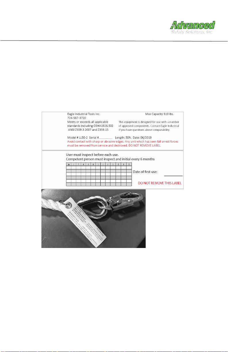
LABELING All Labeling must be present and fully legible.

Advanced Safety Solutions Inc. / Avella, PA / 844-657-1750
Date of Manufacture:
Model #:
Date of First use:
Inspection Date
Inspection
items noted
Corrective action
Maintenance
performed
Approved By:
Approved By:
Approved By:
Approved By:
Approved By:
Approved By:
Approved By:
Approved By:
Approved By:
Approved By:
Approved By:
This manual suits for next models
2
Table of contents
Other Advanced Safety Equipment manuals


