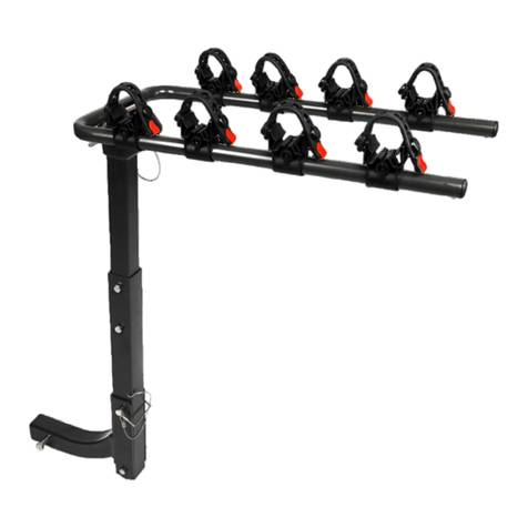
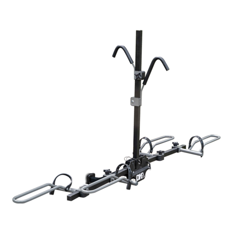
DK2 BCR590 User manual

BCR590
HITCH MOUNTED BIKE CARRIER
2 BICYCLE CAPACITY • HITCH MOUNTED • PLATFORM DESIGN
USER MANUAL
1 (888) 277-6960 | WWW.DETAILK2.COM/BCR590-INFO
DK2 USA WEST
4301 S VALLEY VIEW BLVD.
SUITE 10-11 LAS VEGAS, NEVADA
89103 USA
DK2 USA EAST
3750 SOUTH AVENUE,
NORTH UNIT TOLEDO, OHIO
43615 USA
DK2 CORPORATE HEAD OFFICE
5330 MAINWAY
BURLINGTON, ONTARIO
L7L6A4 CANADA

2 | BCR590 man. v.201209
ENGLISH
Questions, problems, missing parts? DO NOT return to your retailer.
Please call our customer service department at: 1 (888) 277-6960. Our customer service sta are
ready to provide assistance.
If a part is damaged or missing, replacement parts can be shipped from our facility. For immediate
help with assembly, or for additional product information, call our North American toll-free number:
1 (888) 277-6960.
SAVE THIS MANUAL
You will need this manual for safety instructions, operating procedures, and warranty.
Put it and the original sales invoice in a safe, dry place for future reference.
STOP!

BCR590 man. v.201209 | 3
ENGLISH
PARTS LIST ...........................................................................5
SCHEMATICS .........................................................................6
IMPORTANT SAFE OPERATING PRACTICES ..............................................8
GENERAL. . . . . . . . . . . . . . . . . . . . . . . . . . . . . . . . . . . . . . . . . . . . . . . . . . . . . . . . . . . . . . . . . . . . . . . . . . . . . 10
ASSEMBLY ...........................................................................12
USE..................................................................................19
WARRANTY...........................................................................20
TABLE OF CONTENTS

SECTION I
SCHEMATICS & PARTS

BCR590 man. v.201209 | 5
ENGLISH
SCHEMATICS & PARTS
PARTS LIST
No. Description Qty.
1Main bracket 1
2 Main vertical pole 1
3Side pole 2
4Connecting arm 1
Left wheel cradle 2
6Right wheel cradle 2
7Short frame support arm 1
8Long frame support arm 1
9 L-shaped safety pin with lanyard - Φ 9.3mm 3
10 M10x50 hex socket head countersunk screw 1
11 M8 Hex key 1
12 M6 Hex key 1
13 Hitch spacer 1
14 Hitch bolt 1
15 R-clip cotter pin 1
16 Hex socket head bolt 2
17 Spring washer 2
18 M12 Washer 1

6 | BCR590 man. v.201209
ENGLISH
SCHEMATICS & PARTS
SCHEMATICS
2
4
14
13
15
1
10
11
5
6
5
3
612
9
7
8
3
16
18
17

SECTION II
SAFETY

8 | BCR590 man. v.201209
ENGLISH
SAFETY
IMPORTANT SAFE OPERATING PRACTICES
IMPORTANT: Read safety rules and instructions carefully before using this equipment.
Read and follow instructions carefully. Save owner’s manual for future reference
or parts information. Be certain any future user of this carrier is aware of correct
attachment and use.
IMPORTANT WARNING: It is critical that your DK2 Bike Rack is properly secured to
the vehicle.
• Attaching it improperly could result in a vehicular accident, causing serious bodily
harm, injuries, or death to you or to others.
• Securing racks and accessories to your vehicle is your legal responsibility. Check
the rack prior to use, and inspect the components for adjustment, wear, and
damage periodically.
• You must read and understand all of the instructions and cautions before you
install or use the bike rack.
• If you do not understand all of the instructions and cautions, or if your mechanical
experience precludes following them, have the rack installed by a professional.
CAUTION: Safety first - Read this manual carefully before attaching and using your
bike rack. We recommend that you read this manual completely so that you are fully
aware of all important safety recommendations. Record your serial number.
DANGER: This equipment was built to be operated according to the rules for safe
operation in this manual. As with any type of equipment, carelessness or error on the
part of the operator can result in serious injury or property damage.
• To use this equipment properly, you must observe the safety regulations, the assembly
instructions and the operating instructions to be found in this manual.
• All persons who use and service the rack must be informed about potential hazards and
must be well acquainted with this manual.

BCR590 man. v.201209 | 9
ENGLISH
SAFETY
IMPORTANT SAFE OPERATING PRACTICES
WARNING: Though this rack is designed to fasten securely to most 5cm (2”) or 2.5cm
(1”) automotive hitch receivers, variations in vehicle design and specifications make
it impossible to guarantee that it will in all cases. This assumes the vehicle is in good
condition in the area supporting the hitch. You are responsible to ensure the rack
attaches safely and securely to the vehicle and that it holds the bicycles in a safe
manner.
WARNING:
• Do not exceed the rated capacity of this bike carrier.
• Do not load more than 2 bicycles, weighing in total, less than 36kg (80lb).
• Do not carry anything other than bicycles with this carrier.
CAUTION:
• Ensure that the use of this rack is not in contravention of local trac regulations
with regard to protrusion from your vehicle, or the obscuration of license plates or
tail lights resulting from its use.
• Always use the cradles and straps to secure bicycles to the carrier. To increase the
stability and security of the load, you may use rope, shock cord, or cable locks.
• Worn or frayed straps should be placed immediately at the first sign of wear.
Check them frequently.
• This rack is designed for use on passenger cars, trucks, and SUVs that have the correct hitch
receiver and hitch receiver weight capacity.
• Inappropriate use and fastening of the rack to the vehicle may lead to damage to bicycles,
the rack, and/or your vehicle. It my also inflict damage on other vehicles behind and
elsewhere on the road with you.

10 | BCR590 man. v.201209
ENGLISH
SAFETY
IMPORTANT SAFE OPERATING PRACTICES
GENERAL INFORMATION
• We suggest, at the start of every trip, to stop and check bicycles after 150m (500ft.)
• This bike carrier is not recommended to keep bikes secure and safe from damage during the
bumps and vibration of o-road travel. They may shift and become damaged or loose.
• Watch that hot vehicle exhaust is not directed near bicycle tires. They can be damaged by
exhaust heat.
• Be careful that the bicycles are supported at a height to prevent their contacting the ground
while being carried. For this reason particularly, the bike carrier is not designed for use on a
fifth wheel or any type of trailer.
• Do not take the bike carrier through an automatic car wash.
1. READ YOUR OWNER’S MANUAL CAREFULLY.
Get to know your bike rack and familiarize yourself with its applications and limitations.
2. USE THE RACK ACCORDING TO THE GUIDELINES OF THIS MANUAL.
Do not abuse it or force it to do a job for which it was not designed.
3. USE ONLY ORIGINAL EQUIPMENT PARTS AND ACCESSORIES.
Consult this owner’s manual. The use of incorrect accessories may produce unforeseen
hazards.

SECTION III
ASSEMBLY

12 | BCR590 man. v.201209
ENGLISH
ASSEMBLY
Except for the cradle assemblies, this product is shipped from the factory in a disassembled
state.
Make some room at the rear of your vehicle. Although once assembled, the bike rack is easy
to slip into your hitch receiver. For simplicity, the initial assembly is best done directly onto the
back of the vehicle.
Remove everything from the carton and check the components against the parts list,
familiarizing yourself with them as you go. Do this in a cleared space near the rear of your
vehicle. Retain packing materials until you are sure everything is present and in good condition.
Unpack the contents of your bike carrier and lay the parts out on the flat surface.
Unfold the two outer arms of the tray rack and install the black safety pins through each of the
three holes on the main bracket. (fig. 1)
FIG.1
12
3
STEP1:
STEP2:

BCR590 man. v.201209 | 13
ENGLISH
ASSEMBLY
STEP3:
Insert hitch tongue into rack base. (fig. 2), then install the two hex head mounting bolts into the
bottom of the rack base and fully tighten. (fig. 3)
FIG.2
FIG.3
STEP4:
Slide the wheel trays onto the beam making sure to alternate one pair to the left and one pair to
the right of each other to allow for adjustment for individual bike wheel bases. (fig. 4)
FIG.4

14 | BCR590 man. v.201209
ENGLISH
ASSEMBLY
STEP5:
This rack comes ready to install into a 2” hitch receiver.
1. For 1” hitch receivers, use the supplied hex wrench to unscrew the fixing bolt. (fig. 5)
FIG.5
2. Remove the spacer. (fig. 6)
FIG.6

BCR590 man. v.201209 | 15
ENGLISH
ASSEMBLY
STEP6:
1. Install the rack onto the vehicle by sliding the tongue (t, fig. 7) into the hitch receiver.
2. Insert hitch bolt (b, fig.7) and tongue and tighten securely (fig. 7).
3. Insert lock pin (L, fig. 8) through hole on the other side of the hitch bolt. (b, fig. 8)
FIG.7
b
t
s
r
FIG.7
t
s
rb
L
FIG.8
FIG.8

16 | BCR590 man. v.201209
ENGLISH
ASSEMBLY
STEP7:
Locate the two frame support arms. (fig. 9) These arms slide down the central upright beam of
the tray rack and by tightening the lock knobs, secure the frame of the bicycle to the rack (fig.
10). Notice that one arm is longer than the other. This allows you to accommodate dierent sizes
and styles of frames. To raise the arms up and away from the frame or remove them from the
central beam, loosen the lock knob on the side of the arm bracket to release the arm from the
central beam.
FIG.9
FIG.10

BCR590 man. v.201209 | 17
ENGLISH
ASSEMBLY
STEP8:
Adjust the wheel tray locations to match the wheelbase of your bikes.
• Be sure to tighten the lock knobs on each wheel tray to prevent them from moving out of
place or vibrating o while driving.
• Load the bikes onto the rack with the handlebars facing in opposite directions from each
other to avoid interference between the bikes.
• Lower the frame support arms onto the frame of each bike so that the bike is secure on the
rack.
• Use the rubber straps on each wheel tray to secure each bike wheel to the tray.

SECTION IV
USE & WARRANTY

BCR590 man. v.201209 | 19
ENGLISH
USE
NOTE: Before each use, be sure all the components of the rack are in good working order.
Verify that all hardware is tight and secure before mounting bicycles onto the BCR590.
NOTE:
• Generally, bicycles should be mounted with the heavier closest to the vehicle, working
out to the lighter bicycle.
• It is usually easiest to alternate the direction that the bicycles face, preventing the
handlebars from interfering with each other.
1. Check that all the bicycles are fastened securely and that they are stable.
2. Check the clearance. It is the responsibility of the driver to ensure there is sucient
clearance. This is dependent on the vehicle, the load, and the road. Clearance should allow
for the distance away from the rear wheels and the movements imposed by driveway ramps
and speed bumps. It should be between 30cm and 38cm (12” and 15”).

20 | BCR590 man. v.201209
ENGLISH
WARRANTY
LIMITED ONE (1) YEAR WARRANTY
WHAT IS COVERED
Detail K2 INC. warrants to the original purchaser of a Detail K2 item that the product will be warrantied for a period
of one (1) year from the date of the original purchase.
If within one (1) year from the original date of purchase this product fails due to defect in material or workmanship,
Detail K2 will repair, replace, or supply any defective part at our option. Upon expiry of one (1) year, Detail K2 will
have no further liability related to the product.
Detail K2 does not authorize any party, including its authorized distributors or dealers, to oer any other warranty
on behalf of Detail K2 Inc.
THIS WARRANTY DOES NOT COVER OR APPLY TO:
a) Damage to the product due to misuse, mishandling and abuse
b) Improper installation, maintenance and storage
c) Expendable parts such as nuts and bolts, pins and springs
d) Normal wear and tear
e) Consequential damage and incidental damages such as damage to persons or property
This Detail K2 product is intended for personal use only. It is not intended for commercial use and subsequent use
in this capacity will void all warranty claims.
PROCEDURE FOR OBTAINING A RETURN AUTHORIZATION
Within the one (1) year warranty period, the purchaser of the product must notify an authorized distributor or dealer
of the claimed defect and provide proof of original purchase. At this time the validity of the claim will be determined
and a Return Goods Authorization Number (RGA) will be issued if approved. No returned product will be accepted
under warranty unless accompanied by an RGA# issued by Detail K2 Inc.
RESOLUTION FOR A DEFECTIVE PRODUCT
Detail K2 Inc. will at its option repair or replace the defective product covered by this warranty. The repaired
product will be shipped to the purchaser upon completion. All transportation charges shall be the responsibility of
the purchaser. Any damage in transit will be the responsibility of the carrier or at the risk of the purchaser.
Other manuals for BCR590
1
Table of contents
Languages:
Other DK2 Automobile Accessories manuals