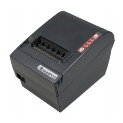
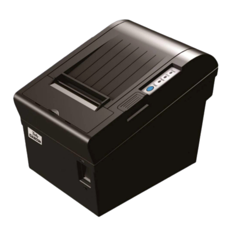
AdvanPOS WP-T800 User manual

1 Station Thermal Line
Receipt Printer
MODEL :
WP-T800
VERSION
: 1.00

WP-T800 1 Station Thermal Line Printer
CONTENTS
1. GENERAL DESCRIPTION..............................................................................3
1.1 OVERVIEW................................................................................................... 3
1.2 FEATURES ................................................................................................... 3
1.3 ACCESSORIES.............................................................................................. 3
2. MAIN SPECIFICATIONS.................................................................................4
3. EXTERNAL APPEARANCE AND PART DESCRIPTIONS............................5
4. INSTALLATIONS.............................................................................................6
4.1 HOW TO CONNECT POWER ADAPTER............................................................ 6
4.2 HOW TO CONNECT CASH DRAWER ............................................................... 6
4.2 SETTING OF THE PRINTER COVER AND SETTING PAPER ................................. 7
5. CONTROL PANEL ..........................................................................................8
5-1. BASIC OPERATION ...................................................................................... 8
5-2. SWITCH OPERATION (COMBINED SWITCH OPERATION).................................. 9
5-3. SETTING................................................................................................... 11
5-3-1. BAUD RATE............................................................................................11
5-3-2. SELECT HANDSHAKING BUSY CONDITION......................................11
5-3-3. SELECT PRINTING SPEED................................................................... 11
5-3-1. SELECT PRINT DENSITY...................................................................... 11
6. INTERFACE SPECIFICATIONS ...................................................................12
6.1 CHANGING THE INTERFACE CARD ................................................................ 12
6.2 SERIAL INTERFACE SPECIFICATIONS ............................................................ 12
6.3 PARALLEL INTERFACE SPECIFICATIONS ........................................................ 13
7. DRAWER KICK CONNECTOR.....................................................................15
7.1 SPECIFICATIONS ........................................................................................ 15
7.2 CONNECTOR
’
S PIN CONNECTION ................................................................ 15
8. CONTROL CODE..........................................................................................16
8.1 ATTACHED COMMAND DESCRIPTION ........................................................... 16
8.2 CONTROL CODES ...................................................................................... 17
9. CHARACTER CODE TABLES......................................................................26
9.1 INTERNATIONAL CHARACTER SETS .............................................................. 26
9.2 CODE PAGE: 00H TO 7FH.......................................................................... 27
9.3 CODE PAGE: PC437 (USA, EUROPEAN STANDARD) ................................... 28
- 1 -

WP-T800 1 Station Thermal Line Printer
9.4 CODE PAGE: KATAKANA (JAPANESE)........................................................... 29
9.5 CODE PAGE: PC850 (MULTILINGUAL)......................................................... 30
9.6 CODE PAGE: PC860 (PORTUGUESE).......................................................... 31
9.7 CODE PAGE: PC863 (CANADIAN-FRENCH) ................................................. 32
9.8 CODE PAGE: PC865 (NORDIC) .................................................................. 33
9.9 CODE PAGE: PC852 (EASTERN EUROPE)................................................... 34
9.10 CODE PAGE: PC866 (RUSSIAN)............................................................... 35
9.11 CODE PAGE: PC857 (TURKISH) ............................................................... 36
9.12 WINDOWS CODE PAGE............................................................................. 37
10. EXTERNAL DIMENSIONS..........................................................................38
- 2 -

WP-T800 1 Station Thermal Line Printer
1. GENERAL DESCRIPTION
1.1 Overview
The WP-T800 Series Line Thermal Receipt Printer is designed for use with
ECR, electronic instruments, computer peripheral equipment, kitchen
printers and so on.
1.2 Features
1). Compact desktop Line Thermal printer.
2). Easy loading designed for dropping the paper roll
3.). Interface conformity to RS-232C, centronics ,USB port depends on the
Interface card which is removeable and other option of Interface for
different application.
4). Command protocol is compatible with ESC/POS.
5). 2 drawer kick-out.
6). The resident data buffer has storage capacity of about 128K-bytes,
enable data to be received even while printing.
7). Support download bit image, directly bit image and bar-code printing.
8). The sensors include paper end, paper near end and cover sensor.
1.3 Accessories
The following parts are included in this set of printer. Please confirm.
Paper roll (1 roll)
Power adapter (1 unit)
Power core (1 unit)
User
痴
ma nual (1 booklet)
Option( one of items below will be included)
Cable for RS-232C (depend on RS-232C interface card) (1 unit)
Cable for Centronics (depend on Centronics interface card) (1 unit)
Cable for USB (depend on USB interface card) (1 unit)
- 3 -

WP-T800 1 Station Thermal Line Printer
2. MAIN SPECIFICATIONS
Item Description
1 Printing method Thermal line
2 Printing speed Approx. 150~220mm / second
3 Number of columns 40 columns
4 Character structure 12x24 (alphanumeric)
5 Line pitch 1/6 inch (4.23mm)
6 Detector Paper end,Paper near end, cover
7 Paper Single-ply thermal paper roll
Paper roll 79.5 ±0.5 (W) x 83 (max) mm
8 Reliability 100KM
9 Power supply 24VDC / 2.1A .
10 Interface RS-232C, Centronics and USB
11 Weight Approx.1.25Kg
12 External dimensions 140.7(W) x 190(D) x 133(H)mm
13 Operating temp. 0 to 40℃
14 Storage temp. -20 to 60℃
15 SRAM 128 KB
16 FLASH 512 KB
- 4 -

WP-T800 1 Station Thermal Line Printer
3. EXTERNAL APPEARANCE AND PART DESCRIPTIONS
1)
1Printer cover
2Cover open lever
3Cutter cover
4Power switch
5Control panel
6DIP switch cover
7Interface connector
8Power connector
9Cash Drawer connector
- 5 -

WP-T800 1 Station Thermal Line Printer
4. INSTALLATIONS
4.1 How to Connect Power Adapter
(1) Ensure that the power switch is
OFF.
(2) Plug the power connector into the
printer
痴
powe r connector at the
arrow mark facing upward.
(3) Plug the power cord into the outlet,
and turn on the power.
(4) Connector Specifications shows as
below:
Pin Number Signal Name
1 +24VDC
2 GND
3 NC
Shell Frame GND
4.2 How to Connect Cash Drawer
(1) Ensure that the power switch is OFF.
(2) Plug the cash drawer connector into the
Drawer kick out connector at the arrow
mark facing upward.
(3) Plug the connector into the RJ11 phone
jack.
Note: Power for drawer kick out is 24vdc, if
voltage of cash drawer is different, it may
cause cannot open situation or harm the cash
drawer.
- 6 -

WP-T800 1 Station Thermal Line Printer
4.2 Setting of the Printer Cover and Setting Paper
(1) Push the cover open lever, and open
the printer cover
(2) Remove any used paper roll’s core,
and insert the paper roll as picture
bellows shown:
Put the paper roll into paper trough and pull
(3) Pull out the leading edge of paper ,
No
paper thickness are 0.06-0.10mm
out the leading edge of the paper as picture
above shown.
m
close the printer cover
te :
1.
2.paper width are range from 79-80m
3.Roll diameter max. 83mm
- 7 -

WP-T800 1 Station Thermal Line Printer
WP-T800 1 Station Thermal Line Printer
- 8 -
5. CONTROL PANEL
5-1. Basic Operation
1. Feed Line feed button
When this push-button switch is pressed once briefly (for
0.5 seconds or less), the paper is fed forward by one line.
When it is held down continuously, the paper is fed
forward continuously until the switch is released.
2. Repeat Repeat button
When on page mode or line mode situation, there maybe
paper jam or paper exhaust situation , please press
repeat button, then printer will repeat the last event which
was not complete.
3. Power lamp (green LED)
Lights indicate power well.
4. Paper lamp (Yellow LED)
•Lamp indicator will remain lighting when paper near
end.
•Lamp indicator will keep sparkling when paper end, and need to
replace a new one.
The flash timing chart shows as below:
Printer status Blinking Pattern
Paper end
ON
OFF
500 ms
ON
OFF
Paper near end
Table 5-1. SEL Lamp Display
5. Error lamp (red LED)
When printer cover is not properly closed or paper jam happen on
cutter part or paper is not put properly , the erroe indicator lamp(red
LED) will light.
- 8 -

WP-T800 1 Station Thermal Line Printer
5-2. Switch Operation (Combined Switch operation)
T1. SELF PRINT TES
LF + POWER ON (Turn
t
h
he power on while
olding the LF button
epressed, the buzzerd
gives one short beep.)
p
t
s
e hen
the LF button is held
Self-testing will be
erformed according to
he VER. NO., printer
ettings and characters
tc (Ref. sheet1). W
again after self-printing
stopped, the printer will
p
is mode, it is necessary
rint out again. To turn off
th
to turn off the printer
power completely.
- 9 -

WP-T800 1 Station Thermal Line Printer
(2) HEXADECIMAL DUMP MODE
Repeat + POWER ON (Turn the power on while holding the Repeat
button depressed, the buzzer gives one short beep.)
E m the computer to the printer will be printed out
in hexadecimal code. This function allows you to check if a control code
that sent to the printer by the program being used is correct or not.
T necessary to turn off the printer completely.
ach of the signals sent fro
o turn off the mode, it is
- 10 -

WP-T800 1 Station Thermal Line Printer
- 11 -
Pleas
to un
cover
open
pictur
show
DIP1 & DIP2
Settings as below
5-3-1. Baud rate
SW1-7 SW1-8 Baud rate
5-3. Setting
e use screw driver
lock the DIP switch
at the bottom ,
it as shown on
e right side and it
s DIP switch
OFF OFF 9600 bps
ON OFF 19200 bps
OFF ON 38400 bps
ON ON 115200 bps
5-3-2. Select handshaking busy condition
SW2-1 Handshaking busy condition
OFF Off line and buffer full
ON Buffer full only
5-3-3. Select printing speed
SW2-2 Printing speed
OFF 150 mm/s
ON 220 mm/s
5-3-1. Select print density
SW2-3 SW2-4 Printing density
OFF OFF
ON OFF
OFF ON
ON ON
Light
|
|
Dark

WP-T800 1 Station Thermal Line Printer
- 12 -
CE SPECIFICATIONS
S232c, IEEE 1284,
face cards, which is
ore convenient
rding to requirement.
interface card
e ter and all components
ve the 2 screws and
ard unit. Replace the
it and secure it with the
screws
6.2 Serial interface specifications
6.2.1 Specifications (Conform to RS-232C)
S onizing syst : Asynchronous sy
Handshaking : DTR/DSR contro
(Refer chapter 5-3)
Parity : None
6.2.2 Pin assignment
No. Signal Name I/O Signal Name
6. INTERFA
WP-T800 provides R
USB and other inter
replaceable for m
adjustment acco
6.1 Changing the
Turn off th prin
connected to it, remo
remove the interface c
new interface card un
.
ynchr em stem
l
Baud rates : 4800,9600,19200,38400
Data length : Fixed 8 bit length
25 RXD Input
24 TXD Output Tr
DTR Output Data
DSR Input Data
21 GND - Signal
Receive data
ansmit data
23 terminal ready
22 set ready
ground
13 1
52 14

WP-T800 1 Station Thermal Line Printer
256 Remainder
256 bytes
Near full Full
Head up or Paper end error
RECEIVE
- 13 -
6.2.3 Timing Chart
DTR
RXD
Empty Near empty
bytes
8K byte
BUFFER
s
ystem e strobe pulses
g
I/O Descriptions
6.3 Parallel interface specifications
6.3.1 Specifications (Conform to Centronics)
Data transmission format : 8-bit parallel
Synchronizing s : According to th
Handshakin : According to the BUSY signal
Signal level : TTL level
6.3.2 Pin assignment
No. Signal Name
1 STB- Input Strobe signal
2~9 DATA 1~8 Input Input data
10 ACK- O xt datautput Request for ne
11 BUSY usyOutput Processing is b
12 PE Output Paper end
15 F OAULT- utput Printer error
17 R In tESET- pu Reset
18~21 GND --- Ground
13 1
25 14

WP-T800 1 Station Thermal Line Printer
BUSY
ACK-
DATA
STROBE- 0.5 us(Min.)
5 us (Tpy.)
256
Remainder
Empty Near empty Near full Full
Buffer near empty release "BUSY"
RECEIVE
- 14 -
6.3.3 Timing Chart
BUFFER bytes
256 bytes
8K bytes

WP-T800 1 Station Thermal Line Printer
7. DRAWER KICK CONNECTOR
.1 Specifications
(1) Data Transfer System
The pulse specified by
摘
SC p”isoutput tothis connect or. The host can
confirm the status of the input signal by using the
摘
SC u”command.
(2) Electrical Characteristics
1. Drive voltage : DC 24V
2. Drive current : 0.8A at maximum (Should be within 510 ms)
“
L
”
= 0 to 0.5V3. Switch signal : Signal level
“
H
”
= 3 to 5V
7.2 Connector
痴
PinConnect ion
No. Signal Name I/O
7
1 NC -
2 Drawer kick-out 1 Output
3 Drawer open/close signal Input
4 +24V -
5 Drawer kick-out 2 Output
6 Signal GND -
1 6
7.3 Drive Circuit
+24V
2
4
5
+5V
6
3
Drawer 1
Drawer 2
Printer Side User Side
- 15 -

WP-T800 1 Station Thermal Line Printer
8. CONTROL CODE
8.1 Attached Command Description
CO
[N
s hexadecimal, <> indicates decimal, [] k
d es repeat to control code and
q
[Ra iv rgument and data.
[Description] Explain command
[Complement] Complement particular.
formation on the setting and used
ommand, if necessary.
The viewpoint of each page
MMAND
ame] Command name.
[For <>H indicate
mat] in icates k tim
fre uency.
nge] G es the allowable range for set a
function.
[Note] Gives important in
of printer c
- 16 -

WP-T800 1 Station Thermal Line Printer
8.2 Control Codes
Command Codes Name and description
H Execute the horizontal tab.T <09>H
LF H Print and line feed.<0A>
CR <0D>H Carriage return
40>H Initialization of printer
C SP 20>H Set right spacing of character.
C d <1B 64>H Print and feed
C ! 21>H Set print mode collectively
44>H Specifying/releasing
ESC @ <1B>H<
ES <1B>H<
ES >H< n lines
ES <1B>H<
ESC E <1B>H< of the highlighting
ESC G <1B>H<47>H Specifying/releasing of the double printing
ESC 2 <1B>H<32>H Setting of the 1/6 inch line feed spacing
ESC 3 <1B>H<33>H Setting of the line feeding amount in
ESC J <1B>H<4A>H Printing and paper feeding in minimum
ESC v <1B>H<76>H Send of paper status
ESC n 0 <1B>H<75>H<30>H Send of the drawer status
ESC R <1B>H<52>H Select of international characters
ESC t <1B>H<74>H Select the character code table
ESC a <1B>H<61>H Select of printing position justification
ESC p <1B>H<70>H Drawer kick-out
ESC * <1B>H<2A>H Specifying of bit image mode
GS * <1D>H<2A>H Defined of the downloading/ bit image
GS / <1D>H<2F>H Printing of the downloading/ bit image
GS k <1D>H<6B>H Bar code printing
GS w <1D>H<77>H Selection of Bar code width
GS h <1D>H<68>H Selection of Bar code height
- 17 -

WP-T800 1 Station Thermal Line Printer
HT
[Name] Horizontal tab
] H
ove starting po osition.
[Note] is command i horizontal tab
sition isn
稚
se t .
LF
[Format < 09 >
[Range] M sition to next horizontal tab p
Th
po
s ignored when next
[Name] line fee
at]
ripti ata o one line of paper.
Only line feed is executed when ahead of print data is
C
Print and d
[Form < 0A >H
[Desc on] Prints the d f in the buffer and feed
absent.
R
[For <0D>H
[Des on] Set the p rting position to the beginning of line.
SC @
[Nam
[For
e] printer
mat] H
ripti ts the print
fault s
ESC SP n
Initialize
<1B>H<40>
[Desc on] Clears the data in the printer buffer and rese
mode (De tate).
[Nam
[For
e] f chara
mat] H<n
ge]
scripti cter rig
s num ount of n
e to rig
width become to following table.
efault]
ESC d n
Setting o
<1B>H<20>
cter right spacing.
>
[Ran 0≦n≦31
[De on] Set chara
nindicate ht spacing with half dot unit.
ber of dots, add up spacing am
dots shar ht of character. Therefore the character
[D n = 0
[Name] feed p
rmat] 64>H<
[Range] 0≦n≦255
[Description] Print and feed paper n lines
Print and aper n line
[Fo < 1B>H< n>
[Name] Carriage return
mat]
cripti rint sta
E
- 18 -

WP-T800 1 Station Thermal Line Printer
ESC ! n
[Name] Set print mode collectively
1>H<n>
ption]
ed as follows.
Value
[Format] < 1B>H<2
[Range] 0≦n≦255
[Descri Set print mode.
Each bit of nis us
Bit Function 0 1
0 Not defined
1
Not defined
Highlighting Cancellation Set
defi
Not defined
2
3
4 Not ned
5 Double-width Cancellation Set
6 Not defined
7 Not defined
[Default] n = 1
ESC 2
[Name] Setting of the 1/6 inch line feed spacing.
ESC 3 n
[Format] < 1B>H<32>H
[Description] Sets the line-feeding amount to 1/6 inch for each line.
[Name] Setting of line feeding amount in minimum paper feeding
each line.
[Default]
ESC J n
pitch units.
[Format] < 1B>H<33>H<n>
[Range] 0≦n≦255
[Description] Sets the line-feeding amount to n/203 inch for
n = 34
[Name] Printing and paper feeding in minimum pitch units.
t] < 1B>H<4A>H<n>
on] r buffer and feeding paper of
[Forma
[Range] 0≦n≦255
e printe[Descripti Printing the data in th
n/203 inch.
- 19 -
Other manuals for WP-T800
1
Table of contents
Other AdvanPOS Printer manuals
