1
Prepare / Switch on XMT 5
Quickstart
XMT 5 Series
Tip: Congure the XMT 5 before fastening it to machines or vehicles, because in
this way software conguration for the WLAN function, for Automatic switch-off, etc.
is signicantly simpler and more convenient.
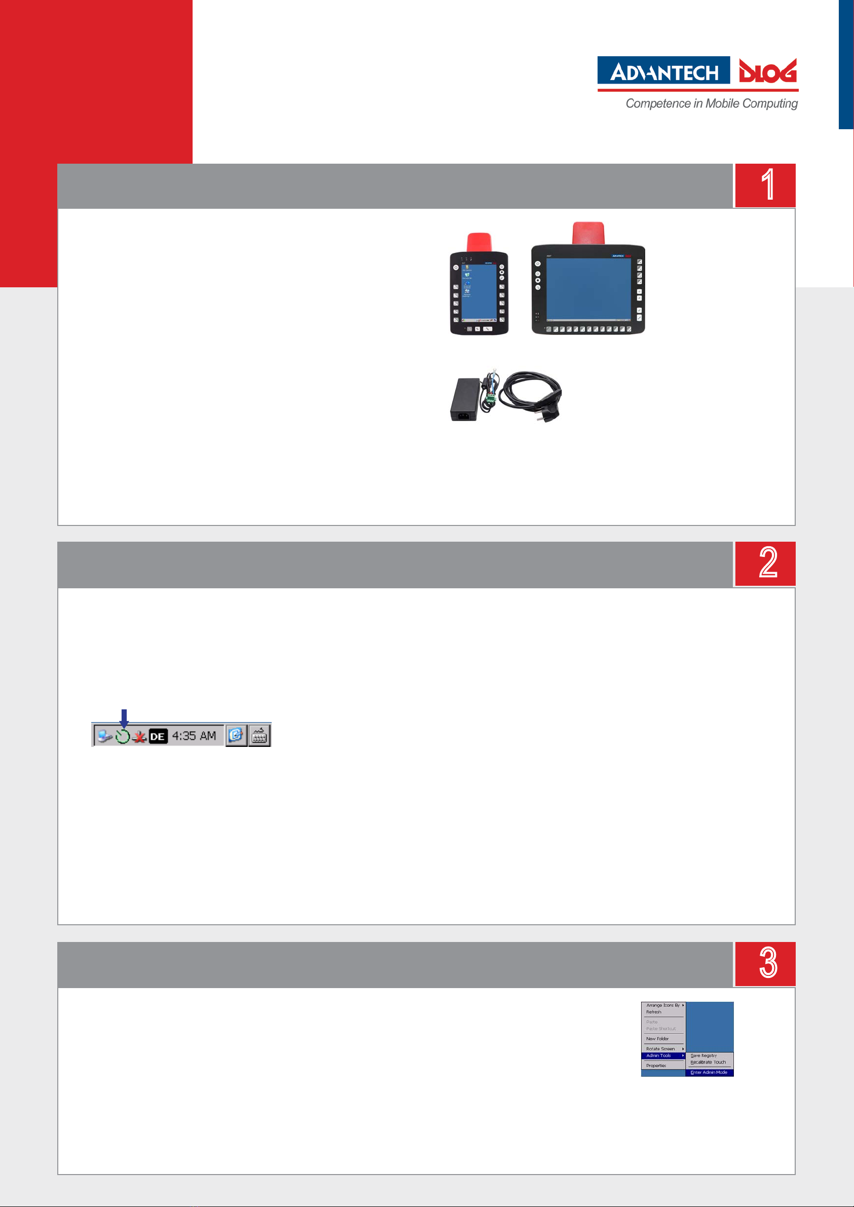
Prerequisites:
• Advantech-DLoG power supply cable
• Advantech-DLoG Preconverter (a special table supply power unit),
to connect the XMT 5 to an AC power supply.
The Preconverter is specially prepared to simulate a vehicle’s
ignition signal: DC+ and Ign are connected with the +Pole of the power supply.
• If you want to operate the XMT 5 using an external mouse or
keyboard, connect this before switching on the device.
3
Rotate Screen and Admin Tools
2
Conguration with neXt Cong
Power supply / Switch on the device
• Connect the XMT 5 to the power supply using an Advantech-DLoG Preconverter.
• Press the <Power>-key (for a short time; max. 1 second).
• The XMT 5 will start.
You can open the Rotate Screen and Admin Tools (manage user rights) functions
via the XMT 5 context menu.
• The context menu can be opened on the XMT 5 screen with the
right mouse button or by pressing the touch screen (min. 2 sec.).
The following functions and others are available:
• Rotate Screen – To rotate the current display
• Admin Tools | Recalibrate Touch – To recalibrate the touch screen
• Don‘t forget: SaveRegistry must be executed to save new calibration data.
• Admin Tools | Enter Admin Mode
The Enter Admin Mode function
opens the XMT 5 Security Shell.
The Security Shell is used to protect
the system against unintended changes
by standard users.
Caution: You must restart the computer
after setting up the security shell.
!Notice: The XMT 5 series is equipped with an integrated, galvanic isolated power
supply for direct voltage. 12/24 VDC and 24/48 VDC models are available.
The output voltage of the Preconverter must be compatible with the input voltage
of the XMT 5. If it is not, the XMT 5 may become badly damaged.
Preconverter and Power supply
cable for XMT 5 Series
XMT 5 Series: XMT 5/7 and XMT 5/10
Your XMT 5 is equipped with the conguration program „DLoG neXt Cong“. You can de-
ne the display brightness, automatic switch-off and front key assignment and other settings
with this program.
Only system administrators may congure the XMT 5.
a) Log on as an administrator
• Click the green neXt Cong icon in the task bar:
NeXt Cong will start.
• Open the menu item Advanced | Change Mode.
• Click Change Mode.
• Switch to Admin Mode. The passwort is: „gold“
• Save the setting.
The neXt Cong icon in the task bar will now be yellow.
Admin Mode is active.
You can now congure the automatic switch-off and the front keys.
b) Congure the automatic switch-off function
Each XMT 5 has been equipped with an automatic shutdown function. This function has
already been pre-congured and governs the power-up and shutdown procedures for the
XMT 5 connected to a car ignition.
The precongured settings for each XMT 5 must be adapted for each customer.
• Open the Switch-Off menu in neXt Cong.
• Check and congure the settings.
• Save your settings
c) Program the keys on the front of the XMT 5
• Open the Set Front Keys menu in neXt Cong.
An interactive graphic appears with the available keys for the XMT 5.
• You can assign specic keyboard commands or program requests
to the front keys there.
• Save your settings
Tip: The Set Front Key settings for an XMT 5 can be exported as a cong le and copied
quickly and easily to other devices. You can nd more details in the XMT 5 manual
(available from the Advantech-DLoG Download Center).
!Notice: If the XMT 5 is congured for switching on with an ignition signal, the
ignition signal must be connected to the power supply plug.


