manuals.online logo
Brands
  1. Home
  2. •
  3. Brands
  4. •
  5. Advantech
  6. •
  7. PCI Card
  8. •
  9. Advantech PCM-3614I Installation and operation manual

Advantech PCM-3614I Installation and operation manual

Other Advantech PCI Card manuals

Advantech MIO-5393 User manual

Advantech

Advantech MIO-5393 User manual

Advantech PCA-5610 Installation and operation manual

Advantech

Advantech PCA-5610 Installation and operation manual

Advantech PCIE-1762H User manual

Advantech

Advantech PCIE-1762H User manual

Advantech PCI-1752 User manual

Advantech

Advantech PCI-1752 User manual

Advantech MIC-3640 User manual

Advantech

Advantech MIC-3640 User manual

Advantech PCI-1712 Installation and operation manual

Advantech

Advantech PCI-1712 Installation and operation manual

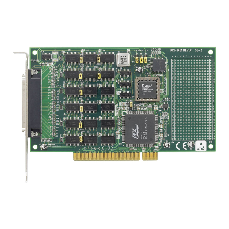
Advantech PCI-1751U User manual

Advantech

Advantech PCI-1751U User manual

Advantech PCIE-1758 Series User manual

Advantech

Advantech PCIE-1758 Series User manual

Advantech PCI-1752U User manual

Advantech

Advantech PCI-1752U User manual

Advantech PCI-1710U-DE User manual

Advantech

Advantech PCI-1710U-DE User manual

Advantech ARK-5261 Installation and operation manual

Advantech

Advantech ARK-5261 Installation and operation manual

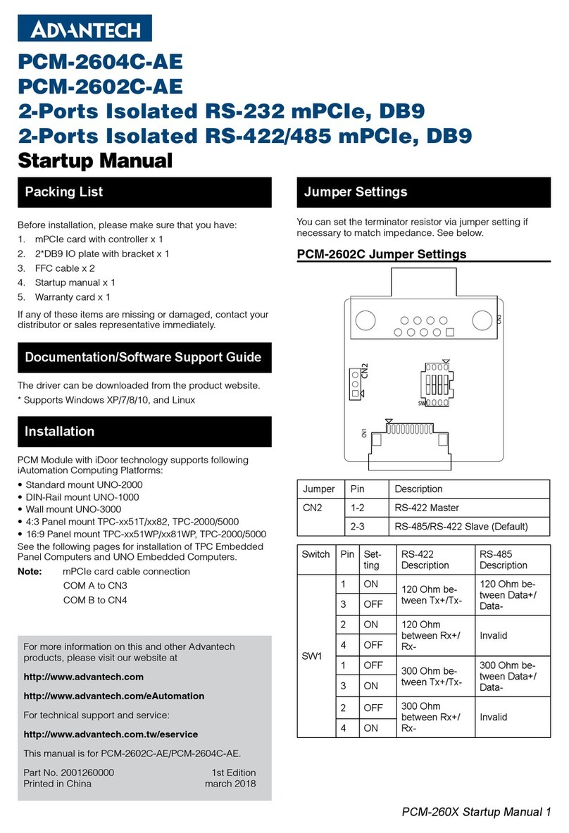
Advantech PCIE-1730H-AE User manual

Advantech

Advantech PCIE-1730H-AE User manual

Advantech B+B SmartWorx McPC/Giga-MediaLinX User manual

Advantech

Advantech B+B SmartWorx McPC/Giga-MediaLinX User manual

Advantech PCI-1751 User manual

Advantech

Advantech PCI-1751 User manual

Advantech PCI-1761 User manual

Advantech

Advantech PCI-1761 User manual

Advantech PCI-1240 User manual

Advantech

Advantech PCI-1240 User manual

Advantech PCI-1724U User manual

Advantech

Advantech PCI-1724U User manual

Advantech PCI-1742U Installation and operation manual

Advantech

Advantech PCI-1742U Installation and operation manual

Advantech PCIE-1754 User manual

Advantech

Advantech PCIE-1754 User manual

Advantech MIC-3950 User manual

Advantech

Advantech MIC-3950 User manual

Advantech PCI-1711U Series User manual

Advantech

Advantech PCI-1711U Series User manual

Advantech AIMB-228 User manual

Advantech

Advantech AIMB-228 User manual

Advantech PCI-1706U User manual

Advantech

Advantech PCI-1706U User manual

Advantech PCI-1737U Installation and operation manual

Advantech

Advantech PCI-1737U Installation and operation manual

Popular PCI Card manuals by other brands

Avermedia ER330 Quick installation guide

Avermedia

Avermedia ER330 Quick installation guide

ERMA SSI 1417 instruction manual

ERMA

ERMA SSI 1417 instruction manual

SIIG CyberSerial Dual PCI Software installation

SIIG

SIIG CyberSerial Dual PCI Software installation

Airlink101 AWLH3028 user manual

Airlink101

Airlink101 AWLH3028 user manual

Dolphin MXH932 user guide

Dolphin

Dolphin MXH932 user guide

I-Bus IBC2602 user guide

I-Bus

I-Bus IBC2602 user guide

ICP DAS USA PCI-1002H user manual

ICP DAS USA

ICP DAS USA PCI-1002H user manual

Exsys EX-60102 manual

Exsys

Exsys EX-60102 manual

Chelsio Communications T5 Series Installation and user guide

Chelsio Communications

Chelsio Communications T5 Series Installation and user guide

Conrad Electronic 97 46 71 operating instructions

Conrad Electronic

Conrad Electronic 97 46 71 operating instructions

Micro Innovations USB650A Quick installation guide

Micro Innovations

Micro Innovations USB650A Quick installation guide

KTI Networks KF-310 user guide

KTI Networks

KTI Networks KF-310 user guide

Intellinet 500517 user manual

Intellinet

Intellinet 500517 user manual

Asus SpaceLink WL230 user manual

Asus

Asus SpaceLink WL230 user manual

SIIG SC2475 Quick installation guide

SIIG

SIIG SC2475 Quick installation guide

TRENDnet TEW-703PI Quick installation guide

TRENDnet

TRENDnet TEW-703PI Quick installation guide

Pericom PI7C7100 manual

Pericom

Pericom PI7C7100 manual

ADLINK Technology cPCI-3548 user manual

ADLINK Technology

ADLINK Technology cPCI-3548 user manual

manuals.online logo
manuals.online logoBrands
  • About & Mission
  • Contact us
  • Privacy Policy
  • Terms and Conditions

Copyright 2025 Manuals.Online. All Rights Reserved.

1 Startup Manual All product specifications are subject to change without notice.
STARTUP MANUAL
PCM-3614I
4-port RS-232/422/485 Module
The PCM-3614I is a PCI-104 compatible module
with 4 individually configurable RS-232/422/485
ports. The PCM-3614I also features high
transmission speeds, independent/shared IRQ’s, a
high-performance 16C550 UART communication
chip with 16-byte FIFO to reduce CPU load, and
more. These function settings include Standard/
Enhance, Independent/Shared IRQ & Speed modes.
We carefully inspected the PCM-3614I both
mechanically and electrically before we shipped it.
It should be free of marks and scratches and in per-
fect electrical order on receipt.
Handle the board only by its edges. The static
charge on your body may damage its integrated cir-
cuits. Keep the card in its anti-static package when-
ever it is not installed. You can use this package to
return the card if it should need repair.
• 4 Independent RS-232/422/485 serial ports
• Automatic RS-485 data flow control
• Transmission speeds up to 921.6 Kbps
• Shared IRQ settings for each port
• Built-in terminal resistors
• LED indicators: TX, RX
• Bus interface: PCI-104
• Number of ports: 4
• UART: 16C550
• IRQ: 3, 4, 5, 6, 7, 9, 10, 11, 12, 15
• Data bits: 5, 6, 7, 8
• Stop bits: 1, 1.5, 2
• Parity: none, even, odd
• Speed (bps): 50 ~ 921.6K
• Connectors: DB-9 male
• Signal:
RS-422: TxD+, TxD-, RxD+, RxD-, GND
RS-485: DATA-, DATA+, GND
RS-232: TxD, RxD, RTS, CTS, DTR, DSR,
DCD, RI, GND
• Operating Temperature: -40~85°C (-40~185°F)
• Storage Temperature: -40~85°C (-40~185°F)
• Operation Humidity: 0% ~ 90%
|Relative Humidity, non-condensing
Card Configuration
The max configuration for the PCI bus of PCI-104
modules is FOUR plus the host board. If you stack
more than one PCI-104 module to a host board be
sure to set the modules to different PCI numbers
through SW2.
SW1 Settings
1. Use pin 5 ~ 8 on SW1 to determine mode of
port 0 to port 3 as RS-422 or RS-485. The pin
number and port number are mapping directly.
• “ON” is RS-485 mode. “OFF” is RS-422 mode.
• For example, pin 5 is mapping to port 0. So if
you set pin 5 to “ON”, it means port 0 is RS-
485 mode.
• If you set pin 5 to “OFF”, it means port 0
becomes RS-422 mode.
Introduction Specifications
Initial Inspection
Features
Notes
For more information on this and other Advantech
products, please visit our websites at:
http://www.advantech.com
http://www.advantech.com/eAutomation
For technical support and service:
http://www.advantech.com/support/
This startup manual is for PCM-3614I.
Part No: 2003361400 1st Edition
April 2013
RS-232 RS-422 RS-485
N/A 1,2,3,4,ON: Master
5,6,7,8 OFF
1,2,3,4,OFF: Slave
(Auto)
1,2,3,4,OFF
5,6,7,8 ON
All manuals and user guides at all-guides.com
all-guides.com
2 Startup Manual
2. When you set selected port as RS-422 mode, use pin
1 ~ 4 on SW1 to determine port 0 to port 3 as Master
or Auto mode.
• (Auto mode means corresponding port will auto-
matically configure itself as master or slave). The
pin number and port number are mapping directly.
• “ON” is Master mode. “OFF” is Auto mode.
• For example, when port 0 is set as RS-422 mode.
pin 1 is mapping to port 0. So if you set pin 1 to
“ON”, it means port 0 is Master mode.
• If you set pin 1 to “OFF”, it means port 0 becomes
Auto mode.
SW2 Settings
Hardware Installation
Installing the Module on a CPU Card:
1. Turn the PC power off. Turn the power off to any
peripheral devices such as printers and monitors.
2. Disconnect the power cord and any other cables from
the back of the computer.
3. Remove the system unit cover
4. Remove the CPU card from the chassis (if necessary)
to gain access to the card’s PCI-104 connector.
5. Screw the brass spacer (included with the module)
into the threaded hole on the CPU card. Do not
tighten too much, or the threads may be damaged.
6. Carefully align the pins of the PCM-3614I with the
PCI-104 connector. Slide the module into the con-
nector, do not push too hard.
7. Secure the module to the CPU card to the threaded
hole in the CPU card using the included screw.
8. Attach any accessories to the PCM-3614I.
9. Reinstall the CPU card and replace the system unit
cover. Reconnect the cables you removed in step 2.
10. Turn the power on.
Connecting to Another PCI-104 Module:
1. Insert the pins of connector CN15 into the piggy-
back connector on the other PCI-104 module.
2. Screw the PCM-3614I to the brass spacer. This com-
pletes the hardware installation
Pin Assignments and Jumper Settings
The function of PCM-3614I is adjustable by the follow-
ing jumpers.
Jumper Settings of CN1~CN10
CN and COM Port Mapping
The following table and figure shows pin assignments
for the DB9 connector.
12PCINumber
OF OFF 0
ON OFF 1
OFF ON 2
ON ON 3

Warning! Turn off PC whenever you install, remove connect
or disconnect cables to PCM-3614I
RS-232
CN3,CN4,CN5
Short pins:1-2, 3-4,5-6,7-8,9-10
CN2
Short pins:1-2, 3-4,5-6,7-8,9-10
CN1
Open
RS-422
CN3,CN4,CN5
Short pins:11-12,13-14,15-16,17-18,19-20
CN2
Open
CN1
Short pins:1-2, 3-4,5-6,7-8,9-10
RS-485
CN3,CN4,CN5
Short pins:11-12,13-14,15-16,17-18,19-20
CN2
Open
CN1
Short pins:1-2, 3-4,5-6,7-8,9-10
CN Number COM Port Number
10
31
22
43
All manuals and user guides at all-guides.com
Startup Manual 3
Pin Assignments of RS-232 DB9 Connector
Pin Assignments of RS-422/485 DB9 Connector
Pin Assignments of RS-422/485 Configuration
Pin RS-232
1 DCD
2RxD
3TxD
4DTR
5GND
6DSR
7RTS
8CTS
9RI
Pin RS-422/485
1 TX-(DATA-)
2 TX+(DATA+)
3RX+
4RX-
5GND
6RTS-
7RTS+
8CTS+
9CTS-
Pin Description Pin Description
Port 0
Data- 1 TX- 2 RTS-
Data+ 3 TX+ 4 RTS+
5RX+ 6CTS+
7RX- 8CTS-
9 GND 10 NC
Port 1
Data- 11 TX- 12 RTS-
Data+ 13 TX+ 14 RTS+
15 RX+ 16 CTS+
17 RX- 18 CTS-
19 GND 20 NC
Port 2
Data- 21 TX- 22 RTS-
Data+ 23 TX+ 24 RTS+
25 RX+ 26 CTS+
27 RX- 28 CTS-
29 GND 30 NC
Port 3
Data- 31 TX- 32 RTS-
Data+ 33 TX+ 34 RTS+
35 RX+ 36 CTS+
37 RX- 38 CTS-
39 GND 40 NC
All manuals and user guides at all-guides.com