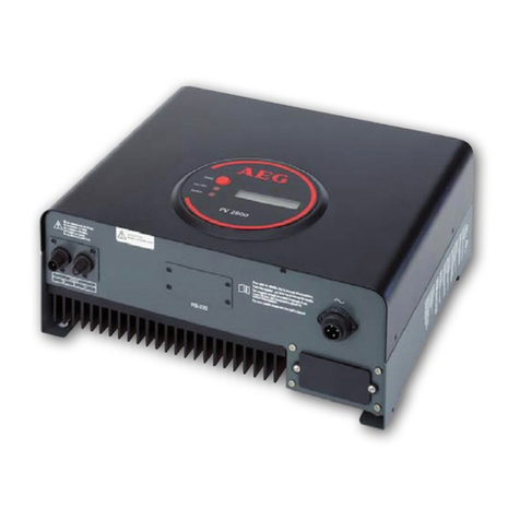
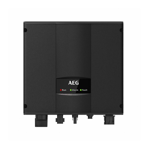
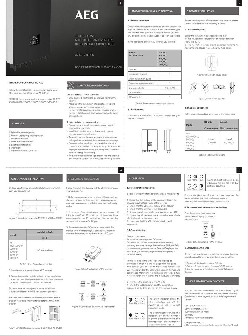
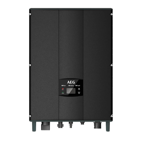
AEG Protect PV 4600 User manual

1
OPERATING INSTRUCTIONS
En
PRotEct PV 4600
on-gRid solaR inVERtER
Version 17.03.2011 / Rev 04

2
Read this User Manual before you start 3
1. Safety Instructions 4
2. Limited Warranty 5
3. Overview 8
3.1 Introducing the grid-connected PV System 8
3.2 Introducing the Grid PV System 9
3.3 Front Panel LEDs 10
4. Features 11
5. Installation 12
5.1 Inside Protect PV 4600 Package 12
5.2 Mounting your Protect PV 4600 12
5.3 Connecting the AC-Output Cable 17
5.4 Connecting the PV-Panel 20
5.5 Connecting to the connection unit 21
5.6 Installation checklist 22
6. Operation of the Protect PV 4600 24
6.1 Auto-power 24
6.2 Operating Modes 24
6.3 Using the LCD Display 26
6.4 Maximum Power Point Tracking (MPPT) 30
6.5 LCD Display Messages 31
7. Communication Interface 33
7.1 RS232 33
7.2 Optional Communications Interface 33
8. Troubleshooting 34
9. Specifications 36
10. Compliance of Standards 37
11. Load Graph and Efficiency Graph 38
CONTENTS

3
READ THIS USER MANUAL BEFORE YOU START
Congratulations for purchasing your Protect PV 4600 grid-connected
PV-Inverter from AEG Power Solutions GmbH (referred to in this
manual as “PV-Inverter”, or simply the “device”). This PV-Inverter is a
highly reliable product due to its innovative design and perfect quality
control. The device is dedicated to high-demand, grid-linked PV systems.
This manual contains important information regarding installation and
safe operation of this unit. Be sure to read this manual carefully before
using your PV-Inverter.
If you encounter any difficulties during installation or operation, please
refer to this manual before contacting your local dealer or representa-
tive. To obtain the latest manual and product information, please con-
tact the inverter’s manufacturer.
Thank you for choosing our product. Please keep this manual on hand
for quick reference. Start enjoying Protect PV 4600 and your life!

4
1. Risk of ElEctRic shock:
Alternating Current (AC) and Direct Current (DC) sources are termi-
nated in this device. To prevent risk of electric shock during mainte-
nance or installation please ensure that all AC and DC terminals are
disconnected.
2. handling youR PV-inVERtER:
The PV-Inverter should only be handled by qualified service person-
nel. When the PV-panel is exposed to sunlight and connected to the
device, it generates a DC voltage charging the DC link capacitors.
After disconnecting the PV-Inverter from the power supply and PV-
panel, electrical charge can still reside in the DC link capacitors. The
device shall be touched by qualified personnel earliest 60 minutes
after disconnecting.
3. Public suPPly mains only:
The PV-Inverter is designed to feed AC power directly to the public
supply mains. Do not connect the AC-output of this device to any
private AC equipment.
4. bEwaRE of hot suRfacEs:
Although designed to meet international safety standards, the PV-
Inverter can become hot during operation. Do not touch the heat-
sink or peripheral surfaces during or shortly after operation.
1. SAFETY INSTRUCTIONS

5
2. LIMITED WARRANTY
The limited warranty provided by AEG Power Solution (“AEG PS”) in
this Statement of Warranty applies only to Equipment purchased for
residential, commercial or industrial use in the ordinary course of the
business.
tERms of waRRanty
AEG PS warrants that it is sufficiently experienced, properly qualified,
registered, licensed, equipped, organized and financed to perform the
Work in compliance with the terms of this Agreement.
AEG PS warrants that the Equipment shall be free from defects in de-
sign, materials and workmanship for a period of sixty (60) months from
the date of commissioning when AEG PS authorized service personnel
performed the commissioning and start-up of the Equipment, but not
longer than sixty six (66) months from the date of notification that the
goods are ready for dispatch, whichever occurs first.
In the event that the Equipment fails to meet the foregoing warranty,
AEG PS undertakes to repair and/or replace any part found to be faulty
due to errors in design or manufacture, or to be made of faulty mate-
rials if trained & authorized AEG PS personnel has conduct commissio-
ning and start-up of the Equipment.
An AEG PS Commissioning and Start-Up Service must be performed/
completed by AEG PS or by authorized service personnel. If not, the
on-site Warranty will be voided and replacement of defective parts only
will be covered.
AEG PS shall have no liability and no obligation to repair the installed
Equipment if non-authorized personnel performed the start-up and
such start-up caused the Equipment to be defective.
In addition, the Warranty does not cover defects originating from the
materials provided by the Purchaser, a design imposed by the Pur-
chaser, incidents brought about by contingencies or acts of God or
any other cause the vendor could not reasonably be expected to fore-
see or whose consequences it could not prevent, repairs or replace-
ments imposed by normal wear and tear of the equipment, damage or
accidents brought about by the Purchaser‘s actions, such as negligence,
connection error, failure to follow instructions for maintenance, abnor-
mal use due in particular to electrical or mechanical overload.

6
Any parts furnished under this warranty may be new or factory-remanu-
factured. Repair or replacement of a defective Equipment or part there-
of does not extend the original warranty period.
The AEG PS reserves the rights to modify if necessary the mechanism
of the equipment in order to fulfil this Agreement.
waRRanty claims PRocEduRE
Should you be experiencing technical issues with your inverters, please
have your installer or reseller report the case to the country specific
AEG PS hotline. AEG PS service hotline numbers are available by con-
sulting the www.aegps.com website. To better assist you, your installer
will require having the following information readily available:
- Caller’s contact information
- Product type and serial number
- Installation date
- Problem occurrence date
- Problem description and error code
Should the service hotline conclude to a replacement of the inverter,
your installer or reseller will be required to download and complete the
appropriate RMA (Return Material Authorisation). A PDF version of the
RMA document can be downloaded from the www.aegps.com website.
The system replacement will be facilitated by following and accepting
the general terms and conditions mentioned on the second page of the
RMA document.
Exclusions
AEG PS shall not be liable under the Warranty if its testing and exa-
mination discloses that the alleged defect in the Equipment does not
exist or was caused by your or any third person’s misuse, negligence,
improper installation or testing, unauthorized attempts to repair or
modify, or any other cause beyond the range of the intended use, or
by accident, fire, lightning or other hazard.
There are no warranties, expressed or implied, by operation of law or
otherwise, of Equipment sold, serviced or furnished under this Agree-
ment or in connection herewith. AEG PS disclaims all implied Warran-
ties of merchantability, satisfaction and fitness for a particular purpose.
The AEG PS express warranties will not be enlarged, diminished, or
affected by and no obligation or liability will arise out of AEG PS ren-
dering technical or other advice or service in connection with the Equip-
ment. The foregoing warranties and remedies are exclusive and in lieu
7
of all other warranties and remedies. The warranties set forth above,
constitute sole liability of AEG PS and purchaser’s exclusive remedy
for any breach of such Warranties. The warranties extend only to pur-
chasers and are not extended to any third parties.
In no event shall AEG PS, its officers, directors, affiliates or employees
be liable for any form of indirect, special, consequential or punitive
damages arising out of the use, service or installation of the Equipment,
whether such damages arise in contract or tort, irrespective of fault,
negligence or strict liability or whether AEG PS has been advised in
advance of the possibility of such damage.
waRRanty ExtEnsion
The original factory warranty can be extended by purchasing additional
Extended Warranty Program which extends factory warranty by five (5)
years from the date the original factory warranty is ending and guaranty
repair and/or replacement of defective parts. Travelling time, expenses
and board and accommodation costs will be charged to the Purchaser.
The Extended Warranty must be purchased within the first 12 months
of the inverter purchase.
The Extended Warranty Program does not cover failure due to com-
missioning or Start-Up by non-authorized personnel, improper opera-
tion or use of the equipment, lack of maintenance, alterations to origi-
nal design or a change in location or operating use.
Extended warranty doesn’t cover wear and tear parts such as cooling
fans.
The other terms of Extended Warranty Program are defined in the Terms
of warranty section.

8
3. OVERVIEW
3.1 intRoducing thE gRid-connEctEd PV systEm
The grid-connected PV System is mainly composed of 4 parts: the
PV-panels, the PV-Inverter, the AC-Connection Unit (the connection
Interface) and a connection to the Public Grid.
When a PV-panel is exposed to sunlight and connected to an inverter,
it generates DC power. The PV-Inverter converts DC to AC and feeds in
to the Public Grid via the AC-Connection unit.
Inverter
PV-Panel DC-Input AC
Output
AC-Connec-
tion Unit
Grid (Public Utility)
Feeding AC power to
Public Utility only

9
(1) Con-
nection
Panel
3.2 intRoducing thE gRid PV systEm
(2) Heat-sink
(3) 3-pairs of DC inputs
(4) AC Output (5) Optional Commu-
nication Port with
Cover
(6) RS232 Connector
(7) Front LCD Display
Panel
PROTECT PV 4600 INVERTER
(1) Connection Panel: The connection panel contains DC and AC termi-
nals, and communication ports as detailed below.
(2) Heat-sink: Part to dissipate heat produced by the inverter
(3) 3 pairs of DC-input terminals: Each input pair consists of positive and
negative terminals. Refer to Installation Section for set-up information.
(4) AC-Output: Delivering AC to the Public grid.
(5) Optional Communication Slot and Cover: An optional port to extend
the communication interface, for example for connecting a RS485
card. The port is protected by a water-proof cover.
(6) RS232 Port: Interface allows communication with computer via RS232
serial port.
(7) LCD Display: Device to display inverter operation status.

10
3.3 fRont PanEl lEds
There are 2 LED’s on Protect PV 4600, one is green and the other is red.
Normally, only the green LED is on during operation. The indicated
status are explained as follows:
Power on (green LED): The LED lights, if Protect PV is running. The
LED lights not, if no power is provided to Protect PV inverter. In this
case, Protect PV 4600 is in shutdown mode.
Fault (red LED): The LED lights, if the inverter is in “fault” or “failure”
condition. To see the conditions, please refer to section 8:
Function Button
Power-on LED
Fault LED
LCD Display
Power-on
Fault

11
• Very high conversion efciency (> 96%)
• 3 MPP tracker (Maximum Power Point), independent or parallel
operation
• IP65 compliant for outdoor application
• Embedded LCD, displaying status and system information
• Fanless design, quiet operation
• Stylish design
• Compact and unobtrusive
• High reliability
• Easy installation
• Maintenance free
• Standard RS232, optional RS485 and others
• Embedded ENS, complying with VDE 0126
• Internal GFCI (Ground Fault Current Interrupter)
4. FEATURES

12
5. INSTALLATION
5.1 insidE PRotEct PV 4600 PackagE
The following items are included in your Protect PV 4600 Package:
(1) Protect PV 4600 PV-Inverter
(2) Installation and Operation Manual
(3) 4 Mounting Screws and 4 Blade receptacle
(4) 2 Safety-lock screws
(5) 3-hole Rubber Bushing
(6) Mounting Bracket
5.2 mounting youR PRotEct PV 4600
SUGGESTIONS BEFORE MOUNTING
To obtain optimal results from your PV-Inverter, please consider the
following guidelines before installing the device:
Do not expose the PV-Inverter to direct sunlight. Direct sunlight increa-
ses the internal temperature that may reduce conversion efficiency.
- Check the ambient temperature of installation is within specified range
-20 ~ +55 °C.
- The AC grid voltage is between 196 and 253 VAC, 50/60 Hz.
- Electric utility company has approved the grid connection.
- Qualified personnel are performing the installation.
- Adequate convection space surrounds the inverter.
- Inverter is being installed away from explosive vapors.
- No flammable items are to be near the inverter.
Protect PV can be installed and operated at locations where the am-
bient temperature is up to 55 °C. However, for optimal operation, it is
recommended that Protect PV is installed where the ambient tempera-
ture is between 0 ~ 40 °C.

13
mounting PRotEct PV to thE wall
1. Choose a dry place, out of direct sunlight with ambient temperature
between 0 and 40 °C.
2. Select a wall or solid, vertical surface which is strong enough to sup-
port the inverter.
3. The PV-Inverter requires adequate cooling space for heat dispersal.
Reserve at least 20 cm above and below the inverter.
Minimum space 20 cm
Minimum space 20 cm

14
4. Mark the positions of the 4 outer mounting holes onto the wall with
the bracket as illustrated:
USING THE OUTER MOUNTING HOLES
Upper Mounting Holes
Lower Mounting Holes
Mounting Bracket

15
5. To install the device to a narrow surface, mark the 4 central holes at
the back of the bracket.
USING THE CENTRAL MOUNTING HOLES
6. Drill the 4 marked holes in the wall, and then drive in the 4 Snap
Bushings. Now insert the screws and tighten them.
6. Drill the 4 marked holes in the wall, and then drive in the 4 Snap
Bushings. Now insert the screws and tighten them.
Upper Central
Mounting
Holes
Lower Central
Mounting
Holes
OUTER MOUNTING HOLES
CENTRAL MOUNTING HOLES

16
7. Mount the PV-Inverter onto the bracket as illustrated:
8. Insert the Safety Lock screws to fix the PV-Inverter in place.
9. Install the device vertically to ensure the device is properly fixed to
the bracket.
Safety Lock Screw
LCD Display

17
5.3 connEcting thE ac-outPut cablE
Connect your PV-Inverter to the AC-Connection unit via the AC-output
cable as following steps:
(1) Open the AC-output cover with
a screw driver.
(2) Draw out the AC Connector set
from the Inverter.
AC-Output Connector
AC-Output Cable
(≥2.0 mm²)
AC connection unit
(consisting of breaker,
fuse, terminals etc.)

18
AC cable lock
Rubber Plug
(no hole in it)
3-hole Rubber Bushing
(3) Unscrew the cable lock and prepare
your AC cable.
(4) Remove the rubber plug from inside the
AC connector socket.
(5) Insert the provided rubber bushing
with three holes into the AC connector
socket.

19
(7) Fix the brown wire to L (Line); the blue
wire to N (Neutral); and the yellow-green
wire to G (Ground).
All three wires should be firmly connec-
ted.
(8) After checking the 3 wires are fixed pro-
perly, push the AC-output connection
set back in to the Connection Panel.
Drive the 4 screws back to fix the set.
(6) Now insert the three wires of the AC
cable into the bushing holes.
L for Line
N for Neutral
G for Ground

20
(9) Now screw the Connector
Locker in tight to fix the
bushing and cable.
(1) First make sure that the maximum open circuit voltage Voc of each
PV string is below 750VDC UNDER ANY CONDITION.
(2) Always connect PV-Panel positive (+) terminal to PV-Inverter DC
positive (+) terminal, and the PV-Panel negative (-) terminal to PV-
Inverter DC negative (-) terminal.
(3) Each set of PV-Inverter DC terminals takes a maximum DC input
of 8.5 A. As a result, 3 pairs of PV-Inverter DC terminals can take a
combined input of up to 25.5 A.
5.4 connEcting thE PV-PanEl
Table of contents
Other AEG Inverter manuals
Popular Inverter manuals by other brands

Growatt
Growatt MOD 3-15KTL3-X quick guide

SMA
SMA SUNNY TRIPOWER CORE1STP 50-40 Quick reference guide

SolarEdge
SolarEdge SE5000H-AU installation guide

Generac Power Systems
Generac Power Systems Liquid Cooled Gas Engine Generator Sets None Specification sheet

AimLite
AimLite MINI-INVERTER 1440 installation instructions

Hobart
Hobart JET-EX 4 Operation and maintenance manual