AEG AS-IC01-2 Series User manual

THREE-PHASE GRID-TIED SOLAR INVERTER
AS-IC01-2 (12 kW TO 30 kW)
INSTALLATION INSTRUCTIONS
PD201808 AEG GRID-TIED THREE-PHASE SOLAR INVERTER (12-30 kW) V.2-18 EN

1
PD201808 AEG GRID-TIED THREE-PHASE SOLAR INVERTER (12-30 kW) V.2-18 EN
1
AEG GRID-TIED THREE-PHASE SOLAR INVERTER INSTALLATION MANUAL
Thank you for choosing the reliability of AEG grid-tied solar inverters!
This installation manual is intended for dealers and installers involved in the planning, installation and commissioning of
photovoltaic systems deploying AEG solar inverters. These instructions are meant to provide you with valuable infor-
mation to ensure that your PV installation runs smoothly and achieves optimal yields over its whole lifecycle.
AEG grid-tied solar inverters are tested and approved by acknowledged independent certification authorities and can
only be installed by qualified professional companies. Please observe the standards and regulations applying to photo-
voltaic systems in the relevant countries, as well as the rules of the employers’ liability insurance associations for accident
protection. Failure to comply with these can result in major injuries and damage.
Product series: AEG grid-tied three-phase solar inverters AS-IC01-xxx-2 (12 kW to 30 kW)

2
PD201808 AEG GRID-TIED THREE-PHASE SOLAR INVERTER (12-30 kW) V.2-18 EN
2
Table of Contents
Table of Contents ............................................................................................................................................................................................................................................................................................. 2
1. Safety Precautions..................................................................................................................................................................................................................................................................................... 4
1.1 Icons................................................................................................................................................................................................................................................................................................ 4
1.2 Safety Guidelines.............................................................................................................................................................................................................................................................................. 4
1.2.1 Delivery and Installation ................................................................................................................................................................................................................................................ 5
1.2.2 Grid-tied operation............................................................................................................................................................................................................................................................. 6
1.2.3 Maintenance and Inspection....................................................................................................................................................................................................................................6
1.2.4 Storage........................................................................................................................................................................................................................................................................................... 7
1.2.5 Product End of Life............................................................................................................................................................................................................................................................ 7
2. Product Overview........................................................................................................................................................................................................................................................................................ 8
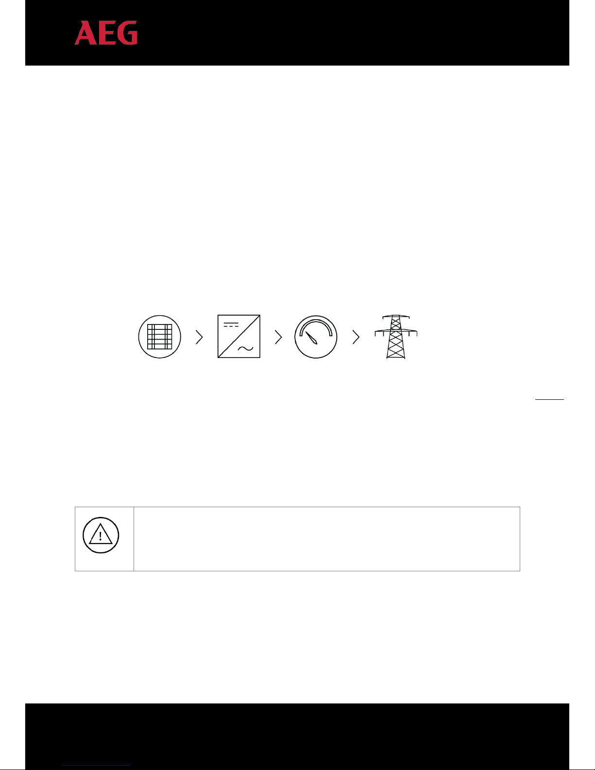
2.1 Solar Grid-tied Power Generation Systems...........................................................................................................................................................................................................8
2.1.1 Application................................................................................................................................................................................................................................................................................... 8
2.1.2 Supported grid connection structure..............................................................................................................................................................................................................9
2.2 Product Appearance.................................................................................................................................................................................................................................................................. 10
2.3 Labels......................................................................................................................................................................................................................................................................................................... 11
2.3.1 Packaging labels ................................................................................................................................................................................................................................................................. 11
2.3.2 Product label..........................................................................................................................................................................................................................................................................12
2.3.3 Product models ...................................................................................................................................................................................................................................................................13
2.4 Technical parameters ...............................................................................................................................................................................................................................................................13
2.5 Dimensions and weight...........................................................................................................................................................................................................................................................15
3. Installation.........................................................................................................................................................................................................................................................................................................15
3.1 Unpacking inspection.................................................................................................................................................................................................................................................................15
3.2 Before installation ................................................................................................................................................................................................................................................................ 18
3.2.1 Installation tools.................................................................................................................................................................................................................................................................. 18
3.2.2 Installation place................................................................................................................................................................................................................................................................ 18
3.2.3 Connection cables.......................................................................................................................................................................................................................................................... 20
3.2.4 Miniature circuit breakers....................................................................................................................................................................................................................................... 20
3.3 Mechanical installation.............................................................................................................................................................................................................................................................21
3.3.1 Installation of three-phase inverters..............................................................................................................................................................................................................21
3.4 Electrical installation.................................................................................................................................................................................................................................................................. 23
3.4.1 Connection of solar modules................................................................................................................................................................................................................................ 23
3.4.2 AC connection of three-phase inverters 12 kW to 30 kW ......................................................................................................................................................25
4. Operation......................................................................................................................................................................................................................................................................................................... 26

3
PD201808 AEG GRID-TIED THREE-PHASE SOLAR INVERTER (12-30 kW) V.2-18 EN
3
4.1 Inspection before operation.............................................................................................................................................................................................................................................. 26
4.2 Grid-tied operation..................................................................................................................................................................................................................................................................... 27
4.3 Stopping................................................................................................................................................................................................................................................................................................ 28
4.4 Maintenance..................................................................................................................................................................................................................................................................................... 28
4.4.1 Regular maintenance .................................................................................................................................................................................................................................................. 28
4.4.2 Maintenance guide....................................................................................................................................................................................................................................................... 29
5. Display panel..................................................................................................................................................................................................................................................................................................31
5.1 LED indicators ...................................................................................................................................................................................................................................................................................31
5.2 Operation panel.............................................................................................................................................................................................................................................................................. 33
5.3 LCD display......................................................................................................................................................................................................................................................................................... 33
5.4 Functions operation.................................................................................................................................................................................................................................................................. 34
5.4.1 Monitoring parameters.............................................................................................................................................................................................................................................. 34
5.4.2 History......................................................................................................................................................................................................................................................................................... 35
5.4.3 Statistics .................................................................................................................................................................................................................................................................................... 35
5.4.4 Parameter settings......................................................................................................................................................................................................................................................... 35
5.4.5 System Information....................................................................................................................................................................................................................................................... 42
5.4.6 Faults........................................................................................................................................................................................................................................................................................... 42
5.4.7 Inverter control.................................................................................................................................................................................................................................................................. 42
5.4.8 Mode settings..................................................................................................................................................................................................................................................................... 44
5.5 Grid selection.................................................................................................................................................................................................................................................................................... 44
6. Monitoring communication........................................................................................................................................................................................................................................................... 46
6.1 Standard communication..................................................................................................................................................................................................................................................... 46
6.2 Optional communication...................................................................................................................................................................................................................................................... 47
6.3 AEG WiFi200 (AEG WiFi Stick) communication module.................................................................................................................................................................... 47
6.3.1 AEG WiFi Stick product overview.................................................................................................................................................................................................................... 47
6.3.2 Remote Monitoring and Local Monitoring; the AEG InverterControl App and Portal.............................................................................48
7. Troubleshooting....................................................................................................................................................................................................................................................................................... 50
8. Contact.................................................................................................................................................................................................................................................................................................................51
9. Annex: Warranty Card......................................................................................................................................................................................................................................................................... 52

4
PD201808 AEG GRID-TIED THREE-PHASE SOLAR INVERTER (12-30 kW) V.2-18 EN
4
1. Safety Precautions
This section describes relevant warning symbols recurring in the installation and operation manual of AEG three-phase
solar inverters of the series AS-IC01-2. Icons highlight relevant information for the physical and property safety of the
user. Compliance to the provided instructions is essential to prevent physical injury and product damage.
1.1 Icons
Below is a list of the icons used in this manual:
Icon
Meaning
Instruction
Danger Serious physical injury or even death may occur in case of
noncompliance with the requirement.
Warning Physical injury or product damage may occur in case of
noncompliance with the requirement.
Prohibited Damage may occur in case of
noncompliance with the requirement.
Hot surface Product surface may become hot. Do not touch.
Note Useful information for product maintenance and operation is provided
Table 1: Icon meaning
1.2 Safety Guidelines
5 minutes
Look for any visible damage to the package or the product itself. Double-check the order information
and the product nameplate to ensure the products are of the ordered type. Should you find any prob-
lems, contact the shipping company and / or your supplier as soon as possible before attempting
product installation.
Only qualified electricians are allowed to install the inverter.
Do not carry out any wiring and inspection nor change components when the inverter is connected
to power supply. Hazardous voltages may still be present in the inverter even when the AC and DC
main switches are turned off. Ensure that DC and AC side circuit breakers have been disconnected
and wait at least 5 minutes after switching off the inverter to undertake any operation on the inverter.
This ensures that the capacitors are electrically discharged.

5
PD201808 AEG GRID-TIED THREE-PHASE SOLAR INVERTER (12-30 kW) V.2-18 EN
5
The product can cause a DC current to be generated in the external protective earth conductor. In
case of direct or indirect contact, a residual current-operated protective (RCD) or monitoring (RCM)
device is strongly recommend to be used for protection. Only a RCD or RCM of Type B is allowed on
the product’s supply side.
Ensure that there is no electromagnetic interference from other electrical and electronic equipment
at the installation site.
Only use original parts and components. Do not unauthorizedly refit the inverter.
All the electric installation needs to be compliant with the national or local laws and standards.
The temperature of individual parts or the enclosure of the inverter –especially the heat sink– may
become hot during and due to normal operation. Avoid possible burns. Do not touch.
The inverter must be reliably grounded before operation.
Do not unauthorizedly open the inverter cover. The electrical parts and components inside the in-
verter are electrostatic. Take measurements to avoid electrostatic discharge during relevant opera-
tions.
Technical personnel (Operators) who can carry out installation, wiring, commissioning, maintenance,
troubleshooting and replacement of the AEG inverter series must meet the following requirements:
•The Operator has to be professionally trained
•The Operator must read this manual completely and master the related safety precautions
•The Operator needs to be fully familiar with the composition and operating principle of the
whole grid-tied photovoltaic power generation system and related standards of the coun-
tries/regions where the installation / project is located.
•The Operator must wear personal protective equipment.
1.2.1 Delivery and Installation
AEG AS-IC01-2 series of grid-tied three-phase solar inverters are meant
to be deployed only with crystalline silicon solar modules.

6
PD201808 AEG GRID-TIED THREE-PHASE SOLAR INVERTER (12-30 kW) V.2-18 EN
6
Keep the package and unit complete, dry and clean during storage and delivery.
Due to product weight, lifting and installing the inverter requires two workers.
Lift and install the inverter with appropriate tools to ensure safe and normal operation and avoid
physical injury or death. Workers are also required to follow mechanical protective measures, such as
wearing protective shoes and work clothes.
Only qualified electricians are allowed to install the inverter.
Do not put or install the inverter on or close to combustible materials.
Keep the installation site away from children and public access.
Remove metal accessories such as rings or bracelets before installation and electrical connection to
avoid electric shock.
Cover solar modules with light-tight materials. When exposed to light or sunlight, solar modules will
generate potentially dangerous voltage and supply DC voltage to the inverter.
The inverter input voltage must not exceed the maximum input voltage, otherwise inverter damage
may occur.
The positive and negative pole of solar modules should not be grounded, otherwise irrecoverable
damage may occur. Ensure the proper grounding of the inverter; improper connection or no ground-
ing may cause the inverter to stop.
Ensure reliable installation and electrical connection.
1.2.2 Grid-tied operation
Only qualified electricians are allowed to operate the inverter under the permission of local energy
authorities. All electrical connections must meet the electrical standards of the countries/regions in
which the installation / project is located.
Ensure reliable installation and electrical connection before operation.
Do not unauthorizedly open the inverter cover during operation. The electrical parts and components
inside the inverter are electrostatic.
1.2.3 Maintenance and Inspection
Only qualified electricians are allowed carry out inverter maintenance, inspection and component re-
placement. If the product requires maintenance, contact the local dealer / your supplier.
Ensure that unauthorized third parties do not access the maintenance area during maintenance op-
erations. Secure the area by affixing temporary warning signs to dissuade third parties from entering
the area.

7
PD201808 AEG GRID-TIED THREE-PHASE SOLAR INVERTER (12-30 kW) V.2-18 EN
7
5 minutes
Before attempting any maintenance, disconnect first all power supplies of the grid to the inverter.
Thereafter, disconnect the breakers; wait for at least 5 minutes until the inverter is discharged before
attempting maintenance.
Please follow electrostatic protection norms and take correct protective measures because
circuits and components in the inverter are sensitive to electrostatic electricity.
Do not use non-original parts and components during maintenance.
After solving faults / problems that may affect the safety and performance of the inverter, restart the
inverter.
Do not get close to or touch any metal conductive part of the grid or inverter, otherwise electric shock,
physical injury or death and fire may occur. Always pay attention to warning icons and instructions
signaling the possibility of an electric shock.
1.2.4 Storage
If the inverter is not deployed immediately and has to be stored, please follow the below recommendations:
Do not remove the packaging.
Store the inverter in a dry, clean place to prevent erosion caused by dust and water vapor.
Make sure that storage temperature stays in the range
-
40°C~+70° and relative humidity stays in the
range 5%RH~95%RH.
If you have to stack the inverters, follow the original stacking configuration from the original shipment.
Handle the inverter with care to avoid personal injuries or damages to the product.
Keep the product away from chemically corrosive substances that might corrode the product.
Periodic inspections are required. If the packaging is damaged for whatever the cause, replace promptly
the packaging material.
After long
-
germ storage, the inverters need to be inspected and tested by qualified personnel before
they are put into use.
1.2.5 Product End of Life
Please abide with local regulations for the inverter disposal.
Do not dispose the inverter with household waste. The inverter and its components should be dealt
with as industrial waste. The user has the responsibility and obligation to send the inverter to the
locally appointed organization for recycling and disposal.

8
PD201808 AEG GRID-TIED THREE-PHASE SOLAR INVERTER (12-30 kW) V.2-18 EN
8
2. Product Overview
The following section describes product appearance, packaging, accessories, technical parameters and other relevant
information concerning the AEG grid-tied three-phase solar inverters of the AS-IC01-2 series.
2.1 Solar Grid-tied Power Generation Systems
2.1.1 Application
Photovoltaic (solar) grid-tied power generation systems consists of solar modules, grid-tied inverters, metering devices,
and public grid.
Figure 1: Scheme of solar grid-tied power generation system
The Grid-tied solar inverter is the core of photovoltaic power generation system. Solar energy is converted into DC
electric energy through solar modules and is then transformed by grid-tied solar inverters into sinusoidal AC energy
which has the same frequency and phase as the public grid; this electricity can then be fed to the grid. AEG AS-IC01-2
series of three-phase grid-tied solar inverters are only deployed in solar grid-tied power generation system. The DC input
is only provided by crystalline silicon solar modules whose negative and positive poles are not grounded.
The solar modules need to be compliant with IEC 61730 Class A rating.
AEG AS-IC01-2 series of grid-tied three-phase solar inverters are meant
to be deployed only with crystalline silicon solar modules.
Solar modules AEG solar inverter Net meter Electric grid

9
PD201808 AEG GRID-TIED THREE-PHASE SOLAR INVERTER (12-30 kW) V.2-18 EN
9
2.1.2 Supported grid connection structure
The AEG inverter series AS-IC01-2 supports TN-S, TN-C, TT and IT grid connection. When applied to the TT connection,
the N-to-PE voltage should be less than 30V.
Figure 2: Grid type

10
PD201808 AEG GRID-TIED THREE-PHASE SOLAR INVERTER (12-30 kW) V.2-18 EN
10
2.2 Product Appearance
Figure 3: Scheme of AEG inverter AS-IC01-2 series 12-17 kW (top) and 20-30 kW (bottom);
Table 2 (below): Details of the Scheme of AEG inverters AS-IC01-2 (12-17 kW and 20-30 kW)
No.
Item
Instruction
1
Cover
2
Operational panel
LED indicators, LCD screen and buttons
3
DC switch
For turning on and off the DC input
4
DC input port
For connecting solar modules
5
Communication port
RS485 and EXT communication port
6
AC terminal
For connecting the AC output
7 Installation hanger For connecting inverter and installation bracket
8
Fan mounting plate
Air inlet / For fan fixing
9
Handle
For transportation and lifting
10
Safety warnings
Indicating precautions to be taken
11
Labels
Indicating the rated parameters of the inverter
12
External grounding hole
13
Air duct
For ventilation
14 Screw holes For fastening the inverter on the installation bracket
15
Cooling chamber
For protecting the radiator and fan

11
PD201808 AEG GRID-TIED THREE-PHASE SOLAR INVERTER (12-30 kW) V.2-18 EN
11
2.3 Labels
Double-check your order information and the product nameplate to ensure the products are of the ordered type. Should
you find any problems, contact the shipping company and / or your supplier as soon as possible before attempting
product installation.
2.3.1 Packaging labels
Packaging labels include relevant information such as the inverter type, related certification standards, protective degree,
gross weight, and product serial number.
Figure 4: Example of packaging label
Trademark Product type / Model
(Product Namecode)
Serial Number
Product characteristics
Certification standards
Manufacturer Information
Certification standards /
Safety Information

12
PD201808 AEG GRID-TIED THREE-PHASE SOLAR INVERTER (12-30 kW) V.2-18 EN
12
2.3.2 Product label
The product label includes relevant information on the technical properties of the product including model name (Prod-
uct Number Code), DC Input, AC Output, Protection Level, Grid standards, Certifications, and serial number of the product.
Figure 5: Example of product label
TÜV product certification mark. The product is TÜV-certified
CE mark. The product complies with the CE directive.
EU WEEE mark. The product cannot be disposed of as household waste.
Safety warning: Hazardous electricity can cause shock, burs or death. For proper use the installation
manual should be consulted.
Product type / Model
(Product Namecode)
DC Input parameters
AC Output parameters
Operation temperature and pro-
tection degree
Serial Number
Manufacturer / Certification /
Safety Information
Certificate standards
Trademark

13
PD201808 AEG GRID-TIED THREE-PHASE SOLAR INVERTER (12-30 kW) V.2-18 EN
13
2.3.3 Product models
Here below is an overview of the models currently available for the series AS-IC01-2 up to 30 kW. Please refer to the
specifications in 2.4 “Technical parameters”. Technical specifications are subject to change without notice.
Product type
Model
Rated output
power (W)
MPPT number
Three-phase (L1, L2, L3, N, PE)
Three-phase grid-tied solar inverter AS-IC01-12000-2
12000 2
Three-phase grid-tied solar inverter
AS-IC01-15000-2
15000
2
Three-phase grid-tied solar inverter AS-IC01-17000-2
17000 2
Three-phase grid-tied solar inverter AS-IC01-20000-2
20000 2
Three-phase grid-tied solar inverter
AS-IC01-25000-2
25000
2
Three-phase grid-tied solar inverter AS-IC01-30000-2
30000 2
Table 3: Current inverter models in the AEG AS-IC01-2 series up to 30 kW
2.4 Technical parameters
Below is an overview of the technical parameters of the product in series AS-IC01 and AS-IC01-2. Technical specifications
are subject to change without previous notice. Please refer to the related product datasheet which you can also find
under www.aeg-industrialsolar.de > Service > Product Datasheet for the latest parameters.
Model Three-phase inverters AS-IC01-xxx-2 (up to 30 kW)
12kW 15kW 17kW 20kW 25kW 30kW
DC input
Max. DC voltage (V) 1000 1000 1000
1000 1000 1000
Starting voltage (V) 200 200 200 300 300 300
MPPT voltage(V) 180 - 800 180 - 800 180 - 800 280-800 280-800 280-800
Operation voltage (V) 350 - 800 400 - 800 400 - 800 450-800V 480-800V 480-800V
MPPT/string per MPPT 2/2 2/3
Max. DC power (W) 12500 15600 17500 20800 26000 31200
Max. input current (A) x
number of MPPT
19 x 2 21 x 2 23 x 2 25 x 2 30 x 2 33 x 2
Isc PV (A) 21 x 2 23.5 x 2 25.5 x 2 27 x 2 33 x 2 36 x 2
Maximum backflow current (in-
verter backflow to PV array)
0A 0A 0A 0A 0A 0A
DC switch Optional
AC output
Max output power (W) 12000 15000 17000 20000 25000 30000
Voltage(V)/ frequency(Hz) 320~460Vac, 50Hz(47~51.5Hz)
Maximum output current (A) 19.3 24.1 27.3 32 40 48
Maximum output fault current
250A @41.6ms 472A @ 11.04ms
AC inrush current Less than 10A Less than 20A
Maximum output overcur-
rent protection (A)
38.2 47.7 54 63.3 79.1 95
Power factor -0.80~+0.80(adjustable)
Harmonic distortion < 3% (rated power)
System Cooling method Air cooling

14
PD201808 AEG GRID-TIED THREE-PHASE SOLAR INVERTER (12-30 kW) V.2-18 EN
14
Model Three-phase inverters AS-IC01-xxx-2 (up to 30 kW)
12kW 15kW 17kW 20kW 25kW 30kW
Maximum efficiency 98.20% 98.30% 98.30% 98.4% 98.4% 98.5%
European efficiency 97.60% 97.80% 97.80% 98.0% 98.0% 98.0%
MPPT efficiency 99.9%
Protection degree IP65
Power consumption at night < 1W
Isolation mode Transformerless
Safety class I
Overvoltage protection class
AC:III, PV:II
Inverter topology Non-isolated
Pollution degree 3
Operation temperature -25
℃
~+60
℃
, derate after 45
℃
Relative humidity 4~100%, Condensation
Max. altitude(m) ≤2000 (derate if the altitude>2000)
Display 3.5 inches´ LCD, support backlight display
System language English, German, Dutch
Communication RS485(standard), Ethernet,WiFi(oprional)
DC terminal BC03A / BC03B
Noise dB(A) ≤55
Installation mode Wall installation
Others Grid standards
DIN VDE 0126-1-1
:
2013
,
VDE-AR-N 4105
:
2011
,
DIN VDE V 0124-100
:
2012
,
IEC 61727
(IEC62116), AS/NZS 4777.2:2015,NB/T32004-2013,IEC 60068-2-1:2007,IEC 60068-
2-2:2007,IEC 60068-2-14:2009,IEC 60068-2-30:2005,IEC 61683:1999,C10/11:
2012
Safety certificate / EMC cat-
egory
IEC 62109-1 :2010,IEC 62109-2 :2011,EN 61000-6-2: 2005 / EN 61000-6-3:2007/A1:2011
Protection Input overvoltage protection, input overcurrent protection, DC isolation monitoring, DC monitor-
ing, grounding fault current monitoring, grid monitoring, island protection, short circuit protection,
overheating protection etc.
Table 4: Technical parameters

15
PD201808 AEG GRID-TIED THREE-PHASE SOLAR INVERTER (12-30 kW) V.2-18 EN
15
2.5 Dimensions and weight
Below is an overview of the dimensions and weight of the products in series AS-IC01-2 up to 30 kW. Technical specifica-
tions are subject to change without previous notice. Please refer to the related product datasheet which you can also
find under www.aeg-industrialsolar.de > Service > Product Datasheet for the latest information.
Figure 6: Product Height (H), Width (W) and Depth (D)
Model
H
(mm)
W
(mm)
D
(mm)
Net
weight
(kg)
AS-IC01-12000-2 / AS-IC01-15000-2/ AS-IC01-17000-2 610 480 230 36
AS-IC01-20000-2 / AS-IC01-25000-2/ AS-IC01-30000-2 660 520 250 53
Table 5: Dimensions and weight of the products in the AS-IC01-2 series up to 30 kW
3. Installation
The following section describes how to install and connect the inverter to the grid-tied solar system.
Please ensure that all installation requirements are met before installation. Only qualified electricians are allowed to
install the inverter.
3.1 Unpacking inspection
When unpacking the product ensure that:
1. The inverter unit or to the package show no damage;
2. The operation manual, port and installation accessories are found in the package;
3. No damage or loss has occurred to the items in the package;
4. The product type stated in your order corresponds to the one stated on the product label.
Should you find any problem, contact the shipping company or your supplier promptly.

16
PD201808 AEG GRID-TIED THREE-PHASE SOLAR INVERTER (12-30 kW) V.2-18 EN
16
Following is the detailed packing list of the three-phase inverters (12 to 70 kW and 20 to 30 kW are listed separately):
Figure 7A: Packing list of three-phase inverter 12 kW to 17 kW
Detailed packing list of three-phase inverters of AS-IC01-2 series 12 kW to 17 kW:
No.
Item
Quantity
1 Product (AS-IC01-12000-2 / AS-IC01-15000-2 / AS-IC01-17000-2) 1 unit
2 Installation bracket 1 unit
3
Wall plate cutout template
1 unit
4
Operation manual / Quick Installation Guide
1 unit
5
Communication connector
1 unit
6
DC connector
4 pairs
7
Expansion bolts M8*60
6 units
8
Hexagon combination bolt M8*20
6 units
9
Hexagon combination bolt M6*16
2 units
10
AC ring terminal
5 units
Table 6A Packing list of AS-IC01-2 series 12 kW to 17 kW

17
PD201808 AEG GRID-TIED THREE-PHASE SOLAR INVERTER (12-30 kW) V.2-18 EN
17
Figure 7B: Packing list of three-phase inverter 20 kW to 30 kW
Detailed packing list of three-phase inverters of AS-IC01-2 series 20 kW to 30 kW:
No.
Item
Quantity
1
Product (AS-IC01-20000-2 / AS-IC01-25000-2 / AS-IC01-30000-2)
1 unit
2 Installation bracket 1 unit
3
Wall plate cutout template
1 unit
4
Operation manual / Quick Installation Guide
1 unit
5
Communication connector
1 unit
6
DC connector
6 pairs / 8 pairs
7
Expansion bolts M8*60
6 units
8
Hexagon combination bolt M8*20
6 units
9
Hexagon combination bolt M6*16
2 units
10
AC ring terminal
5 units
Table 6B Packing list of AS-IC01-2 series 20 kW to 30 kW

18
PD201808 AEG GRID-TIED THREE-PHASE SOLAR INVERTER (12-30 kW) V.2-18 EN
18
3.2 Before installation
3.2.1 Installation tools
Detailed list of the tools required for installation:
No.
Installation tool
Instruction
1
Marking pen
For marking the installation holes
2
Electrodrill
For drilling in the bracket or wall
3
Hammer
For hammering on the expansion bolts
4
Monkey wrench
For fixing the installation bracket
5
Allen driver
For fastening the screws, removing and installing AC wiring box
6
Straight screwdriver
For AC wiring
7
Megger
For measuring insulation performance and impedance
8
Multimeter
For checking the circuit and AC and DC voltage
9
Electric iron
For welding communications cable
10
Wire crimper
For crimping DC terminals
11
Hydraulic clamp
For crimping ring terminals for AC wiring
Table 7: Required installation tools
3.2.2 Installation place
Select the installation place based on the following considerations:
1. When determining the height of the installation, ensure that the line of sight is at the same level as the
LCD display for reading the inverter parameters smoothly (see figure 8A).
2. Select a well ventilated place sheltered from direct sun radiation and rain.
3. Allow sufficient space around the inverter to enable easy installation and removal from the mounting
surface as well as air circulation. (see figure 8B).
4. When installing more than one inverter, please ensure that enough space is kept between the individ-
ual inverters. The recommended spacing left and right of the product are shown in figure 8C. The up-
per and lower side of the inverter should have sufficient space to ensure good heat dissipation.
5. The ambient temperature should range between -25°C ~ 60°C.
6. The installation position should be such that interference from other electrical devices is avoided.
7. The inverter needs to be installed on a firm and sturdy surface, such as a wall surface, and on metal
brackets. The installation surface should be perpendicular to the horizontal line. Please refer to Figure
8D. Install the inverter vertically or backward ≤15°to facilitate heat dissipation. Do not tilt the inverter
forward, horizontally, upside down, forward, backward, nor roll it when you are installing the product.
Do not remove any inverter part or component, otherwise damage to the device and physical injury
may occur.

19
PD201808 AEG GRID-TIED THREE-PHASE SOLAR INVERTER (12-30 kW) V.2-18 EN
19
Figure 8C: Side-by-side installation spacing requirement (mm)
Figure 8D: Correct (and not correct) installation position of the AEG inverter
Figure 8A: Optimal mounting height (mm) Figure 8B: Installation spacing (mm)
This manual suits for next models
6
Table of contents
Other AEG Inverter manuals

AEG
AEG AS-ICH02-2/HV Series User manual

AEG
AEG AS-IR01 User manual

AEG
AEG Protect PV User manual

AEG
AEG SW 2000 User manual

AEG
AEG AS-IR02 Series User manual

AEG
AEG Si 150 User manual

AEG
AEG Protect PV 4600 User manual

AEG
AEG AS-IC01-4000-2 User manual

AEG
AEG AGN6500 User manual

AEG
AEG Protect PV User manual
Popular Inverter manuals by other brands

SynQor
SynQor MINV-4000-1U-28 Series Operator's guide

Ingeteam
Ingeteam INGECON SUN 1Play TL M Installation and operation manual

opti-solar
opti-solar SP3000 Vigor user manual

Tektronix
Tektronix AFG31000 Series user manual

ABB
ABB PVI-6.0-TL-OUTD Quick installation guide

STMicroelectronics
STMicroelectronics STEVAL-CTM004V1 user manual