AEG ST 500 User manual

GB
D
F
I
E
P
NL
DK
S
SF
TR
RUS
RC
ST 500
STE 500
STEP 500
Instructions for use
Please read and save these
instructions.
Gebrauchsanleitung
Bitte lesen und aufbewahren.
Instruction d’utilisation
Prière de lire et de conserver.
Istruzioni d’uso
Si prega di leggere le istruzioni e
di conservarle.
Instrucciones de uso
Lea y conserve estas
instrucciones por favor.
Instruções de serviço
Por favor leia e conserve em seu
poder.
Gebruiksaanwijzing
Lees en let goed op deze
adviezen.
Brugsanvisning
Vær venlight at læse og
opbevare.
Bruksanvisning
Var god läs och tag tillvara dessa
instruktioner.
Käyttöohje
Lue ja säilytö
Kullanøm kølavuzu
Lütfen okuyun ve saklayin
Èíñòðóêöèÿ ïî
èñïîëüçîâàíèþ
Ïîæàëóéñòà, ïðî÷òèòå è
ñîõðàíèòå íàñòîÿùóþ
èíñòðóêöèþ
15
0
B
A
III
II
I
0

1
ENGLISH ST 500, STE 500, STEP 500
You demand the best and buy quality –quality provided by Atlas Copco.
We have built for you a reliable and lasting tool. Working effectively and without
endangering your health is only possible if these instructions for use are being read
carefully before first using this tool. We want to satisfy our customers and would
like you to buy again AEG Electric Power Tools from Atlas Copco.
ST 500 STE 500 STEP 500
Cutting depth max. in:
Soft–wood 65 mm 70 mm 70 mm. . . . . . . . . . . . . . . . . . . . . . . . . . . . . . . . . .
Hard–wood 55 mm 60 mm 60 mm. . . . . . . . . . . . . . . . . . . . . . . . . . . . . . . . .
Steel 5 mm 5 mm 5 mm. . . . . . . . . . . . . . . . . . . . . . . . . . . . . . . . . . . . . . . . . .
Aluminium 10 mm 10 mm 10 mm. . . . . . . . . . . . . . . . . . . . . . . . . . . . . . . . . .
Nominal power 500 W 500 W 500 W. . . . . . . . . . . . . . . . . . . . . . . . . . . . . . . .
Weight 1,9 kg 1,9 kg 1,9 kg. . . . . . . . . . . . . . . . . . . . . . . . . . . . . . . . . . . . . . . . .
Stroke rate under no-load 3000 min-1 450-3000 min-1 450-3000 min-1
. . . . . . . .
Lengths of stroke 19 mm 19 mm 19 mm. . . . . . . . . . . . . . . . . . . . . . . . . . . . . .
Bevel cuts up to 45o45o45o
. . . . . . . . . . . . . . . . . . . . . . . . . . . . . . . . . . . .
JPlease pay attention to the safety instructions in the attached leaflet!
JDust that arises when working on material containing asbestos or stonework
containing crystalline silicic acid is harmful to the health. Please follow accident
prevention regulations.
JAppliances used at many different locations including open air must be connected
via a current surge preventing switch.
JAlways use the protective shields on the machine.
JAlways disconnect the plug from the socket before carrying out any work on the
machine.
JAlways wear goggles when using the machine. It is recommended to wear gloves,
sturdy non slipping shoes and apron.
JSawdust and splinters must not be removed while the machine is running.
JDo not pierce the motor housing as this could damage the double insulation (use
adhesives).
JKeep mains lead clear from working range of the machine. Always lead the cable
away behind you.
JOnly plug-in when machine is switched off.
JDust that arises when working on wood or using the tool on industrial material can be
dangerous to health. In this case connect the tool to a suitable suction device.
JDo not use cracked or distorted saw blades.
Typically the A-weighted sound pressure level of the tool is 82 dB (A).The noise
level when working can exceed 85 dB (A). Wear ear protectors! Measured values
determined according to EN 50 144.
Typically the weighted acceleration is 3 m/s2.
Measured values determined according to EN 50 144.
This jig saw can cut wood, plastic and metal; it can cut straight lines, bevels, curves,
and internal cut-outs.
Do not use this product in another way as stated for normal use.
Connect only to a single-phase AC current supply and only to the mains voltage
specified on the rating plate. Connection to sockets without earth protection is
possible as the appliance features protective insulation to DIN 57 740/ VDE 0740
and CEE 20. Radio suppression complies with the European standard EN 55014.
When fitting the plug, make sure that the brown (live) wire of this appliance is
connected to the plug terminal marked L or coloured red, and the blue (neutral) wire
of this appliance is connected to the plug terminal marked N or coloured black.
Under no circumstances must the wires of this appliance be connected to the earth
terminal of the plug marked either E, with the earth symbol or coloured green or
green/yellow.
Introduction
Technical Data
Advice for your
safety
Measured sound
value
Measured
vibration value
Use
Mains
connection

2
ENGLISH ST 500, STE 500, STEP 500
Brief description
15
0
B
A
III
II
I
0
Modifications: Text, diagrams and data are correct at the time of printing.
In the interest of continuous improvement of our products, technical
specifications are subject to alteration without prior notice.
The on-off switch can be fixed in the ”On”-
position for continuous operation by means of
the locking button.
The on-off switch is shaped in such a
way that it can be used from the
forward or the rear holding position.
The sawdust blower
removes sawdust ahead
of the cut –very practical
when sawing along a line.
Integrated suction
channel for connection
to a vacuum-cleaner.
The vibration damper permits quieter
running by means of a counterweight on the
plunger.
Transparent cover for
optimum sawdust
removal.
The stroke-rate (= movements per minute of
the saw blade) can be infinitely varied by
means of the adjustment wheel.
(only applicable for STE 500, STEP 500)
The anti-splintering device
almost entirely prevents the
edge of the wood from
splintering. (Accessory*)
*Not included in standard
equipment, available as an
accessory.
The base plate can be tilted to both sides
by 45ofor bevel cuts.
Integrated tool storage for spare
blade.
The built-in pendulum stroke improves the cutting
performance. The pendulum stroke of the saw blade
means it is only pressed against the material on the
reverse stroke (working stroke) and lifted off the
material on the forward stroke.
Result: better extraction of sawdust, lower friction
–> higher cutting performance.
The pendulum stroke can be adjusted by the
pendulum stroke control and thus adapted to different
kinds of material. (only applicable for STEP 500)

3
ENGLISH ST 500, STE 500, STEP 500
Always disconnect the plug from the socket before carrying out any work on the
machine.
1. Slide the transparent cover downwards,
then the clamping screw is more
accessible.
2. Loosen the clamping screw about 2
revolutions by means of the hexagonal
allen key (fitted into the base plate).
3. Fit the saw blade into the groove of the support roller
and push it firmly into the plunger as far as it will go;
the lug of the saw blade must contact the end of the
plunger (see illustration).
4. Retighten the clamping screw.
5. Check that the saw blade is sitting firmly (wear
protective gloves!).
The base plate can be tilted or moved
backward or forward.
Setting an angle For angle cuts and
bevels.
Loosen the fixing screw, pull the base
plate out of the mounting, set it at the
required angle (15o, 30o, 45o), push it
back into the mounting and tighten the
fixing screw again. Angles other than 45o
can be set by not pushing the base plate
back into the mounting.
The angle can be read off the scale.
For very exact angle cuts it is
recommended to make a test cut.
Moving the base plate For plunge cuts or cuts in corners.
Loosen the fixing screw, push the base plate to the rear and tighten the fixing
screw again. The base plate in this position is fixed at the 0osetting.
Moving back For cutting a hole with a short saw blade and sawing near the
edge.
Take the fixing screw out, push the base plate to the rear and screw the fixing
screw tightly into the rear hole.
In this position the base plate can also be off-set in longitudinal direction.
Only operate the machine with suitable
sawdust removal.
The integrated suction channel has the
standardized internal diameter of 30 mm.
Use the suction hose (Id. No.
4932 3304 12) from our range of
accessories to connect it to a household
vacuum cleaner or to an wet-and-dry
vacuum cleaner.
Inserting the
saw-blade
Adjusting the
base plate
Sawdust removal
0
274315
0
15
0

4
ENGLISH ST 500, STE 500, STEP 500
1. Push in and turn the suction hose into the
suction channel until it fits firmly.
2. Push the transparent cover downwards to
ensure optimum sawdust removal.
The anti-splintering device almost entirely
prevents the edge of the wood from
splintering.
Place the anti-splintering device as shown
in the illustration with the smooth side
downwards and flush with the base plate
(this is only possible with the base plate in
the forward position).
*Not included in standard equipment,
available as an accessory.
The stroke-rate (= movements per minute
of the saw blade) can be infinitely varied
by means of the adjustment wheel.
The letters A to G are printed on the speed
control, meaning:
A = lowest stroke rate
G = highest stroke rate
The stroke rate appropriate to the material
being worked on can be taken from the
following table, and the corresponding
letter shown on the setting wheel.
Material Stroke rate
Wood G
Steel D-E
Aluminium D-E
Rubber A-C
Intermittent use
Switching on: Press On-/off switch
Switching off: Release On-/off switch
Continuous use
Switching on: Press the On-/off switch and
then the locking button, after that release
on-off switch.
Switching off: Press the On-/off switch and
then release.
By adjusting the pendulum action the cutting depth of the saw blade teeth is
increased or decreased. As a rule of thumb:
Soft material Large pendulum stroke
Hard material Small or no pendulum stroke
Clean cut surface No pendulum stroke
Anti–splintering
device
(Accessory*)
Adjusting the
stroke rate
(only applicable
for
STE 500
STEP 500)
On-/off switch
Adjusting the
pendulum stroke
(only applicable
for
STEP 500)
III
II
I
0
B
A
B
A
B
A
1
2

5
ENGLISH ST 500, STE 500, STEP 500
The appropriate degree of pendulum effect can be taken from the following chart
and compared with the marking at the pendulum stroke lever.
Material Degree of swing action
Wood I - III
Plastic I
Aluminium 0 - I
Steel 0
Ceramics 0
Rubber 0
The stroke rate shown in the chart is only
a suggestion for your general guidance!
The stroke rate can be set on the stroke
rate control even while the motor is
running.
1. Set the stroke and pendulum stroke according to the material to be cut.
2. Position the machine with the front part of the base plate on the material, and
switch on.
3. Press the machine downwards onto the material and guide it along the cutting line.
Do not press down too hard on the piece you are cutting. Light pressure on the saw
blade is sufficient to achieve the optimum rate of sawing.
When cutting along a score line, use the marking on the anti-splintering device as an
optical guide.
To obtain a perfectly straight cut, clamp a strip of wood as a guide along the material
or use the parallel guide (accessory).
For cutting at an angle, or cutting a bevel, adjust the base plate.
For sawing close to the edge, set the base plate at its rearmost position.
To avoid vibration, clamp metal sheets onto a wooden base.
To saw metal, use cooling agents along the cutting line (oil, white spirit).
Plunge cuts without pre-drilling a hole are possible with soft materials (wood, light
building materials for walls). Harder materials (metals) must first be drilled with a hole
corresponding to the size of the saw blade.
Move the base plate to the rearmost setting in order to obtain the best possible
cutting angle for starting the cut.(see section ”Adjusting the base plate”)
1. Set the pendulum stroke at the pendulum stroke control to “0”.
2. Without switching the machine on, place it with the front edge of the base plate on
the cutting point.
3. Switch the machine on and carefully lower the saw blade already running into the
material.
GERMANY
274315
STEP 500
electronic
III
II
I
0
GERMANY
274315
STEP 500
electronic
III
II
I
0
GERMANY
274315
STEP 500
electronic
III
II
I
0
Advice for
operation
Hints
Sawing sheet
metal
Plunge cuts
15
0
III
II
I
0

6
ENGLISH ST 500, STE 500, STEP 500
Using the parallel guide or circle cutting, parallel cuts of 0–200 mm, circular cuts of
100–400 mm are possible. Use cross-cut saw blades.
*Not included in standard equipment, available as an accessory.
Push the parallel guide, with the contact
surface facing downwards, through the
lugs in the base plate and fasten it in
position with the capstand–headed screw.
For cutting from the left or from the right,
push the parallel guide in from the
appropriate side.
Push the parallel guide, with the contact
surface facing upwards, through the lugs
in the base plate and fasten it in position
with the capstand–headed screw.
Tighten the centre point into the parallel
guide from the top.
Ensure that the saw blade and the circle
centre point form one single line.
When working on delicate surfaces please use the plastic protection shoe.
*Not included in standard equipment, available as an accessory.
Fit the plastic protection shoe to the front
of the base plate (as illustrated) and fix the
lugs with the back of the base plate.
Bend up both lugs and remove the plastic
protection shoe.
Further accessories with part numbers are
shown in our catalogues.
In order to guarantee constant readiness for operation, the machine should be
checked for worn carbon brushes at one of the AEG after–sales service agencies.
Use only AEG accessories and spare parts. Should components need to be
replaced which have not been described, please contact one of our AEG service
agents (see our list of guarantee/service addresses).
If needed, an exploded view of the tool can be ordered. Please state the ten–digit
No. as well as the machine type printed on the label and order the drawing at your
local service agents or directly at: Atlas Copco Electric Tools GmbH, Postfach 320,
D–71361 Winnenden.
Parallel guide
and circle cutting
guide
(Accessory*)
Assembly of
parallel guide
Cutting a circle
Plastic protection
shoe
(Accessory*)
Assembly
Dismantling
Maintenance
GERMANY
274315
GERMANY
274315
GERMANY
274315
15
0

7
DEUTSCH ST 500, STE 500, STEP 500
Sie sind anspruchsvoll und kaufen Qualität –Qualität von Atlas Copco.
Wir haben für Sie ein haltbares und möglichst sicheres Elektrowerkzeug gebaut.
Effektives und weitgehend gefahrloses Arbeiten ist aber nur möglich, wenn Sie diese
Gebrauchsanleitung lesen und danach handeln. Wir wollen, daßSie sich auch in
Zukunft entscheiden fürAEG-Elektrowerkzeuge von Atlas Copco
ST 500 STE 500 STEP 500
Schnitttiefe max. in:
Weichholz 65 mm 70 mm 70 mm. . . . . . . . . . . . . . . . . . . . . . . . . . . . . . . . . .
Hartholz 55 mm 60 mm 60 mm. . . . . . . . . . . . . . . . . . . . . . . . . . . . . . . . . . . .
Stahl 5 mm 5 mm 5 mm. . . . . . . . . . . . . . . . . . . . . . . . . . . . . . . . . . . . . . . . . .
Aluminium 10 mm 10 mm 10 mm. . . . . . . . . . . . . . . . . . . . . . . . . . . . . . . . . .
Nennaufnahme 500 W 500 W 500 W. . . . . . . . . . . . . . . . . . . . . . . . . . . . . . .
Gewicht 1,9 kg 1,9 kg 1,9 kg. . . . . . . . . . . . . . . . . . . . . . . . . . . . . . . . . . . . . . . .
Leerlaufhubzahl 3000 min-1 450-3000 min-1 450-3000 min-1
. . . . . . . . . . . . . . . .
Hubhöhe 19 mm 19 mm 19 mm. . . . . . . . . . . . . . . . . . . . . . . . . . . . . . . . . . . . .
Schrägschnitte bis 45o45o45o
. . . . . . . . . . . . . . . . . . . . . . . . . . . . . . . . . .
JSicherheitshinweise der beiliegenden Broschüre beachten!
JStaub der bei der Bearbeitung von asbesthaltigen Materialien und Gestein mit
kristalliner Kieselsäure entsteht, ist gesundheitsschädlich. Beachten Sie die
Unfallverhütungsvorschriften VBG 119 der Berufsgenossenschaft.
JSteckdosen in Außenbereichen müssen mit Fehlerstrom-Schutzschaltern
ausgerüstet sein. Das verlangt die Installationsvorschrift für Ihre Elektroanlage. Bitte
beachten Sie das bei der Verwendung unseres Gerätes –sprechen Sie mit Ihrem
Elektroinstallateur.
JSchutzeinrichtung der Maschine unbedingt verwenden.
JVor allen Arbeiten an der Maschine Stecker aus der Steckdose ziehen.
JBeim Arbeiten mit der Maschine stets Schutzbrille tragen. Schutzhandschuhe, festes
und rutschsicheres Schuhwerk und Schürze werden empfohlen.
JSpäne oder Splitter dürfen bei laufender Maschine nicht entfernt werden.
JGehäuse der Maschine nicht anbohren, da sonst die Schutzisolierung unterbrochen
wird (Klebeschilder verwenden).
JAnschlußkabel stets vom Wirkungsbereich der Maschine fernhalten. Kabel immer
nach hinten von der Maschine wegführen.
JMaschine nur ausgeschaltet an die Steckdose anschließen.
JBei längerem Bearbeiten von Holz oder bei gewerblichem Einsatz für Materialien, bei
denen gesundheitsgefährdende Stäube entstehen, ist das Elektrowerkzeug an eine
geeignete externe Absaugvorrichtung anzuschließen.
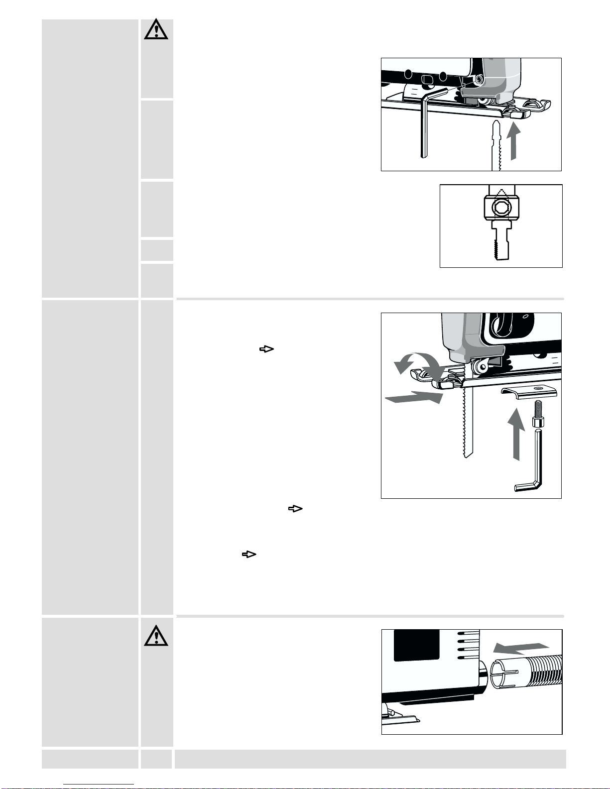
JRissige Sägeblätter oder solche, die ihre Form verändert haben, dürfen nicht
verwendet werden!
Der A-bewertete Schalldruckpegel des Gerätes beträgt typischerweise 82 dB (A).Der
Geräuschpegel beim Arbeiten kann 85 dB (A) überschreiten. Gehörschutz tragen!
Meßwerte ermittelt entsprechend EN 50 144.
Die bewertete Beschleunigung beträgt typischerweise 3 m/s2.
Meßwerte ermittelt entsprechend EN 50 144.
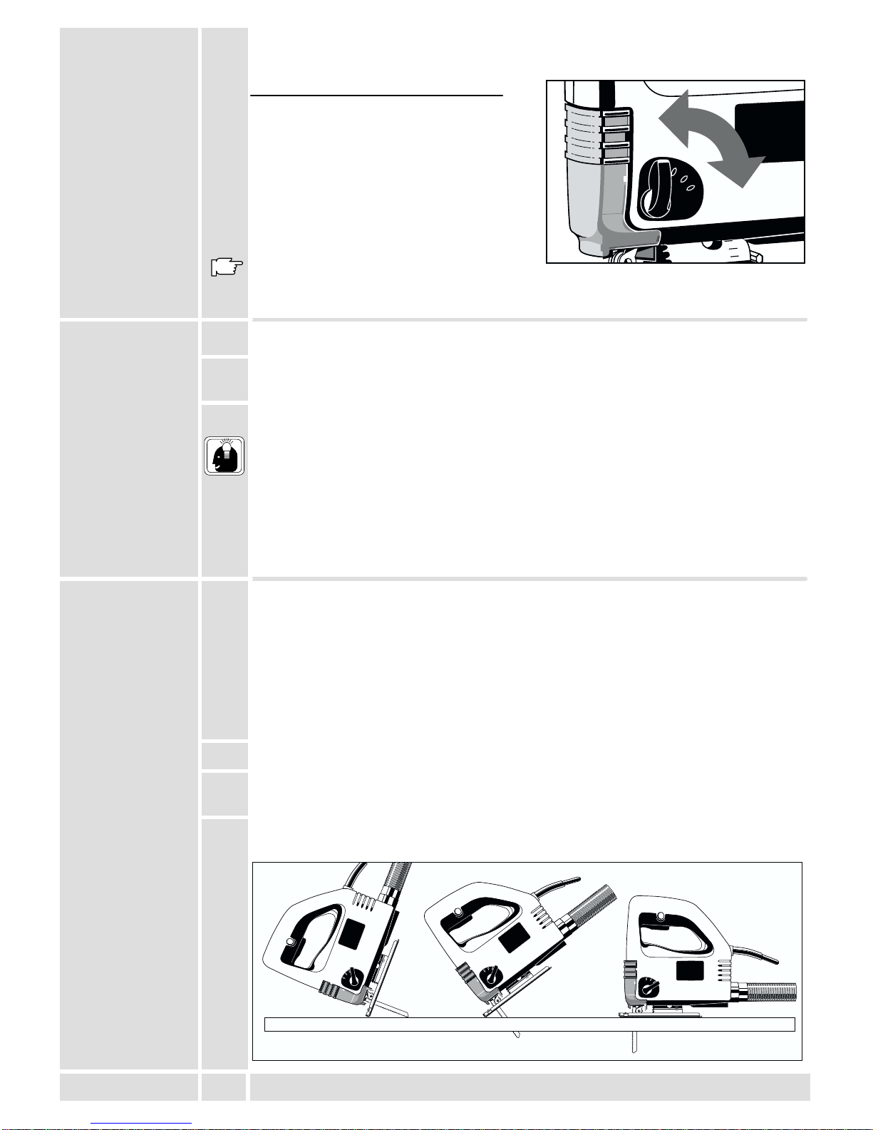
Die Stichsäge sägt Holz, Kunststoff und Metall. Sie schneidet Geraden, Gehrungen,
Kurven und Innenausschnitte.
Dieses Gerät darf nur wie angegeben bestimmungsgemäß verwendet werden.
Nur an Einphasen-Wechselstrom und nur an die auf dem Leistungsschild
angegebene Netzspannung anschließen. Anschlußist auch an Steckdosen ohne
Schutzkontakt möglich, da eine Schutzisolierung nach DIN 57 740/ VDE 0740 bzw.
CEE 20 vorliegt. Die Funkentstörung entspricht der Europanorm EN 55014.
Vorwort
Technische
Daten
Hinweise für
Ihre Sicherheit
Geräusch-
meßwerte
Vibrations-
meßwerte
Verwendung
Netzanschluß

8
DEUTSCH ST 500, STE 500, STEP 500
Kurzbeschreibung
15
0
B
A
III
II
I
0
Änderungen: Text, Bild und Daten entsprechen dem technischen Stand
zur Zeit des Drucktermins. Änderungen im Sinne der Weiterentwicklung
unserer Produkte sind vorbehalten.
Für Dauerschaltung kann der Ein-/Ausschalter
am Arretierknopf festgestellt werden.
Der Ein-/Ausschalter ist so geformt,
daßer in vorderer und hinterer
Griffposition bedient werden kann.
Die Späneblasvorrichtung
bläst den Schnitt von
Spänen frei; sehr
praktisch beim Sägen
nach Anriß.
Integrierter
Absaugkanal zum
Anschlußeiner
Späneabsaugung.
Der Vibrationsausgleich ermöglicht einen
ruhigeren Lauf durch gegenläufige Gewichte
am Stößel.
Verschiebbare
Klarsichtabdeckung
für optimale
Späneabsaugung.
Mit dem Stellrad kann die Hubzahl
(= Bewegung des Sägeblattes pro Minute)
stufenlos reguliert werden.
(nur bei STE 500, STEP 500)
Der Spanreißschutz verhindert
weitgehend das Absplittern an
der Schnittkante bei
Holzbearbeitung. (Zubehör*)
* Im Lieferumfang nicht
enthalten, empfohlene
Ergänzung aus dem
Zubehörprogramm.
Für Schrägschnitte ist die Fußplatte
beidseitig um 45overstellbar, für
Tauchschnitte und randnahes Sägen ist sie
nach hinten versetzbar.
Integrierte Werkzeuggarage für
Zusatzblatt.
Die eingebaute Pendelung erhöht die Schnittleistung.
Durch die Pendelbewegung des Sägeblattes wird
dieses nur beim Rückwärtshub (Arbeitshub) gegen
das Material gedrückt, beim Vorwärtshub jedoch vom
Material abgehoben. Ergebnis: besserer
Spanauswurf, geringere Reibung –> höhere
Schnittleistung.
Am Pendelschalter kann die Pendelung verstellt und
somit den verschiedenen Materialien angepasst
werden. (nur bei STEP 500)

9
DEUTSCH ST 500, STE 500, STEP 500
Vor allen Arbeiten an der Maschine Stecker aus der Steckdose ziehen.
1. Klarsichtabdeckung nach unten schieben,
somit ist die Klemmschraube besser
zugänglich.
2. Klemmschraube mit
Innensechskantschlüssel (an der
Fußplatte angebracht) ca. zwei
Umdrehungen lösen.
3. Sägeblatt in die Nut der Stützrolle legen und bis zum
Anschlag fest in den Stößel einschieben; die Nasen
des Sägeblattes müssen am Stößelbund anschlagen
(siehe Abbildung).
4. Klemmschraube wieder festziehen.
5. Sägeblatt auf festen Sitz kontrollieren
(Schutzhandschuhe tragen!).
Die Fußplatte kann schräggestellt,
verschoben oder versetzt werden.
Schrägstellung Gehrungen
(Schrägschnitte)
Hierzu Feststellschraube lösen, Fußplatte
aus der Rasterung ziehen, im
gewünschten Winkel (15o, 30o, 45o)
einrasten lassen und Feststellschraube
wieder festziehen.
Andere Winkel bis 45osind außerhalb der
Rasterung einstellbar.
Der Winkel kann an Skala abgelesen
werden.
Für sehr genaue Schrägschnitte, zuvor
einen Probeschnitt durchführen.
Verschieben Tauchschnitte mit langem Sägeblatt
Hierzu Feststellschraube lösen, Fußplatte nach hinten schieben und
Feststellschraube wieder festziehen.
In dieser Position ist die Fußplatte in 0o-Stellung fixiert.
Versetzen Tauchschnitte mit kurzem Sägeblatt und randnahes Sägen
Hierzu Feststellschraube herausschrauben, Fußplatte nach hinten versetzen und
Feststellschraube in der hinteren Bohrung festziehen.
Die Fußplatte ist auch in dieser Position in Längsrichtung verschiebbar.
Maschine nur mit einer geeigneten
Späneabsaugung betreiben.
Der integrierte Absaugkanal hat den
genormten Innen-øvon 30 mm.
Zum Anschlußan einen
Haushaltsstaubsauger oder einen Atlas
Copco Naß- und Trockensauger den
Saugschlauch (Id.Nr. 4932 3304 12) aus
dem Zubehörprogramm verwenden.
Einsetzen des
Sägeblattes
Verstellen der
Fußplatte
Späneabsaugung
0
274315
0
15
0

10
DEUTSCH ST 500, STE 500, STEP 500
1. Saugschlauch drehend in den
Absaugkanal stecken bis er festsitzt.
2. Klarsichtabdeckung nach unten schieben,
somit ist eine optimale Staubabsaugung
gegeben.
Der Spanreißschutz verhindert weitgehend
das Absplittern an der Schnittkante bei
Holzbearbeitung.
Den Spanreißschutz wie in Abb. mit der
glatten Seite nach unten bündig auf die
Fußplatte stecken (nur in der vorderen
Fußplattenstellung möglich).
* Im Lieferumfang nicht enthalten,
empfohlene Ergänzung aus dem
Zubehörprogramm.
Mit dem Stellrad kann die Hubzahl
(= Bewegung des Sägeblattes pro Minute)
stufenlos reguliert werden.
Auf dem Stellrad sind die Buchstaben
A ... G aufgedruckt; hierbei gilt:
A = kleinste Hubzahl
G = größte Hubzahl
Die für das zu bearbeitende Material
geeignete Hubzahl der nachfolgenden
Tabelle entnehmen und den
entsprechenden Buchstaben auf dem
Stellrad einstellen.
Material Hubzahl
Holz G
Stahl D-E
Alu D-E
Gummi A-C
Momentschaltung
Einschalten: Ein-/Ausschalter drücken.
Ausschalten: Ein-/Ausschalter loslassen.
Dauerschaltung
Einschalten: Ein-/Ausschalter drücken und
dann Arretierknopf drücken,
Ein-/Ausschalter loslassen.
Ausschalten: Ein-/Ausschalter drücken
und loslassen.
Beim Einstellen der Pendelung wird der Eingriff der Sägeblattzähne in das Material
vergrößert bzw. verkleinert. Als Faustregel gilt:
Weiche Materialien große Pendelung
Harte Materialien kleine Pendelung bzw. keine Pendelung
Saubere Schnittoberfläche keine Pendelung
Spanreißschutz
(Zubehör*)
Einstellen der
Hubzahl
(nur bei
STE 500
STEP 500)
Ein-/Ausschalten
Einstellen der
Pendelung
(nur bei
STEP 500)
III
II
I
0
B
A
B
A
B
A
1
2

11
DEUTSCH ST 500, STE 500, STEP 500
Die geeignete Pendelung der nachfolgenden Tabelle entnehmen und am
Pendelschalter einstellen.
Material Pendelstufe
Holz I - III
Kunststoff I
Alu 0 - I
Stahl 0
Keramik 0
Gummi 0
Die in der Tabelle vorgeschlagenen
Pendelstufen sind nur Anhaltswerte.
Das Einstellen der Pendelung am
Pendelschalter läßt sich auch bei
laufender Maschine vornehmen.
1. Hubzahl und Pendelung entsprechend dem zu bearbeitenden Material einstellen
2. Maschine mit dem vorderen Teil der Fußplatte auf das Material aufsetzen und
einschalten.
3. Die Maschine von oben auf das Material drücken und entlang der Schnittlinie
führen.
Nicht zuviel Schnittdruck geben. Ein leichter Druck auf das Sägeblatt genügt um
einen optimalen Sägefortschritt zu erzielen.
Bei Sägen nach Anrißdie Markierung im Spanreißschutz als Orientierungshilfe
verwenden.
Für exakt gerade Schnitte, eine Leiste als Anschlag auf das Material klemmen oder
Parallelanschlag (Zubehör) verwenden.
Für Gehrungsschnitte (Schrägschnitte) die Fußplatte verstellen.
Für randnahes Sägen die Fußplatte in die hinterste Stellung versetzen.
Um ein Mitfedern zu vermeiden, Bleche auf einer Holzunterlage festspannen. Beim
Metallsägen entlang der Schnittlinie Kühlmittel (Öl, Petroleum) auftragen.
Tauchsägen ist nur in weicheren Materialien (Holz, Leichtbaustoffe für Wände)
möglich, bei härteren Materialien (Metalle) mußeine dem Sägeblatt entsprechend
große Bohrung angebracht werden.
Um einen günstigen Schnittwinkel zum Einstechen zu erhalten, die Fußplatte in die
hinterste Stellung versetzen.(siehe Kap. ”Verstellen der Fußplatte”)
1. Pendelung am Pendelschalter auf “0”stellen.
2. Maschine ausgeschaltet mit der vorderen Kante der Fußplatte auf die Schnittstelle
aufsetzen.
3. Maschine einschalten und Sägeblatt vorsichtig sägend in das Material eintauchen.
GERMANY
274315
STEP 500
electronic
III
II
I
0
GERMANY
274315
STEP 500
electronic
III
II
I
0
GERMANY
274315
STEP 500
electronic
III
II
I
0
Arbeitshinweise
Tips
Sägen von
Blechen
Herstellen
von Innenaus-
schnitten
15
0
III
II
I
0

12
DEUTSCH ST 500, STE 500, STEP 500
Mit Hilfe des Parallelanschlags mit Kreisführung sind Parallelschnitte von 0 - 200 mm
und Kreisschnitte von 100 - 400 mm möglich.
Geschränkte Sägeblätter verwenden.
* Im Lieferumfang nicht enthalten, empfohlene Ergänzung aus dem
Zubehörprogramm.
Den Parallelanschlag mit der
Anschlagfläche nach unten durch die
Laschen in der Fußplatte schieben und mit
der Knebelschraube befestigen
Für links bzw. rechts angeschlagene
Schnitte den Parallelanschlag von der
entsprechenden Seite einschieben.
Den Parallelanschlag mit der
Anschlagfläche nach oben durch die
Laschen in der Fußplatte schieben und
mit der Knebelschraube befestigen.
Die Kreisführung von oben in den
Parallelanschlag einschrauben.
Darauf achten, daßSägeblatt und
Kreisführung eine Linie bilden.
Bei empfindlichen Oberflächen sollte der Kunststoffgleitschuh verwendet werden.
* Im Lieferumfang nicht enthalten, empfohlene Ergänzung aus dem
Zubehörprogramm.
Den Kunststoffgleitschuh vorn in die
Fußplatte einhängen und dann die Zungen
im hinteren Teil in die Fußplatte einrasten.
Beide Zungen nach außen biegen und
Kunststoffgleitschuh abnehmen.
Weiteres Zubehör mit den Bestellnummern
ersehen Sie bitte aus unseren Katalogen.
Um eine ständige Betriebsbereitschaft zu gewährleisten, sollte die Maschine einmal
jährlich auf abgenutzte Kohlebürsten in einem AEG-Kundendienststützpunkt
untersucht werden.
Nur AEG Zubehör und Ersatzteile verwenden. Bauteile, deren Austausch nicht
beschrieben wurde, bei einer AEG Kundendienststelle auswechseln lassen
(Broschüre Garantie/Kundendienstadressen beachten).
Bei Bedarf kann eine Explosionszeichnung des Gerätes unter Angabe der
Maschinen Type und der zehnstelligen Nummer auf dem Leistungsschild bei Ihrer
Kundendienststelle oder direkt bei Atlas Copco Electric Tools GmbH, Postfach 320,
D–71361 Winnenden angefordert werden.
Parallelanschlag
mit Kreisführung
(Zubehör*)
Verwendung als
Parallelanschlag
Verwendung als
Kreisführung
Kunststoffgleit-
schuh (Zubehör*)
Montage
Demontage
Wartung
GERMANY
274315
GERMANY
274315
GERMANY
274315
15
0

13
FRANÇAIS ST 500, STE 500, STEP 500
Vous exigez ce qu’il y a de meilleur et vous achetez de la qualité–la qualitéofferte
par Atlas Copco. Vous vous êtes dotés d’un outil de qualitédurable. Ce n’est qu’en
lisant attentivement ces instructions avant d’utiliser l’outil que vous assurerez un
travail efficace et sans risque. Nous tenons àsatisfaire notre clientèle et nous
espérons que vous achèterez encore desoutils électriques AEG d’Atlas Copco.
ST 500 STE 500 STEP 500
Profondeur de coupe max.:
Bois tendre 65 mm 70 mm 70 mm. . . . . . . . . . . . . . . . . . . . . . . . . . . . . . . . . .
Bois 55 mm 60 mm 60 mm. . . . . . . . . . . . . . . . . . . . . . . . . . . . . . . . . . . . . . . .
Acier 5 mm 5 mm 5 mm. . . . . . . . . . . . . . . . . . . . . . . . . . . . . . . . . . . . . . . . . .
Aluminium 10mm 10mm 10mm. . . . . . . . . . . . . . . . . . . . . . . . . . . . . . . . . . .
Puissance absorbée 500 W 500 W 500 W. . . . . . . . . . . . . . . . . . . . . . . . . . .
Poids 1,9 kg 1,9 kg 1,9 kg. . . . . . . . . . . . . . . . . . . . . . . . . . . . . . . . . . . . . . . . . .
Nombre de courses àvide 3000 min-1 450-3000 min-1 450-3000 min-1
. . . . . . .
Hauteur de la course 19 mm 19 mm 19 mm. . . . . . . . . . . . . . . . . . . . . . . . . . .
Coupe de biais jusqu’à 45o45o45o
. . . . . . . . . . . . . . . . . . . . . . . . . . . . . .
JRespecter les instructions de sécuritése trouvant dans le prospectus ci-joint.
JLa poussière qui se dégage lors de l’usinage des matériaux contenant de l’amiante
et des pierres contenant de l’acide silicique cristallin porte atteinte àla santé.
JLes prises de courant se trouvant àl’extérieur doivent être équipées de disjoncteurs
de protection, répondant ainsi àla prescription de mise en place de votre installation
électrique. Veuillez, d’une part, en tenir compte lors de l’utilisation de notre appareil
et d’autre part, en parler àvotre électricien.
JIl est absolument impératif d’utiliser le dispositif protecteur de la machine.
JAvant tous travaux sur la machine extraire la fiche de la prise de courant.
JToujours porter des lunettes protectrices lorsqu’on travaille avec la machine. Des
gants de sécuritéet un masque de protection sont recommandés.
JNe jamais enlever les copeaux ni les éclats lorsque la machine est en marche.
JNe pas percer le carter de la machine; ceci pourrait entraîner une détérioration de
l’isolation de protection (utiliser des autocollants).
JLe câble d’alimentation doit toujours se trouver en dehors du champ d’action de la
machine. Toujours maintenir le câble d’alimentation àl’arrière de la machine.
JNe raccorder la machine au réseau que si l’interrupteur est en position arrêt.
JLors de travaux de ponçage de longue durée, sur du bois ou autres matériaux
dégageant de la poussière nocive pour la santé, la machine doit être raccordée àun
appareil d’aspiration.
JNe pas utiliser de lames de scie fissurées ou déformées.
La mesure réelle (A) du niveau de bruit de l’outil est 82 dB (A).Le niveau du briut en
fonctionement peut dépasser 85 dB (A). Toujours porter des casques protecteurs!
Valeurs de mesures obtenues conformément àla norme européenne 50 144.
L’accélération réelle mesurée est 3 m/s2.
Valeurs de mesures obtenues conformément àla norme européenne 50 144.
La scie sauteuse coupe le bois, la matière synthétique et le métal. Elle permet les
coupes droites, de biais, de courbes et de découpes intérieures.
Comme déjàindiqué, cette machine n’est conçue que pour une utilisation normale.
Nos machines fonctionnent uniquement sur courant alternatif monophasé. S’assurer
que la tension du réseau correspond effectivement àcelle indiquée sur la plaque
signalétique de la machine. Le branchement sur une prise de courant sans mise à
terre est possible du fait de la double isolation selon normes DIN 57 740/VDE 0740
et CEE 20. Antiparasitage selon normes européennes EN 55014.
Introduction
Caractéristiques
techniques
Conseils de
sécurité
Mesure de bruit
Valeur de
vibration
mesurée
Utilisation
Branchement
secteur

14
FRANÇAIS ST 500, STE 500, STEP 500
Description
15
0
B
A
III
II
I
0
Modifications: Les textes, les illustrations et les données techniques
correspondent àla situation au moment de l’impression. Toutes
modifications techniques sont réservées dans le cadre du développement
technique permanent.
En marche continue, l’interrupteur de
marche/arrêt peut être maintenu en position au
moyen de blocage.
La forme de l’interrupteur de
marche/arrêt est telle, qu’il peut être
utiliséen position avant ou arrière de la
poignée.
Le dispositif d’aspiration
des copeaux dégage la
coupe, ce qui est
particulièrement
appréciable lors du sciage
devant être effectuéselon
un tracé.
Canal d’aspiration
intégrépour le
raccordement d’un
dispositif d’aspiration
des copeaux.
La compensation des vibrations se traduit par
une coupe très calme grâce aux contrepoids
antagonistes au niveau du coulisseau.
Capot transparent
décalable, prévu
pour l’aspiration
optimale des
copeaux.
Le bouton de réglage permet de régler sans
à–coups le nombre de courses (nombre de
mouvements effectués par la lame de scie en
une minute).
(uniquement sur STE 500, STEP 500)
Le pare-éclats réduit
considérablement les éclats sur les
bords de coupe lors du sciage du
bois. (accessoire*)
*Ces pièces ne font pas partie de la
livraison. Il s’agit làde compléments
proposés pour votre machine et
énumérés dans le catalogue
d’accessoires.
Afin de permettre la réalisation d’une
coupe de biais, la semelle doit être inclinée
des deux côtés à45o. Elle doit être
décalée vers l’arrière lorsqu’on désire
effectuer des coupes en plongée et un
sciage àproximitédes bords.
Logement pour une lame de
scie additionnelle.
Le mécanisme pendulaire intégréaugmente le
rendement de coupe. Du fait de son mouvement
pendulaire, la lame de scie n’est pressée contre le
matériau qu’au moment du déplacement vers
l’arrière (course de travail) et elle est soulevée du
matériau pendant le déplacement vers l’avant.
Résultat: meilleure éjection des copeaux, diminution
du frottement –> augmentation de la performance de
coupe.
Le mouvement pendulaire peut être régléau moyen
du commutateur ce qui permet de l’adapter aux
différents matériaux. (uniquement sur STEP 500)

15
FRANÇAIS ST 500, STE 500, STEP 500
Avant tous travaux sur la machine extraire la fiche de la prise de courant.
1. Pousser le capot transparent vers le bas,
afin d’accéder plus facilement àla vis de
blocage.
2. Desserrer d’environ 2 tours la vis de
blocage au moyen de la cléhexagonale
intérieure placée au niveau de la semelle.
3. Placer la lame de scie dans la fente du galet d’appui et
l’introduire dans le coulisseau jusqu’à concurrence de
sa butée; les deux épaulements de la lame de scie
doivent venir en contact avec le collet du coulisseau
(voir figure).
4. Resserrer la vis de blocage.
5. Vérifier le positionnement correct de la lame de scie
(ne pas oublier de porter des gants de protection!).
La semelle peut être inclinée, repoussée
ou décalée.
Inclinaison coupes inclinées (coupe
de biais).
Pour ce faire, desserrer la vis de réglage,
sortir la semelle du cran, l’encranter à
l’angle souhaité(15o, 30o, 45o) et
resserrer la vis de réglage. Les autres
angles sont réglables en dehors de la
plage d’encrantement. L’angle peut être lu
sur le cadran.
Pour les coupes de biais précises,
exécuter préalablement un coupe d’essai.
Repoussement coupes en plongée
avec longue lame de scie.
Pour ce faire, desserrer la vis de réglage, repousser la semelle vers l’arrière et
resserrer la vis de réglage. Dans cette position, la semelle est fixée en position 0o.
Décalage coupes en plongée avec courte lame de scie et coupes àproximité
des bords.
Pour ce faire, desserrer la vis de réglage, décaler la semelle vers l’arrière et serrer
la vis de réglage dans le trou arrière. Dans cette position, la semelle est également
décalable en sens longitudinal.
N’utiliser la machine qu’en liaison avec un
dispositif d’aspiration appropriédes
copeaux.
Le øintérieur normalisédu canal
d’aspiration intégréest de 30 mm.
Pour permettre le branchement sur un
aspirateur ménager ou un aspirateur à
sec/liquide Atlas Copco, utiliser le tuyau
d’aspiration Atlas Copco (Nº
4932 3304 12) faisant partie du
programme d’accessoires.
Mise en place de
la lame de scie
Réglage de la
semelle
Aspiration des
copeaux
0
274315
0
15
0

16
FRANÇAIS ST 500, STE 500, STEP 500
1. Introduire intégralement le tuyau
d’aspiration dans le canal en lui appliquant
un mouvement de rotation.
2. Pousser le capot transparent vers le bas,
afin d’obtenir une aspiration optimale de la
sciure.
Le pare-éclats réduit considérablement les
éclats sur les bords de coupe lors du
sciage du bois.
Introduire le pare-éclats sur la semelle
comme le montre la figure, c’est-à- dire
côtélisse vers le bas (possible
uniquement en position avant de la
semelle).
*Ces pièces ne font pas partie de la livraison. Il s’agit làde compléments proposés
pour votre machine et énumérés dans le catalogue d’accessoires.
Le bouton de réglage permet de régler
sans à–coups le nombre de courses
(nombre de mouvements effectués par la
lame de scie en une minute).
Le bouton de réglage porte les lettres A ...
G qui signifient:
A = Nombre de courses le plus faible
G = Nombre de courses le plus élevé
Le régime des courses, appropriéau
matériau àusiner, est spécifiésur le
tableau suivant. Il vous suffit d’ajuster la
lettre correspondante sur le bouton de
réglage.
Matériau àscier Nombre de courses
Bois G
Acier D-E
Aluminium D-E
Caoutchouc A-C
Marche momentanée
Mise en marche: appuyer sur l’interrupteur
Marche/Arrêt
Arrêt: lâcher l’interrupteur Marche/Arrêt
Marche continue
Mise en marche: appuyer d’abord sur
l’interrupteur marche/arrêt puis sur le
bouton de blocage, lâcher l’interrupteur
marche/arrêt.
Arrêt: appuyer sur l’interrupteur
marche/arrêt et lâcher.
Lors du réglage du mouvement pendulaire, la pénétration des dents de la lame de
scie est augmentée ou diminuée. Règle approximative applicable:
Matériaux tendres Grand mouvement pendulaire
Matériaux durs Petit mouvement pendulaire ou pas de
mouvement pendulaire Surface de coupe
soignée Pas de mouvement pendulaire
Pare-éclats
(accessoire*)
Réglage du
nombre de
courses
(uniquement sur
STE 500
STEP 500)
Mise en
marche/arrêt
Réglage du
mouvement
pendulaire
(uniquement sur
STEP 500)
III
II
I
0
B
A
B
A
B
A
1
2

17
FRANÇAIS ST 500, STE 500, STEP 500
Les mouvements pendulaires appropriés sont indiqués sur le tableau ci-dessous et
se règlent au moyen du commutateur pendulaire.
Matériau Degrépendulaire
Bois I - III
Matière synthétique I
Aluminium 0 - I
Acier 0
Céramique 0
Caoutchouc 0
Les degrés pendulaires proposés sur le
tableau ne sont bien entendu que des
valeurs indicatives et approximatives!
Le réglage pendulaire au moyen du
commutateur peut tout aussi avoir lieu
lorsque la machine est en marche.
1. Régler le nombre de courses et mouvements pendulaires en fonction du matériau
àscier.
2. Appliquer la partie avant de la semelle sur le matériau àscier et brancher la
machine.
3. Appuyer la machine sur le matériau àscier (pression appliquée du haut) et la
guider le long de la ligne de coupe.
Ne pas excercer une pression de coupe excessive. Une pression légère sur la lame
de scie est amplement suffisante pour garantir une progression optimale de la scie.
Lorsque l’on doit scier selon un tracé, se servir du repère placésur le pare-éclats
afin de faciliter l’orientation.
Afin d’assurer une coupe rectiligne, fixer une barrette sur le matériau pour faire office
de butée ou encore, utiliser une butée parallèle (accessoire).
Lorsqu’on doit effectuer des coupes inclinées (coupes de biais), il convient alors de
décaler la semelle.
S’il s’agit de scier àproximitédes bords, amener la semelle dans la position la plus
arrière.
Afin d’éviter l’effet de ressort, fixer les tôles sur un morceau de bois. Si l’on doit scier
du métal, utiliser un liquide réfrigérant le long de la ligne de coupe (huile, pétrole).
Le sciage en plongée n’est possible que dans des matériaux tendres (bois,
matériaux de construction légers pour les murs). Si les matériaux sont plus durs
(métaux), une percée plus importante doit être faite au moyen de la lame.
Afin d’obtenir un angle de coupe favorable pour le sciage en plongée, déplacer la
semelle dans sa position la plus arrière.(voir chapitre ”Réglage de la semelle”)
1. Le mouvement pendulaire doit être amenésur ”0”sur le commutateur sélecteur.
2. Le bord avant de la semelle doit être placésur le point de coupe, alors que la
machine est débranchée.
3. Brancher la machine et introduire la lame prudemment dans le matériau.
GERMANY
274315
STEP 500
electronic
III
II
I
0
GERMANY
274315
STEP 500
electronic
III
II
I
0
GERMANY
274315
STEP 500
electronic
III
II
I
0
Conseils
pratiques
Conseils
Sciage de tôles
Réalisation de
découpes
intérieures
15
0
III
II
I
0

18
FRANÇAIS ST 500, STE 500, STEP 500
A l’aide du guide parallèle et circulaire, on peut réaliser des coupes parallèles de 0 -
200 mm et circulaires de 100 - 400 mm. Utiliser des lames de scie sauteuse
avoyées.
*Ces pièces ne font pas partie de la livraison. Il s’agit làde compléments proposés
pour votre machine et énumérés dans le catalogue d’accessoires.
La face d’arrêt de la butée parallèle doit
être introduite (orientée vers le bas) dans
l’éclisse de la semelle et être fixée au
moyen de la vis àgarret.
La butée parallèle doit être introduite du
côtécorrespondant pour permettre les
coupes àgauche ou àdroite.
La face d’arrêt de la butée parallèle doit
être introduite (orientée vers le bas) dans
l’éclisse de la semelle et être fixée au
moyen de la vis àgarret.
Visser le guidage circulaire dans la butée
parallèle.
Veiller àce que la lame de scie forme une
seule ligne avec le guidage circulaire,
c’est-à-dire, que cet ensemble soit en
alignement.
Pour des surfaces sensibles utiliser le patin de crosse en matière plastique.
*Ces pièces ne font pas partie de la livraison. Il s’agit làde compléments proposés
pour votre machine et énumérés dans le catalogue d’accessoires.
Monter le patin de crosse en matière
plastique devant, puis faire encliqueter les
languettes dans le plateau de base
derrière.
Plier les deux languettes vers l’extérieur et
enlever le patin de crosse en matière
plastique.
Pour d’autres accessoires, consulter notre
catalogue.
Afin de garantir une disponibilitéde service permanente, il est recommandéde faire
contrôler une fois par an les balais (charbons) auprès d’un service après–vente
AEG.
N’utiliser que des pièces et accessoires AEG. Pour des pièces dont l’échange n’est
pas décrit, s’adresser de préférence aux stations de service après-vente AEG (voir
brochure Garantie/Adresses des stations de service après-vente).
Si besoin est, une vue éclatée de l’appareil peut être fournie. S’adresser, en
indiquant bien le numéro àdix chiffres portésur la plaque signalétique, àvotre
station de service après–vente (voir liste jointe) ou directement àAtlas Copco
Electric Tools GmbH, B.P. 320, D–71361 Winnenden.
Butée parallèle
avec guidage
circulaire
(accessoire*)
Utilisation en tant
que butée
parallèle
Utilisation en tant
que guidage
circulaire
Patin en matière
synthétique
(accessoire*)
Montage
Démontage
Entretien
GERMANY
274315
GERMANY
274315
GERMANY
274315
15
0

19
ITALIANO ST 500, STE 500, STEP 500
Lei èdecisamente esigente e per questa ragione acquista solo prodotti di qualità.
Qualitàche la Atlas Copco èperfettamente in grado di garantirLe. Abbiamo
realizzato proprio per Lei un utensile che sia il piùpossibile affidabile e sicuro. Ora
tocca a Lei. Perchèanche il Suo lavoro sia sicuro e di ottima qualità, La preghiamo
di voler leggere attentamente le istruzioni per l’uso. E’nostro desiderio, infatti, che
anche in futuro acquisti utensili elettrici AEG della Atlas Copco.
ST 500 STE 500 STEP 500
Massima profonditàdi taglio nel:
Legno tenero 65 mm 70 mm 70 mm. . . . . . . . . . . . . . . . . . . . . . . . . . . . . . . .
Legno 55 mm 60 mm 60 mm. . . . . . . . . . . . . . . . . . . . . . . . . . . . . . . . . . . . . .
Acciaio 5 mm 5 mm 5 mm. . . . . . . . . . . . . . . . . . . . . . . . . . . . . . . . . . . . . . . .
Alluminio 10 mm 10 mm 10 mm. . . . . . . . . . . . . . . . . . . . . . . . . . . . . . . . . . . .
Potenza assorbita 500 W 500 W 500 W. . . . . . . . . . . . . . . . . . . . . . . . . . . . .
Peso 1,9 kg 1,9 kg 1,9 kg. . . . . . . . . . . . . . . . . . . . . . . . . . . . . . . . . . . . . . . . . .
Numero di corse a vuoto 3000 min-1 450-3000 min-1 450-3000 min-1
. . . . . . . .
Altezza corsa 19 mm 19 mm 19 mm. . . . . . . . . . . . . . . . . . . . . . . . . . . . . . . .
Tagli obliqui fino a 45o45o45o
. . . . . . . . . . . . . . . . . . . . . . . . . . . . . . . . . .
JSi prega di leggere con attenzione le istruzioni riguardanti la sicurezza, nel volantino
allegato.
JTenere presente che la polvere che si solleva durante la lavorazione di materiali con
amianto, pietra silice cristallizzata, édannosa alla salute. Attenersi sempre alle
prescrizioni di sicurezza vigenti in materia.
JGli apparecchi mobili usati all’aperto devono essere collegati interponendo un
interruttore di sicurezza per guasti di corrente.
JUsare sempre il dispositivo di protezione dell’apparecchio.
JPrima di effettuare qualsiasi lavoro sulla macchina togliere la spina dalla presa di
corrente.
JDurante l’uso dell’apparecchio utilizzare sempre gli occhiali di protezione. Inoltre si
consiglia di usare sistemi di protezione per la respirazione e per l’udito, oltre ai guanti
di protezione.
JNon rimuovere trucioli o schegge mentre l’utensile èin funzione.
JEvitare di forare la carcassa dell’utensile per non danneggiare l’isolamento.
(Utilizzare placchette adesive).
JTenere sempre lontano il cavo di collegamento dall’area di lavoro dell’attrezzo.
JInserire la spina solo con interruttore su posizione “OFF”.
JPer lunghe lavorazioni nel legno o con altri materiali che producono poveri dannose
alla salute, e’prescritto l’utilizzo sull’utensile dell’aspirazione polvere.
JNon devono essere utilizzate nèlame incrinate nèlame la cui forma abbia subito
alterazioni.
La misurazione A della pressione del livello sonoro di un utensile di solito deve
essere 82 dB (A).Il livello di rumorositàdurante le lavorazioni puòsuperare gli
85 dB (A). Utilizzare le protezioni per l’udito!
Valori misurati conformemente alla norma EN 50 144.
La misurazione dell’accellerazione di solito è3 m/s2.
Valori misurati conformemente alla norma EN 50 144.
Questo seghetto alternativo puòessere utilizzato per lavorare legno, materiale
sintetico e acciaio: per effettuare tagli diritti e obliqui, curve e per tagli all ’interno del
materiale.
Utilizzare il prodotto solo per l’uso per cui èprevisto.
Alimentazione dell’utensile: corrente alternata monofase. Importante: la tensione
della rete deve corrispondere a quella riportata sulla targhetta dell’utensile. Il
collegamento épossibile anche con prese non munite di contatto di protezione: é
previsto infatti un isolamento di protezione conforme a norme DIN 57740/VDE 0740
(CEE 20). La schermatura contro i radiodisturbi éconforme alla norma
europea EN 55014.
Premessa
Dati tecnici
Norme di
sicurezza
Livello di
rumorosità
Livello di
vibrazione
Possibilità’ di
utilizzo
Collegamento
alla rete
This manual suits for next models
10
Table of contents
Languages:
Other AEG Power Tools manuals