Contents
Introduction.23
Extractor
version.
2
3
Filter
version.
2
4
Electrical
connections.25
Safety
warnings
fcfr
electrician.25
Specifications.26
Montage.
2
7
Safety
warnings
for
kitchen
unit
installer.27
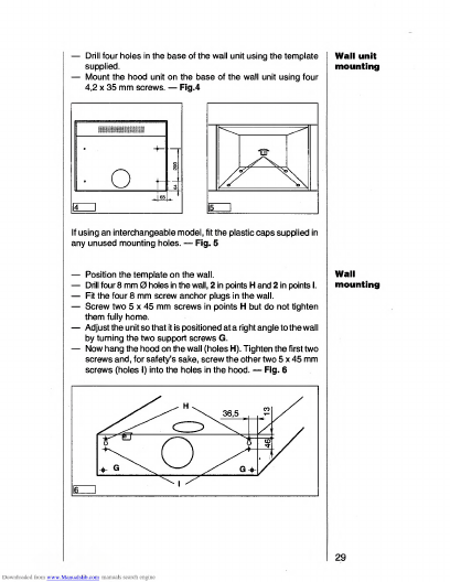
Wall
unit
mounting.29
Wall
mounting.29
Safety
warnings
for
user.30
Hood
operation.31
Controls..31
Setting
the
fan
speed.
3
2
Hood
lighting.32
Intensive
P.33
Fan
timer.33
Switching
off
the
fan
3
4
Hood
operation
before
and
after
cooking.
3
5
Warnings
on
the
activated
carbon
filter.
3
5
Display
warning
on
saturation
of
activated
carbon
filter....35
-
37
Display
warning
on
saturation
of
metal
grease
filters
.38
-
39
Changing
the
light
bulbs
..
.....40
Cleaning...****.,,......,....40
Special
Accessories...
4
1
Technical
Assistance
Service
..
...............
4
1
22
Printed
on
recycled
paper.
AEG
-
putting
words
into
action.