AEM Dryflow Quick start guide
AEM Induction Systems 1 (800) 992-3000 WWW: http://www.aemintakes.com
Equipped with AEM®Dryflow™ Filter
No Oil Required!
INSTALLATION INSTRUCTIONS
PART NUMBER: 21-447
1998-2001 CHEVROLET Cavalier L4-2.2L Manual trans. Requires 20-455 C.A.R.B. E.O. # D-670-6
2000-2002 PONTIAC Sunfire L4-2.2L Manual trans. Requires 20-455 C.A.R.B. E.O. # D-670-6
The installation of this AEM®intake system on manual transmission model year vehicles will also require
the installation of the AEM® clutch reservoir bracket, part # 20-445. The clutch reservoir bracket is
necessary as it is needed to properly support the clutch fluid reservoir.
* NOTE: Legal in California only for racing vehicles which may never be used upon a highway

2
PARTS LIST
Description
Qty.
Part Number
Element Parts Kit 2.75 X 5" Dry Ele.
1
21-202DK
Lower Pipe
1
2-552
Upper Pipe
1
2-553
Hose, Silicone 2.75x3" Blk.
1
5-275
Hose, Hump 2.75/2.75x3.00"
1
5-575
Hose; 1/2"ID X 12"L
1
5-5012
Mount, Rubber 5/8" X 6mm
1
1228598
Grommet, 1/2"
1
784634
Zip Tie,8" Tree Push-Mnt.
2
1-127
Spacer, 1.00 OD X .250 ID X .6
1
2-647
Neoprene, 1/16" X 6" X 1" Adhes.
1
8-121-1
Bolt, Hex M6-1 X 35mm
1
1-2002
Washer; 1"D X 1/4 Hole Fender
4
08160
Nut, M6 Hex Serrated
3
444.460.04
1/2" Bnd. Hose Clamp, 2.31-3.25"
4
9444
Hose Clamp, 3/4"
2
4093-5
1/2" Bnd. Hose Clamp,2.56"-3.50"
1
9448

3
Read and understand these instructions BEFORE attempting to install this product.
Failure to follow installation instructions and not using the provided hardware may
damage the intake tube, throttle body and engine.
The AEM®intake system is a performance product that can be used safely during mild
weather conditions. During harsh and inclement weather conditions, you must return
your vehicle to stock OEM air box and intake tract configuration. Failure to follow these
instructions will void your warranty.
1. Preparing Vehicle
a.Make sure vehicle is parked on level surface.
b.Set parking brake.
c. If engine has run in the past two hours, let it cool down.
d.Disconnect negative battery terminal.
e.Raise the front of the vehicle with a jack. Refer to your owner’s manual for proper jack and jack stand
placement to properly support vehicle. Support your vehicle using properly rated jack stands before wheel
removal or while working under the vehicle.
NEVER WORK UNDER A VEHICLE WITHOUT USING JACK STANDS.
f. Remove front driver side wheel.
g.Do not discard stock components after removal of the factory system.
2. Removal of stock system
a. Factory air box system installed.
b. Release the clip on top of the inlet pipe.

4
c. Loosen the hose clamp at the air box.
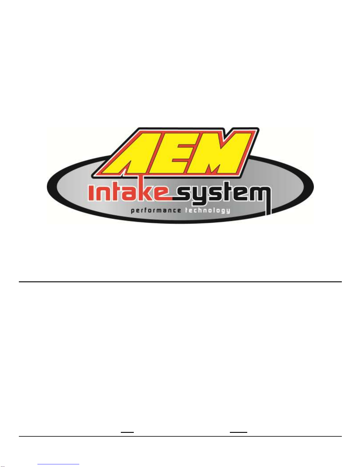
d. Remove bolt. Release the breather hose from the
valve cover.
e. Loosen the hose clamp at the throttle body.
f. Gently pull the inlet air temperature (IAT) sensor from
the inlet pipe. Remove the upper air box from the
vehicle.
NOTE: Do not pull by wires.
5
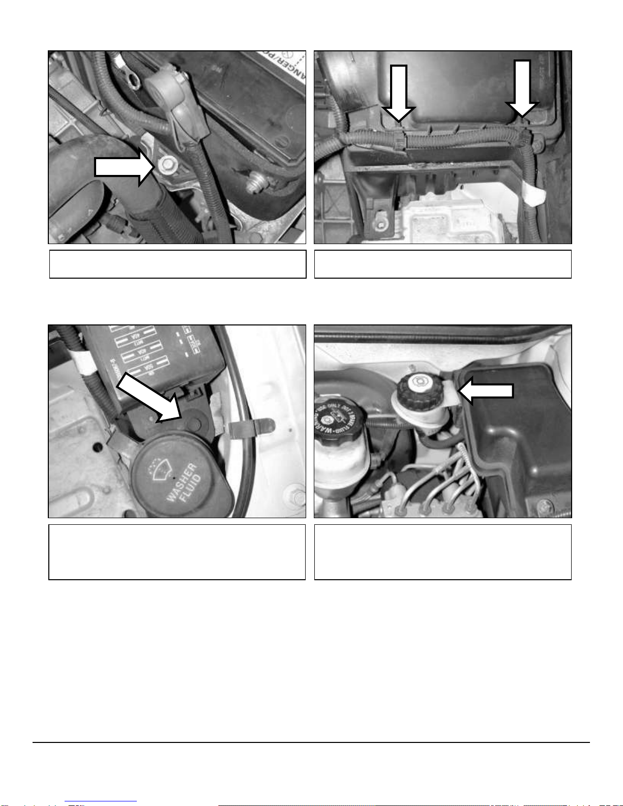
g. Remove the battery by first releasing the tie down
bolt.
h. Release the two wire clips on the air box.
i. Remove the plastic clip that secures the fuse block.
j. If equipped with a manual transmission, remove the
clutch fluid reservoir from the air box. Secure it to the
firewall with AEM®part # 20-445 (sold separately).
Remove the air box from the vehicle.

6
l. Release the two wire clamps on the back of the
washer fluid bottle.
k. Remove the left fender liner to expose the lower air
box / washer bottle assembly.
m. Unplug the washer motor. Pull the washer fluid
hose off of the motor and drain the fluid into a clean
suitable container.
n. Remove the bolt that secures the washer bottle to
the fender.
7
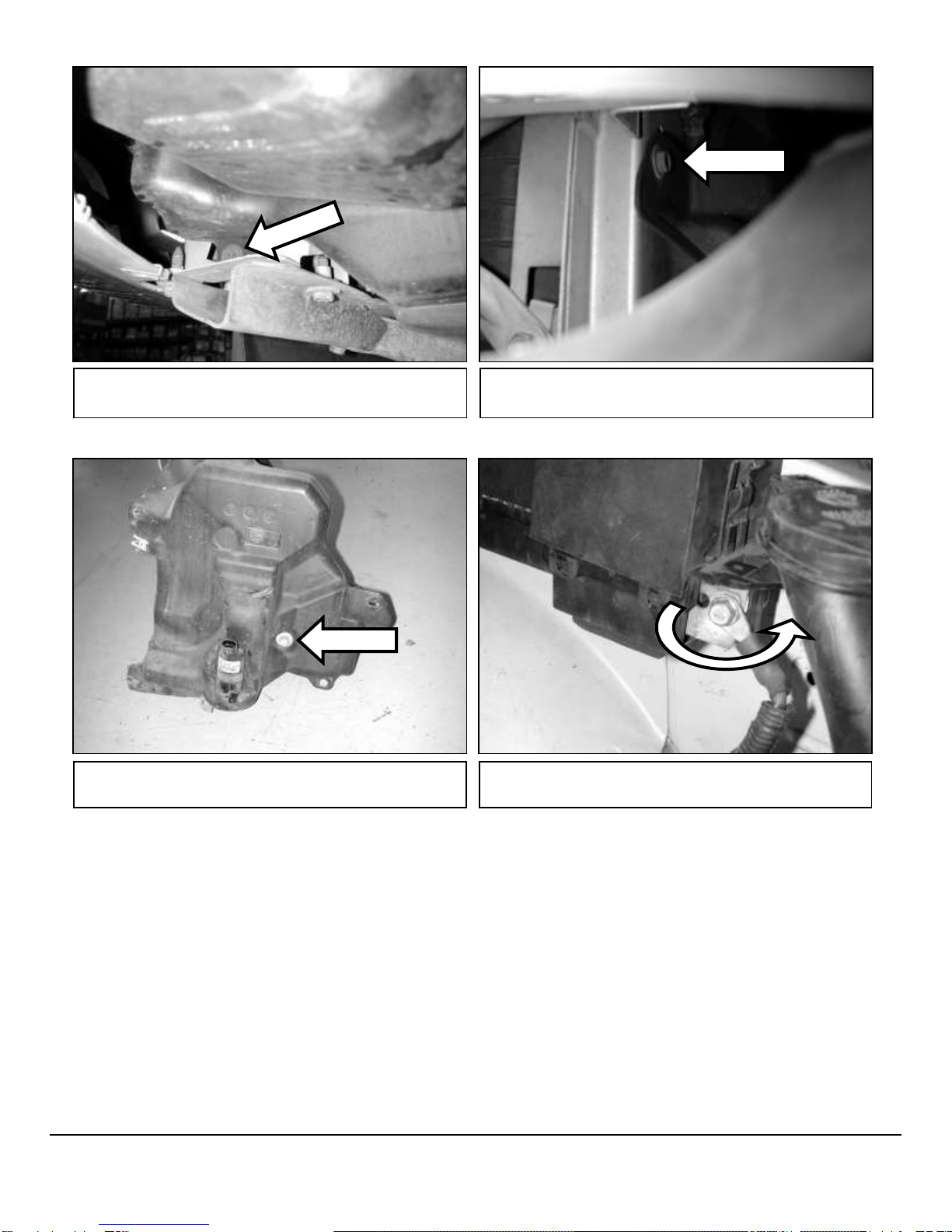
p. Remove the upper bolt near the front of the washer
bottle. This picture was taken through the front grill.
q. Remove the washer bottle from the vehicle. Loosen
the bolt connecting the bottle to the lower air box.
r. Loosen the positive lead on the fuse block. Rotate it
as shown. Tighten the lead.
o. Remove the lower bolt near the front of the washer
bottle.
8
3. Installation of AEM®intake system.
a.When installing the intake system, do not completely tighten the hose clamps or mounting hardware until
instructed to do so.
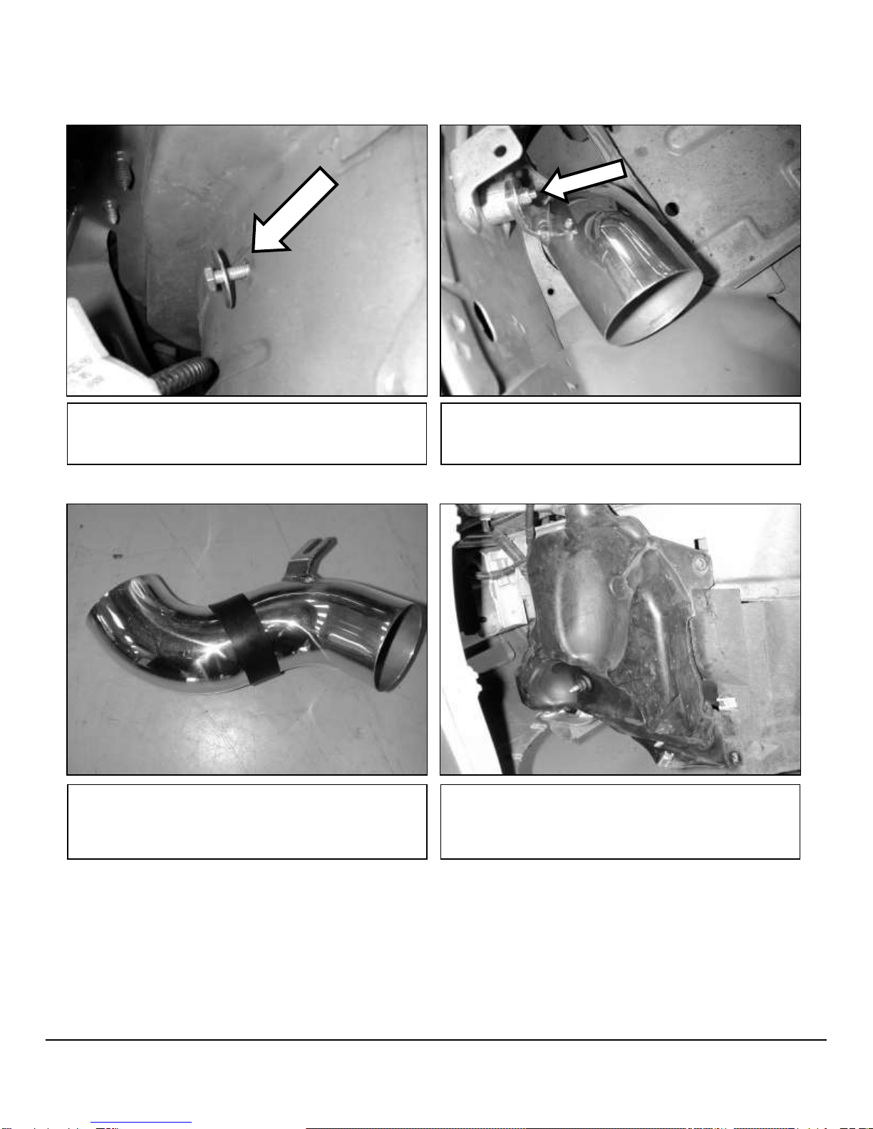
b. Install supplied bolt and washer through fender as
shown. This picture was taken from inside the fender
well.
c. Install spacer as shown. Install the lower pipe in the
engine bay. Center the pipe in the hole in the fender
and tighten the nut on the spacer.
Mark pipe here.
And here.
e. Reinstall the washer bottle without the lower air box.
Reattach the washer fluid hose and plug in the washer
motor.
d. Mark the pipe approximately ½” above and below
the hole in the fender. Remove the pipe and apply the
adhesive neoprene material as shown. Reinstall the
intake pipe as previously directed.

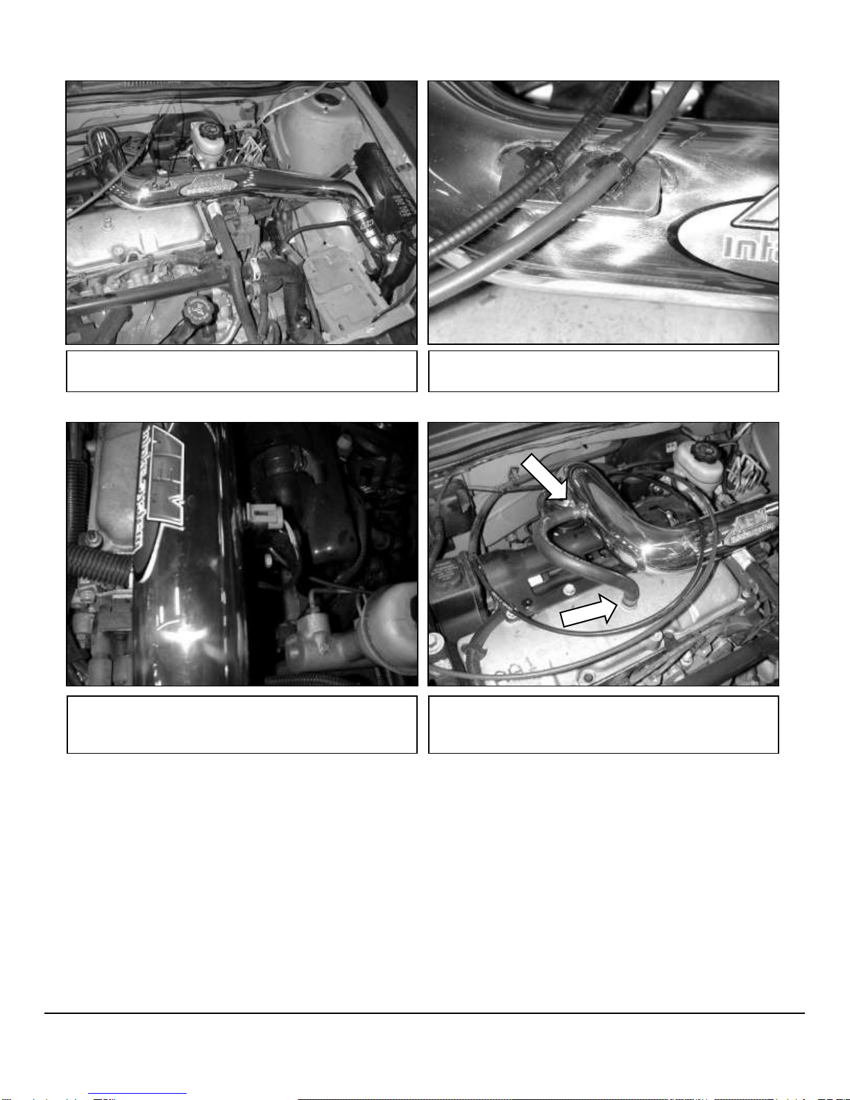
9
f. Install the supplied silicone hose as shown. Orient
the hose clamp screws away from the battery tray as
shown.
g. Attach the rubber mount to the tab near the washer
bottle filler neck using the supplied washer and lock
nut.
h. Install the hump hose to the throttle body as shown.
Cruise control only.
i. Install the supplied grommet in the hole on the upper
pipe. Insert the zip tie into the hole on the upper pipe
bracket (use two zip ties if the car has cruise control).
10
j. Place the upper intake pipe in the engine bay as
shown.
k. Secure the throttle/cc cable(s) to the upper pipe with
the zip tie(s) installed earlier. Cut off excess material.
l. Insert the IAT sensor through the grommet in the
upper pipe. Do not push the grommet into the pipe.
m. Install the supplied breather hose between the valve
cover and intake pipe. Secure it with the supplied hose
clamps.

11
4. Reassemble Vehicle
a. Fender liner: Install the fender liner and any hardware that was removed in steps 2k.
NOTE: Failure to install the fender liner will result in diminished performance and increase the
potential for engine damage due to water ingestion in rainy conditions.
b. Wheel: Install the driver’s side wheel using the factory torque specification (see owner’s manual).
c. Washer Bottle: Refill the washer bottle with the washer fluid that was drained in step 2m.
d. Position the inlet pipes for the best fitment. Be sure that the pipes or any other components do not contact
any part of the vehicle. Tighten the rubber mount, all bolts, and hose clamps.
e. Check for proper hood clearance. Re-adjust pipes if necessary and re-tighten them.
f. Inspect the engine bay for any loose tools and check that all fasteners that were moved or removed are
properly tightened.
g. Reconnect battery terminals and start engine. Let the vehicle idle for 3 minutes. Perform a final inspection
before driving the vehicle.
n. Check the fitment of the pipes and tighten all hose
clamps. Secure the fuse block to the rubber mount
with the supplied lock nut and washer.
o. Reinstall the battery. Confirm that the positive lead
from the fuse box is on top of the intake pipe and is not
pinched between the battery and the intake pipe.
p. Install the air filter onto the end of the intake pipe.
AEM®intake system installed
12
For technical inquiries
e-mail us at
sales@aemintakes.com
or
call us at
800.992.3000
5. CARB Sticker Placement
a. The C.A.R.B. exemption sticker, (attached), must be visible under the hood so that an emissions
inspector can see it when the vehicle is required to be tested for emissions. California requires testing
every two years, other states may vary.
6. Service and Maintenance
a. AEM Induction Systems requires cleaning the intake system’s air filter element every 100,000 miles. When
used in dusty or off-road environments, our filters will require cleaning more often. We recommend that you
visually inspect your filter once every 25,000 miles to determine if the screen is still visible. When the screen
is no longer visible some place on the filter element, it is time to clean it. To clean, purchase our Synthetic air
filter cleaner, part number 99-0624 and follow the easy instructions.
b. Use window cleaner to clean your powder coated AEM®intake tube.
NOTE: DO NOT USE aluminum polish on powder coated AEM®intake tubes.
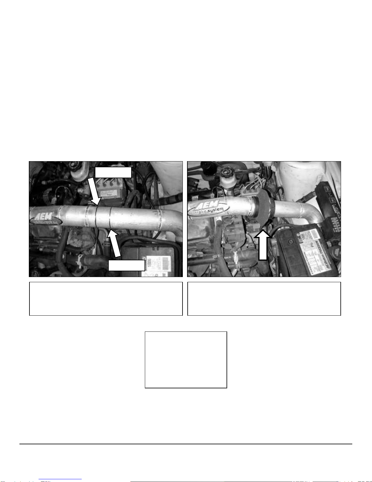
7. Notes on installing AEM bypass valve (part # 20-402S –sold separately)
Cut here.
And here
Suggested location to cut intake pipe to install AEM®
bypass valve. Be sure to follow the installation
instructions included with the AEM®Bypass Valve to
ensure proper installation.
AEM®bypass valve installed.

13
AEM Air Intake System Warranty Policy
AEM®warrants that its intake systems will last for the life of your vehicle. AEM will not honor this warranty due to
mechanical damage (i.e. improper installation or fitment), damage from misuse, accidents or flying debris. AEM will
not warrant its powder coating if the finish has been cleaned with a hydrocarbon-based solvent. The powder
coating should only be cleaned with a mild soap and water solution. Proof of purchase of both the vehicle and AEM
intake system is required for redemption of a warranty claim.
This warranty is limited to the repair or replacement of the AEM part. In no event shall this warranty exceed the
original purchase price of the AEM part nor shall AEM be responsible for special, incidental or consequential
damages or cost incurred due to the failure of this product. Warranty claims to AEM must be transportation prepaid
and accompanied with dated proof of purchase. This warranty applies only to the original purchaser of product and
is nontransferable. Improper use or installation, use for racing, accident, abuse, unauthorized repairs or alterations
voids this warranty. AEM disclaims any liability for consequential damages due to breach of any written or implied
warranty on all products manufactured by AEM. Warranty returns will only be accepted by AEM when accompanied
by a valid Return Merchandise Authorization (RMA) number. Credit for defective products will be issued pending
inspection. Product must be received by AEM within 30 days of the date RMA is issued.
If you have a warranty issue, please call (800) 992-3000 and our customer service department will assist you. A
proof of purchase is required for all AEM warranty claims.
10-7022C
04/19/12
Table of contents
Other AEM Water Filtration System manuals


