AEMC instruments PEL 102 Use and care manual

2021© Chauvin Arnoux® Inc d.b.a. AEMC® Instruments. All rights reserved.
AEMC® Instruments retains the right to make changes herein at any time, without notice.
BATTERY REPLACEMENT PROCEDURE
POWER & ENERGY LOGGERS
MODELS PEL 102 & PEL 103
(Battery for Cat. #’s 2137.51, 2137.52, 2137.61, 2137.62)
The Power & Energy Loggers PEL 102/103 include an 8.4V NiHM
battery pack (Cat. #2137.81) for backup power. This battery can
be replaced by the user. The battery should only need to be
replaced approximately every three or four years. This battery is
available for purchase directly on our storefront at:
www.aemc.com/store

Model PEL 102/103 Battery Replacement Procedure Cat. #2137.81
2
IMPORTANT WARNING!
The PEL battery replacement must be performed
carefully and in strict accordance with the
procedure described in this manual. Any deviation
from the procedure could result in damage to the
instrument and may void your warranty.
If you are unsure about performing this procedure,
return the PEL to AEMC® for a factory battery
replacement.
Before You Begin
To replace the battery in the PEL, you will need the following:
A clean work surface free of debris, water, and other
possible contaminants. This surface should be well-lighted
and provide sufficient room to perform the steps below.
8.4V NiHM battery pack.
Torx T10 screwdriver (Torx-type screwdrivers are also
known as “star” screwdrivers).
Tape (masking, electrical, etc.)
(Optional) A small, non-conducting implement, such as a
drink stirring stick or toothpick.
Before starting this procedure, we recommend that you view the
instructional video AEMC® - PEL 102 103 Battery Replacement on
our AEMC YouTube channel.
Please note that the battery pack shown in the following
illustrations may differ in color from your battery.
However, the steps in the procedure are identical.
Model PEL 102/103 Battery Replacement Procedure Cat. #2137.81
3
Battery Replacement Procedure
To replace the battery in the PEL 102/103, disconnect the
instrument from all electrical sources and sensor probes. Then
follow these steps:
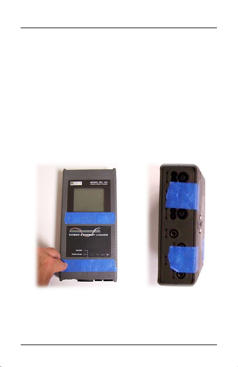
1. Apply tape to the control buttons on the PEL front panel (see
Figure 1). This tape will ensure that the buttons remain in
place when you remove the PEL’s front cover from the back
cover.
2. Tape the PEL’s endplates to the back cover (see Figure 2).
This helps to ensure that the endplates remain attached to the
back cover when you remove the front cover.
Figure 1 Figure 2
Model PEL 102/103 Battery Replacement Procedure Cat. #2137.81
4
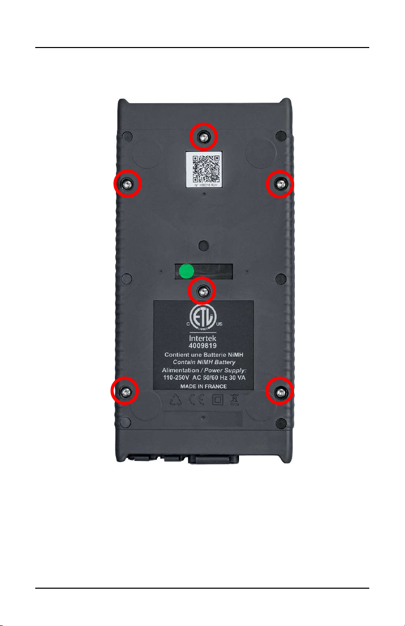
3. Turn over the PEL, and locate the six fastening screws on the
back of the instrument.
Figure 3
4. Use a Torx T10 screwdriver to remove these fastening
screws.
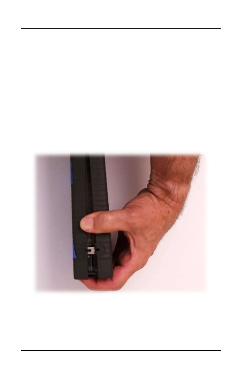
5. Carefully separate the front cover of the PEL from the back
cover. Typically, the two covers fit together tightly, so it may
be difficult to separate them at first.
Model PEL 102/103 Battery Replacement Procedure Cat. #2137.81
5
One way to do this is to turn the instrument on its side, as
shown in Figure 4, and then carefully separate each corner in
turn starting with the bottom right corner. With your fingers on
the bottom endplate, pull the covers apart while ensuring that
the endplate remains attached to the back cover.
CAUTION: Do not allow either the top or bottom endplate
to separate from the back cover. This may cause damage
to the input and connection terminals that would require
the PEL to be sent to AEMC for repair.
Figure 4

Model PEL 102/103 Battery Replacement Procedure Cat. #2137.81
6
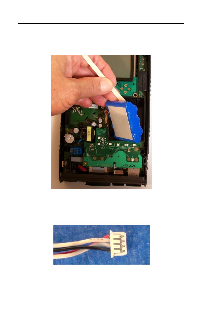
6. With the front cover removed, locate the battery pack.
Figure 5
Model PEL 102/103 Battery Replacement Procedure Cat. #2137.81
7
7. Gently remove and unplug the battery from the PEL. A small
non-conductive implement such as a drink stirring stick
(shown below) can be useful for this step.
Figure 6
8. Inspect the plug of the replacement battery back, and note the
position of the connector pins.
Figure 7

Model PEL 102/103 Battery Replacement Procedure Cat. #2137.81
8
9. Position the plug with the connector pins facing away from the
battery pack compartment. In the illustration below, the pins
are facing towards the left. Then, very carefully insert the plug
by gently pushing it into the socket within the PEL. There is
very little room for this procedure, so a non-conducting
implement, such as a stirring stick or toothpick, may be helpful
in ensuring the plug is securely inserted.
WARNING: The PEL instrument will likely turn on when
you plug in the connector. Please ensure that you do
not touch exposed circuitry as it is now energized
and can pose a shock or damage hazard.
Figure 8

Model PEL 102/103 Battery Replacement Procedure Cat. #2137.81
9
10. Place the replacement battery into the compartment provided
for it within the PEL. When doing this, ensure that the
battery’s connector wires are positioned as shown in Figure 9
below. Be sure that the wires do not cross over the top of
the post as shown in Figure 10 below. If the wires are
placed over the post, the wires will likely be damaged
when you replace the PEL top cover.
Figure 9
Figure 10

Model PEL 102/103 Battery Replacement Procedure Cat. #2137.81
10
11. Replace the front cover while carefully ensuring that it is
securely in place.
12. Turn the PEL over, and replace the six fastening screws
removed in step 3 of this procedure.
13. Remove the tape applied to the front cover and endplates
at the beginning of this procedure. The PEL is now ready
for operation.

NOTES:

11/21
99-MAN 100410 v4
Chauvin Arnoux®. Inc. d.b.a. AEMC® Instruments
15 Faraday Drive • Dover, NH 03820 USA
Phone: (603) 749-6434 • (800) 945-2362 • Fax: (603) 742-2346
www.aemc.com
This manual suits for next models
1
Table of contents


