Eagle EV-30 User manual

rev_0.6 2 / 135
Table of Contents
Introduction
How to Use This Owner's Manual
Notes Used in This Manual
Safety
Laser Safety
Electrical Safety
Installation
Get to Know the Components of the Laser System
Get Prepared for the Installation
Unpacking the Laser System
Set up the Machine
(For 3kW Only) Set up the Control Console
(For 6kW Only) Set up the Control Console
(For 6kW Only) Install the Fiber Laser
Connecting the Chiller
Connecting the Exhaust(s)
Connecting the Voltage Regulator
Connecting the Transformer
Connecting the Assist Gas
Getting Started
Turn on the Laser System
Turn off the Laser System
Handheld Remote
CypCut Basics
Parts in CypCut
Operation
Hints for Programming Parts
Import Parts
Construct Parts
Part Library
Nest Parts
Technology in CypCut
Hints for Setting Technology
Cutting Parameters

rev_0.6 3 / 135
Lead-Ins and Lead-Outs
Kerf Compensation
Microjoints
Technologies for Getting Good Corners
Automatically Applied Technologies When Nesting
Auxiliary Technologies
Check Technology
Appendix A: (For 6kW Only) Install the Fiber Laser
If any details in this manual is unclear or if you need additional assistance setting up your machine, please feel
free to call us at +1 (626) 671-4014 or email at [email protected].

rev_0.6 4 / 135
Introduction
How to Use This Owner's Manual
Thank you for purchasing a GU Eagle EV-30 industrial fiber laser cutting system. This laser system has been
designed to be easy to operate, but you will utilize it to its fullest potential by taking some time to read this
owner's manual prior to use. You will be ready to use the laser system as soon as you read the first few
sections. Then you can refer to topics in the remaining sections, as you work.
Notes Used in This Manual
Look for these kinds of notes to help you find valuable information throughout the text:
NOTE
Helpful notes to keep in mind while running the laser!
IMPORTANT
Important instructions you should always follow.
WARNING
Warnings and cautions to keep in mind while running the laser.

rev_0.6 5 / 135
Safety
Laser Safety
Lasers use intense beams of light to create heat and fire as a normal part of their operation, and depending
on the laser, the light might not be visible to you. If the proper safety measures are ignored, you could burn
or blind yourself or someone else, or start a fire that could damage or destroy the building in which the laser
system is housed.
IMPORTANT
ALWAYS wear protecting glasses while doing laser processing.
WARNING
DO NOT aim and fire laser on anything but the workpieces you want to process.
WARNING
DO NOT leave a running laser unattended.
The visible output beam of the Laser Diode Pointer (Red Dot Pointer) is accessible to the operator. While this
device employs the same technology as the familiar laser pen-pointers, like them it is potentially hazardous if
its beam is directed into the eye.
WARNING
DO NOT view directly into the beam of the Laser Diode Pointer (Red Dot Pointer).
Electrical Safety
The AC input power to the machine is potentially lethal and is fully contained within the cabinet.
WARNING
DO NOT open any of the machine's access panels while the unit is plugged in. Opening a panel may
expose the operator to the unit's AC input power.
WARNING
DO NOT make or break any electrical connections to the machine while the unit is turned on.

rev_0.6 6 / 135
Installation
Follow the steps below to set up your EV-30 laser system, and to be ready to get started.
1. Get to know the components of the laser system.
2. Get prepared for the installation.
3. Unpack the laser system.
4. Set up the machine.
5. (For 3kW only) Set up the control console.
6. (For 6kW only) Set up the control console.
7. (For 6kW only) Install the fiber laser.
8. Connect the chiller.
9. Connect the exhaust(s).
10. Connect the voltage regulator.
11. Connect the transformer.
12. Connect the assist gas.

rev_0.6 7 / 135
Get to Know the Components of the Laser System
The EV-30 industrial fiber laser cutting system is composed of a machine, a control console, a fiber laser (pre-
installed inside the machine for 3kW lasers), a chiller, two exhausts (only one stronger exhaust for 6kW lasers),
a voltage regulator, a transformer, and a set of appropriate assist gas (prepared by customers).
The picture below shows the schema of the laser system in the recommended footprint configuration for 3kW
lasers. For a 6kW laser system, the fiber laser will stand alone in front of the chiller.

rev_0.6 8 / 135
Get Prepared for the Installation
We would recommend that you get your facilities prepared before your laser system shipping. That will save a
lot of time during the installation, especially for the customers who are far from our service agencies.
1. The Recommended Footprint Configuration of the EV-30 Laser System

rev_0.6 9 / 135
The weight of the machine is around 4500lbs, 2000kg. Precise leveling of the ground is not necessary,
but it should be reasonably level and sturdy enough to support the machine well.
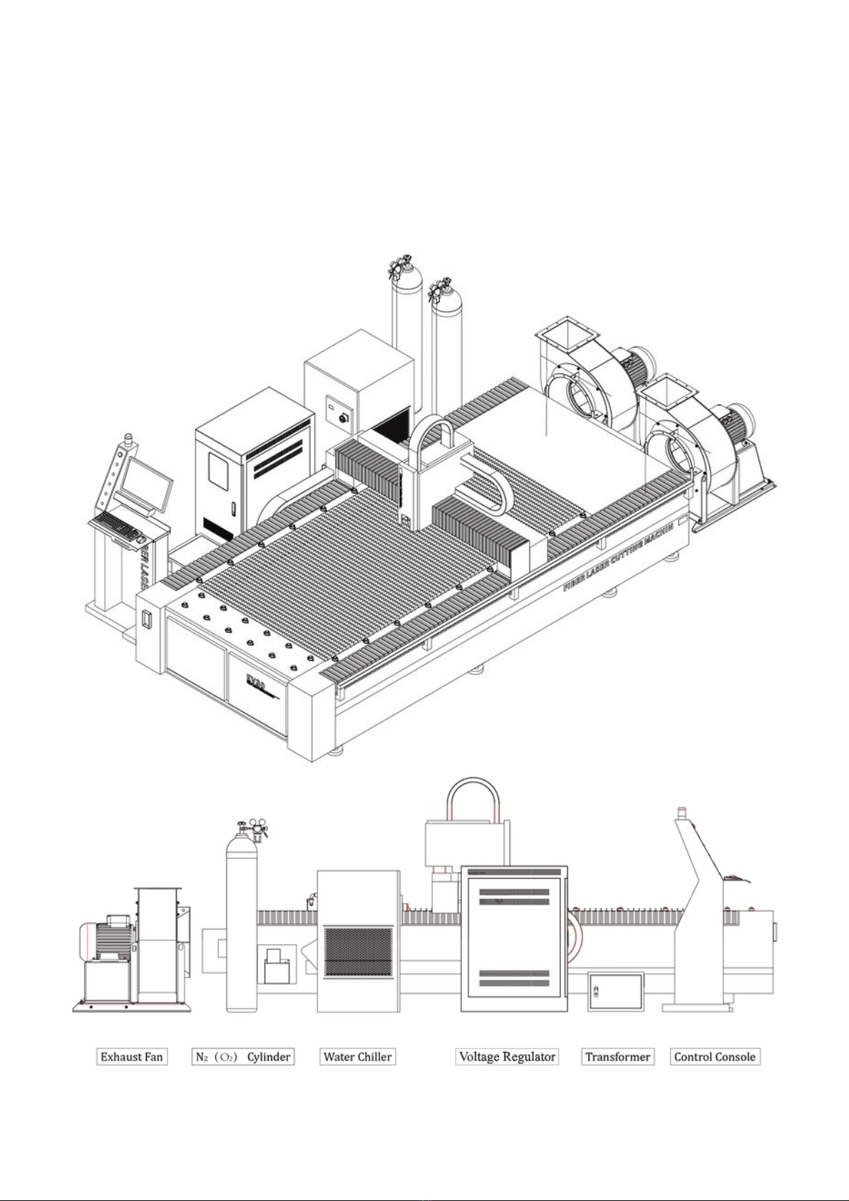
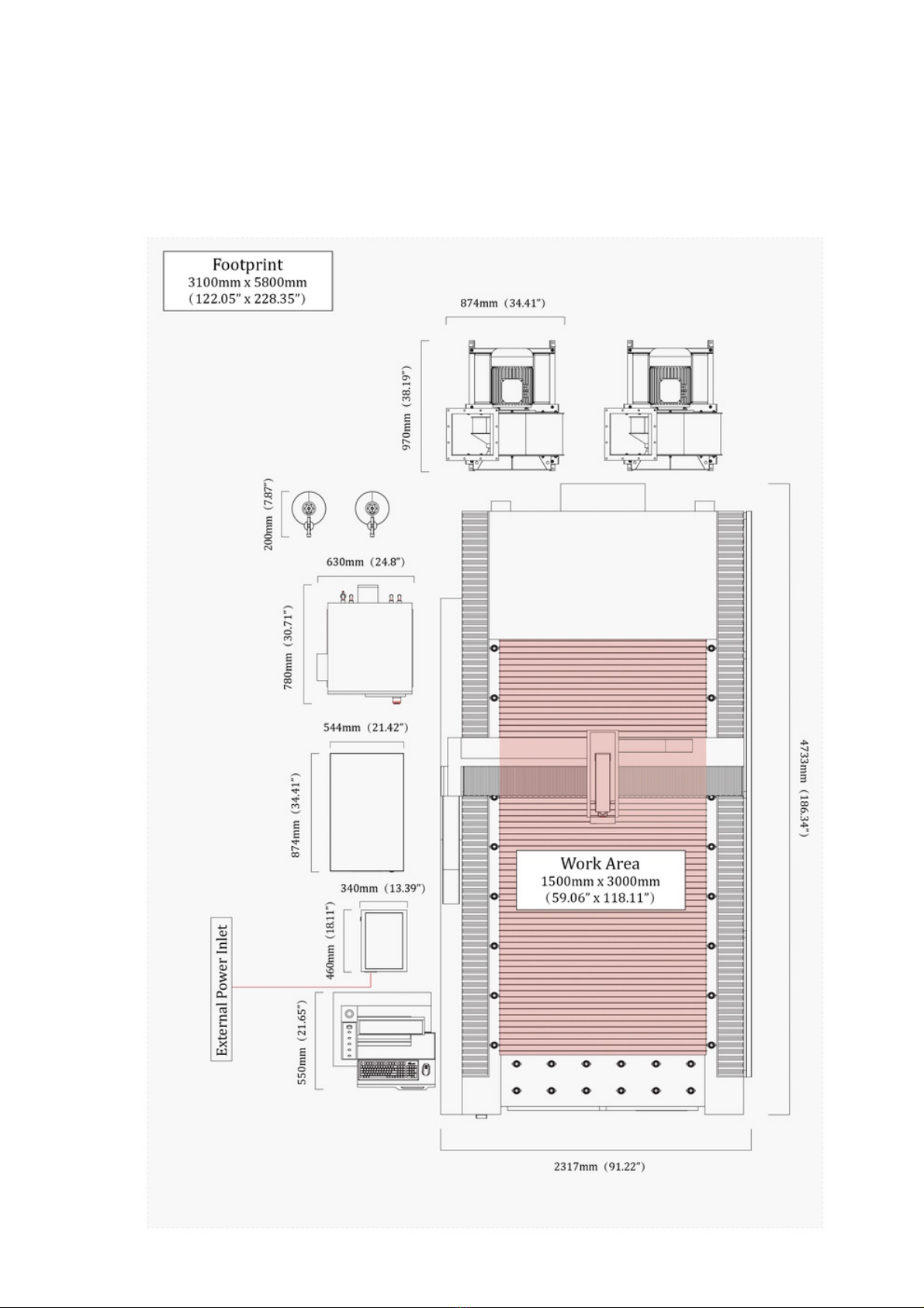
The laser system comes with a 16ft, 5m power cord, prepare the electrical power interface in a
reachable position according to the transformer in the footprint.
The assist gas system should be set according to the gas cylinder in the footprint.
The duct work should be set close to the exhaust(s) if there is such a system in your facility.
There should be enough space to load sheets onto the cutting bed from the front and the right side of
the machine.
2. Electrical Power Requirements
The EV-30 laser system requires 3-phase 480-volt electrical power. The overall power consumption will
differ according to the laser configuration of your system.
Laser Configuration Overall Power Consumption
3 kW 40 kW
6 kW 80 kW
NOTE
It is recommended that a dedicated circuit be used if available, but it is not required.
3. Cooling Requirements
Laser technology is such that the laser units generate a lot of excess heat and the units must be cooled
for proper operation. The EV-30 laser system comes with a chiller to do this job, which needs to be
filled up with appropriate water.
Water Type Water Consumption
Purified / Distilled 15-40 L (4-10.5 gal)
IMPORTANT
Other types of water may corrode the pipeline inside the fiber laser, and weaken the cooling
effects.
IMPORTANT
Add antifreeze to cooling water to protect the fiber laser from freezing if the ambient
temperature could be below 5°C (41°F). Otherwise, it may cause SEVERE DAMAGE to the core
components of the laser.

rev_0.6 10 / 135
4. Assist Gas for Cutting
During the laser cutting process, a laser is used as a heat source to melt or vaporize materials. To cut
the materials with a high-quality edge, an assist gas blows through a cutting nozzle on the laser head.
The right assist gas can improve the edge quality and can increase the cutting speeds substantially for
certain materials.
Gas Purity Pressure
Nitrogen (N2)≥ 99.99% 10-20 bar
Oxygen (O2)≥ 99.99% 2-10 bar
Compressed Air Water free, oil free 10-20 bar
IMPORTANT
If compressed air is used as the assist gas, make sure it is WATER FREE AND OIL FREE.
Otherwise, the protective lens in the laser head will get dirty and wet, and will be broken by the
laser while cutting.
5. Operating Environment
The EV-30 laser system should be operated in an environment with appropriate ambient temperature
and humidity.
Ambient Temperature Humidity
10-40 °C (50-104 °F) 10-80%
IMPORTANT
The laser system must not operate at temperatures below the respective ambient dew point.
IMPORTANT
Use heating equipment to keep the ambient temperature of the working area where the laser is
located above 0°C (32°F) if there is no antifreeze in cooling water. Generally, it is more
appropriate to set the temperature above 5°C (41°F).

rev_0.6 11 / 135
Unpacking the Laser System
Follow the steps below to unpack and place all the components of the EV-30 laser system, refer to The
Recommended Footprint Configuration of the EV-30 Laser System for more details.
1. Remove all the protective films and the packing materials on the machine, set it in place, and set all the
accessory packs to the right side for now.
2. Remove the packing materials on the control console, and set it to the front of the left side of the
machine.
The control console for 3kW lasers.

rev_0.6 12 / 135
The control console for 6kW lasers.
3. Remove the packing materials on the voltage regulator, and set it to the middle of the left side of the
machine.

rev_0.6 13 / 135
4. (For 6kW only) Remove the packing materials on the fiber laser, and set it to the back side of the
voltage regulator.
5. Remove the packing materials on the transformer, and set it to the front side of the voltage regulator.
6. Remove the packing materials on the chiller, and set it to the rear of the left side of the machine.

rev_0.6 14 / 135
7. Remove the packing materials on the exhausts (only one exhaust for 6kw lasers), and set them to the
back side of the machine.

rev_0.6 15 / 135
Set up the Machine
1. Secure the machine in place.
After positioning, secure the machine in place by screwing the leveling feet down until they are in firm
contact with the ground.
NOTE
Precise leveling of the machine is not necessary, but it should be reasonably level and well-
supported with roughly equal pressure on all feet.

rev_0.6 16 / 135
2. (For 6kW only) Set the Y axis drag chain and its related parts in place.
The Y axis drag chain and its related parts are removed and put on the cutting bed during shipping.
First, assemble the base of the Y axis drag chain on the left side of the machine, put the drag chain on
it, and fix the end of the drag chain. Second, assemble the X-Y intersection part on the left end of the
gantry, and fix the other end of the drag chain on it. Finally, tighten the cables, and pack up the section
of the cables out of the drag chain.
IMPORTANT
The cables are pre-set through inside the drag chain and the parts, which should be set up
carefully and gently to avoid damaging the cables.

rev_0.6 17 / 135
3. Remove the gantry locking blocks.
The gantry of the machine is locked up with three locking blocks to avoid damage during shipment.
Make sure to remove them before powering on the machine.
IMPORTANT
The machine will DAMAGE itself if the laser head starts moving while the locking blocks are still
in place.
NOTE
Make sure to SAVE to all the locking blocks in case you need to move the machine in the future.

rev_0.6 18 / 135
4. Assemble the guard rails.
The guard rails are meant to keep people from getting too close the potentially dangerous cutting area
while the machine is in operation.
5. Set the pick-up drawers.
The machine comes with two pick-up drawers, which to be placed under the front half and the rear half
of the cutting bed.
After processing, parts small enough to fit through the strip cutting bed will drop down to deep
collecting bays, avoiding damage by the laser during subsequent cutting operations. They can be
retrieved simply by pulling out the drawers after cutting is complete.

rev_0.6 19 / 135
(For 3kW Only) Set up the Control Console
1. Assemble the monitor.
Take out the monitor from the accessories pack, assemble it onto the control console frame, and
connect the cables.
2. Put the keyboard, mouse and the handheld remote on the console.
3. Assemble the alarm indicator.
Remove the back cover of the panel box, assemble the alarm indicator, connect the wires, and then put
the cover back.
4. Connect the computer.
Open the left access panel on the front of the machine, take out the computer from the package,
connect the cables, and then close the panel.

rev_0.6 20 / 135
(For 6kW Only) Set up the Control Console
1. Assemble the monitor.
Take out the monitor from the console cabinet, assemble it in place, and connect the cables.
2. Put the keyboard, mouse and the handheld remote on the console.
3. Assemble the alarm indicator.
Assemble the alarm indicator on the top of the console cabinet, and connect the wires.
4. Connect the cables.
Connect the cables from the machine to the console.
Table of contents
Other Eagle Industrial Equipment manuals