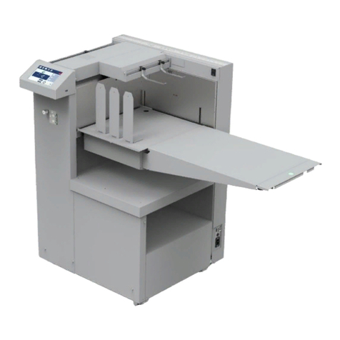
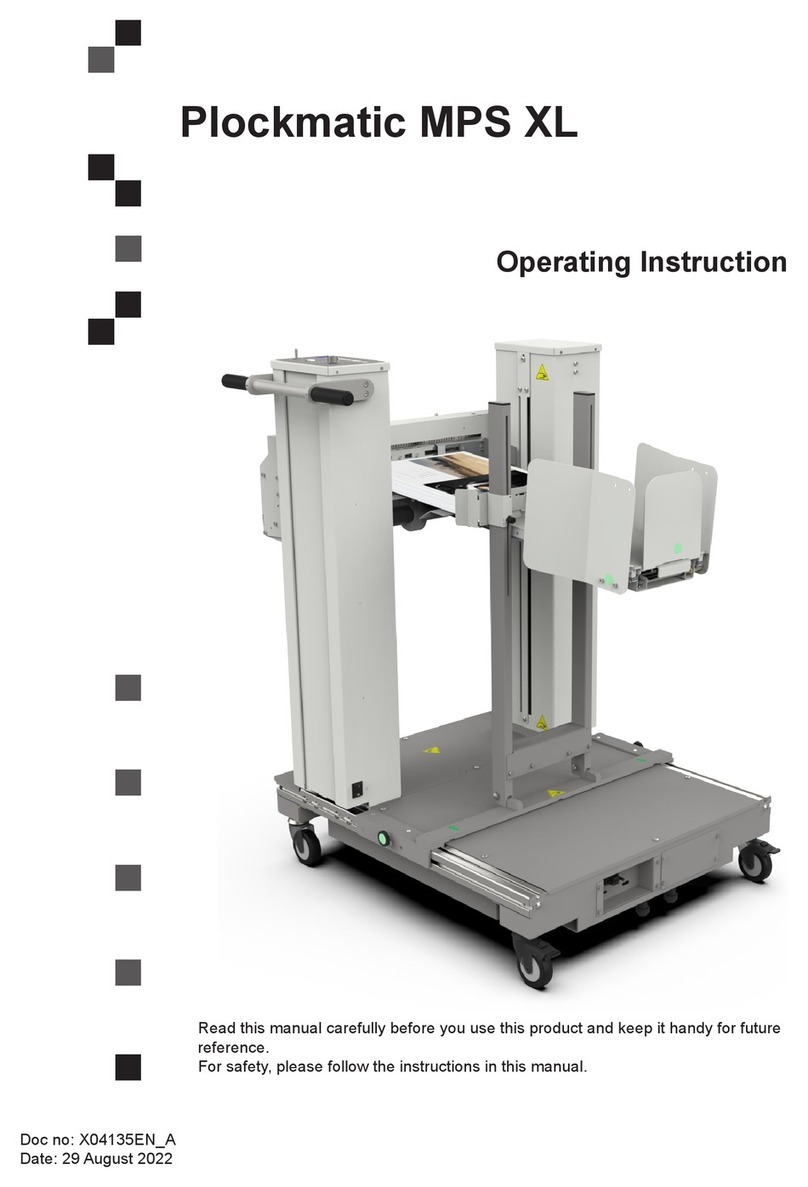
Plockmatic FeederPro 1000 User manual

Feeder Pro
Model 1000
Service Manual
March 2005
Part No. 18360

FEEDER PRO MODEL 1000 PAGE 2 MARCH-05
T08093
TABLE OF CONTENTS
1.1 PreventiveMaintenanceList.................................................................................... 5
2.1 GeneralCautions ..................................................................................................... 6
2.2 Special Tools............................................................................................................ 7
COVERS............................................................................................................................. 8
2.3 FrontCover ............................................................................................................. 8
2.4 Rear Door ............................................................................................................... 9
2.5 Display.................................................................................................................. 10
SENSORS.........................................................................................................................11
2.6 DoubleSheetDetectionSensorsQ17-Q24 ........................................................... 11
2.7 EmptyBinSensorsQ1-Q8 .................................................................................... 12
2.8 Bin Lift Motors Home Position Sensors Q9-Q16.................................................... 13
2.9 Conveyor BeltMotorSensorQ25 .......................................................................... 14
2.10 Stacker Motor Home Position Sensor Q26 ............................................................ 15
2.11 StackerFullSensorsQ27-Q28 .............................................................................. 16
2.12 HeightErrorSensorQ29 ....................................................................................... 17
SOLENOIDS...................................................................................................................... 18
2.13 Valve Bin Solenoids SOL1-SOL8 .......................................................................... 18
2.14 ClutchSOL9-SOL16 ............................................................................................. 19
2.15 ShuntPlateSolenoidSOL17 ................................................................................. 20
MOTORS ........................................................................................................................... 21
2.16 BinLiftMotorsM1-M8 ........................................................................................... 21
2.17 ConveyorBeltMotorM9 ........................................................................................ 22
2.18 StackerMotorM10................................................................................................ 23
2.19 VacuumAir Chamber ............................................................................................ 24
2.20 Fans FAN 1-2........................................................................................................ 25
2.21 Fan Motor Brushes ................................................................................................ 26
MECHANICS..................................................................................................................... 27
2.22 IdlerRoller ............................................................................................................. 27
2.23 DriveShaft ............................................................................................................ 28
FEEDER PRO MODEL 1000 PAGE 3 MARCH-05
T08093
2.24 Air Separation Chamberand exchanging Stop Fingers ......................................... 29
2.25 SuctionBeltassy................................................................................................... 31
2.26 SuctionBelt........................................................................................................... 33
2.27 TimingBelt ............................................................................................................ 34
ELECTRIC......................................................................................................................... 35
3.1 Circuit Boards ....................................................................................................... 35
3.2 Power Board......................................................................................................... 36
3.3 MD6DC Board ...................................................................................................... 37
3.4 CPU Board ........................................................................................................... 39
3.5 Software Download ............................................................................................... 40
3.6 BlownFuse Conditions.......................................................................................... 41
3.7 Schematic, Fans ................................................................................................... 42
SERVICEMENU ............................................................................................................... 43
4.1 ServiceMenu ........................................................................................................ 43
4.2 Self Diagnostics andTest Calibration .................................................................... 44
4.3 CheckMotors........................................................................................................ 45
4.4 Check Solenoids................................................................................................... 46
4.5 CheckSensors...................................................................................................... 47
4.6 Voltmeter............................................................................................................... 48
4.7 TotalCounter ......................................................................................................... 49
4.8 Fault Log ............................................................................................................... 50
4.9 Software Versions ................................................................................................. 51
4.10 NVM...................................................................................................................... 52
4.11 Reset NVM............................................................................................................ 53
FAULT CODES.................................................................................................................. 54
5.1 Diagnostic Fault Codes......................................................................................... 54
5.2 MalfunctionCodes................................................................................................. 61
5.3 NVM values ........................................................................................................... 62

FEEDER PRO MODEL 1000 PAGE 4 MARCH-05
T08093
PRINCIPLEOFOPERATION ............................................................................................. 63
6.1 Principleof Operations .......................................................................................... 63
B-TOWERSECTION ......................................................................................................... 64
7.1 B-TowerTransportSensors Q27-Q28 .................................................................... 65
7.2 BridgeTransport Belt............................................................................................. 66
7.3 OutfeedWheel ...................................................................................................... 70

FEEDER PRO MODEL 1000 PAGE 5 MARCH-05
T08093
1.1 Preventive Maintenance List
Wholemachine,
Paper path, Bins,
etc.
250 000 500 000
Instruction
Check point
Use vacuum cleaner, towels and brushes to
clean the machine from paper dust. Clean Clean
Suction Belts Use a rubber reactivator fluid to clean the Suction
Belts. See REP 2.26. Check/
clean Check/
clean
Separator Pads Check for wear. If worn, replace.
See REP 2.24. Check/
replace Check/
replace
Conveyor Belt Check the Conveyor Belt for wear. Use a soap
solution when cleaning. Check/
clean Check/
clean
Timing Belt Use a rubber reactivator alcohol fluid to clean the
belt. Check for wear, if worn replace. REP 2.27 Check/
clean Check/
clean
Rubber Wheel Check for wear. If worn, replace.
See REP 2.22. Check Check/
replace
Chains Lubricate Chains with oil. Grease Grease
Bushings Lubricate Bushings with oil. Grease Grease
Fan Motor
Brushes Replace Fan Motor Brushes every 1,5 million
sets. (Replace) (Replace)
Outfeed Wheels Check for wear. If worn, replace. Check Check/
replace
DSD Sensors Use compressed air to clean sensors. Check
DSD values acc. to REP. 2.6 Clean/
check Clean/
check
Sensors Use compressed air to clean sensors. Clean Clean

FEEDER PRO MODEL 1000 PAGE 6 MARCH-05
T08093
2.1 General Cautions
Using the ESD Ground Strap
Purpose
The purpose of the ESD (Electrostatic Discharge) ground strap is to preserve the inherent
reliability and quality of electronic components handled by the Service Representative. The strap
should be used whenever handling the circuit boards or any other ESD sensitive components.
Procedure
NOTE: All procedures requiring use of the ESD ground strap will contain a caution referring
to this procedure.
1 Switch off the main power switch.
2. Make sure the power cord connects the machine to the wall outlet. The power cord and wall outlet
must have ground.
3. Connect the claw end of the grounding cord to a chassis ground, such as earth wires screwed to
chassis ground, unpainted frame or an unpainted bracket secured to the frame.
4. Connect the snap end of the blue cord to the snap on the adjustable wriststrap.
5. Place the adjustable wriststrap securely on the wrist.
Wait for one minute to let the electrostatic be discharged from your body.
6. ESD sensitive components can now be handled without causing any ESD related damage.
7. New replacement PCBs and ESD sensitive components, as well as old defective PCBs should be
handled during unpacking and repacking using the ESD ground strap. During the transfer from or to
the packaging material, the PCB should be placed in the ESD bag the replacement PCB came in.
CAUTION
ESD Hazard! ESD (Electrostatic Discharge) can cause software crashes, data and/ or commu-
nications problems. Failure to use proper ESD procedures will cause damage to electronic
components (example: PCBs). ESD problems can be minimized by maintaining all machine
ground connections, ensuring the proper handling of circuit boards/ sensors.
NOTE: Use ESD protection when working near PCBs. Failure to use ESD protection is likely
to result in a PCB failure.

FEEDER PRO MODEL 1000 PAGE 7 MARCH-05
T08093
2.2 Special Tools
In order to facilitate the service of the Model 1000 there are a few special tools needed.
Where part number is written it can be purchased from your supplier.
Hand Crank Generator
- Part no. 551249
ESD Ground Strap
- Part no. 901044
Laptop Computer
With COM1 serial interface port. If the computer lacks COM1 serial interface port, an
adaptor cable from USB to serial interface is needed along with necessary drivers to
establish a COM1 port. Purchase such adaptor cable from your local PC vendor.
Download Cable
- Part no. 770010
Torx 20 Screwdriver

FEEDER PRO MODEL 1000 PAGE 8 MARCH-05
T08093
2.3 Front Cover
REMOVAL
1. Loosen screw (1).
2. Lift off cover by pulling out lower end and lift up.
REPLACEMENT
1. Installation is an exact reversed procedure of removal.
1

FEEDER PRO MODEL 1000 PAGE 9 MARCH-05
T08093
2.4 Rear Door
OPEN
1. Turn screws (1) 1/4 of a revolution.
1
WARNING! Inside Rear Door
contains 230/115 VAC even if
Main Power Switch is off. Discon-
nect Power Cord before opening
Rear Door.

FEEDER PRO MODEL 1000 PAGE 10 MARCH-05
T08093
2.5 Display
REMOVAL
1. Remove Front Cover according to REP 2.3.
2. Loosen screws (2) (Do not remove).
3. Disconnect cable (1).
4. Lift out Display assy.
1
REPLACEMENT
1. Installation is an exact reversed procedure of removal.
2
3
Note. The harness for the Display can be removed from the clamps (3).

FEEDER PRO MODEL 1000 PAGE 11 MARCH-05
T08093
REMOVAL
1. Open Conveyor Belt Door and remove door by lifting upper hinge.
2. Remove paper guide plate by removing three screws (1) and loosen nearest paper guide plate.
3. Remove double sheet circuit printed board by removing screws (2).
2.6 Double Sheet Detection Sensors Q17-Q24
REPLACEMENT
1. Installation is an exact reversed procedure of removal.
2. GotoService Mode, Check Sensors.
3. Put a calibration strip between LED and phototransistor. The calibration strip is located left to the
uppermotordrive board.
4. Adjust trimpots to 4,64 V +- 0,05 V on CPU PCB.A is bin 1, B is bin 2 etc. (3).
Note. To facilitate procedure remove Display assy according to REP 2.5 and place it so
that it can be viewed from rear side of machine.
1
2
CAUTION: When removing the paper guide plate, stay clear from the printed board to
prevent damage.
3

FEEDER PRO MODEL 1000 PAGE 12 MARCH-05
T08093
REMOVAL
1. Go to service meny, RUN MOTORS, see chapter 4, and lift above bin for better access.
2. Remove sensor.
2.7 Empty Bin Sensors Q1-Q8
REPLACEMENT
1. Installationis anexactreversed procedureofremoval.
ADJUSTMENT
1. Sensorarmshould be 15 mm (3/5”) fromsensorbracket.
2. Push sensor arm in upper most position. Load one sheet in bin.
3. Goto Check Motors, see chapter 4.3.
4. Run liftmotor for specified bin. Motor should stop in upper position by sensor. If motor does not stop,
adjustsensor arm.
15 mm
(3/5”)

FEEDER PRO MODEL 1000 PAGE 13 MARCH-05
T08093
2.8 Bin Lift Motors Home Position Sensors Q9-Q16
REMOVAL
1. Open Back Door according to REP 2.4.
2. Go to service meny, RUN MOTORS, see chapter 4, and lift bin for better access.
3. Remove sensor (1).
1
REPLACEMENT
1. Installation is an exact reversed procedure of removal.

FEEDER PRO MODEL 1000 PAGE 14 MARCH-05
T08093
2.9 Conveyor Belt Motor Sensor Q25
REMOVAL
1. Open Back Door according to REP 2.4.
2. Remove conveyor belt motor according to 2.17.
3. Remove sensor (1).
REPLACEMENT
1. Installation is an exact reversed procedure of removal.
CAUTION: When removing the Conveyor Belt Motor, stay clear from the side frame
to prevent damage on sensor.
1

FEEDER PRO MODEL 1000 PAGE 15 MARCH-05
T08093
2.10Stacker Motor Home Position Sensor Q26
REMOVAL
1. Open Rear Door according to REP 2.4.
2. Remove Stacker Motor bracket according to REP 2.18.
3. Remove Sensor.
1
REPLACEMENT
1. Installation is an exact reversed procedure of removal. RED
BLACK
BLACK
WHITE
BLACK WHITE
RED
BLACK
Dot indicates LED side.
NOTE: There are two different models of the sensor.

FEEDER PRO MODEL 1000 PAGE 16 MARCH-05
T08093
2.11Stacker Full Sensors Q27-Q28
REMOVAL
1. Remove screws (1) and disconnect sensor.
Note: Upper sensor is Q28 and lower sensor is Q27.
REPLACEMENT
1. Installation is an exact reversed procedure of removal.
1
NOTE: In tower with integral stacker Q27 and Q28 are used as stacker full sensors. In towers with inbuilt
bridge Q27 and Q28 are used as detecting paper transport at bridge between towers.
Q28 when activated in tower with integral stacker, the machine will stop for stacker full.
Q27 is not in use in machines with integral stacker.

FEEDER PRO MODEL 1000 PAGE 17 MARCH-05
T08093
2.12Height Error Sensor Q29
REMOVAL
1. Open Rear Door according to REP 2.4
2. Go to service meny, RUN MOTORS, see chapter 4, and lift above bin for better access.
3. Removesensor.
REPLACEMENT
1. Installation is an exact reversed procedure of removal.
Thepurpose of the sensor istoprevent machine from breaking. When liftmotorsare activated and not
stoppedby empty bin sensor, before reaching mechanical stop, height error sensor willbeactivated. When
height error sensor is activated it will shut off power to the liftmotors.

FEEDER PRO MODEL 1000 PAGE 18 MARCH-05
T08093
REMOVAL
1. Open Rear Door according to REP 2.4..
2. Remove Vacuum Air Chamber according to REP 2.19.
2. Disconnect solenoid.
3. Remove screws (1).
4. Remove screws (2).
REPLACEMENT
1. Mount screws (1 and 2) but do not tighten.
2. Press plunger to inner most position (activated), move Solenoid to almost fully open position of the
valve. Valve flag should be 0-5° angle from fully open position. Tighten screws (2).
3. Adjust plunger to fully closed position of the valve, tighten screws (1).
Note: When valve is fully closed you will see the flag through hole (3).
1
2
2.13Valve Bin Solenoids SOL1-SOL8
3
FLAG
Orange
Violet
FLAG
CLOSED
FLAG
OPEN
0-5°

FEEDER PRO MODEL 1000 PAGE 19 MARCH-05
T08093
REMOVAL
1. Remove Front Cover according to REP 2.3.
2. Remove R-pin. Form R-pin if necessary.
3. Disconnect clutch.
4. Remove clutch.
REPLACEMENT
1. Installation is an exact reversed procedure of removal.
2.14Clutch SOL9-SOL16
Note: Use attached R-pins (located below shunt plate solenoid) and bend the straight leg to prevent
R-pin from falling off. Do not use old R-pin due to risk of breaking (1).
1
Other manuals for FeederPro 1000
1
Table of contents
Other Plockmatic Industrial Equipment manuals

Plockmatic
Plockmatic SF 4000 User manual

Plockmatic
Plockmatic Pro XL User manual

Plockmatic
Plockmatic BM3000 User manual

Plockmatic
Plockmatic MPS XL User manual

Plockmatic
Plockmatic Morgana PowerSquare 160 User manual

Plockmatic
Plockmatic HCI3500 User manual

Plockmatic
Plockmatic 510 User manual

Plockmatic
Plockmatic HCI3500 User manual

Plockmatic
Plockmatic Morgana VFL Feeder User manual