4
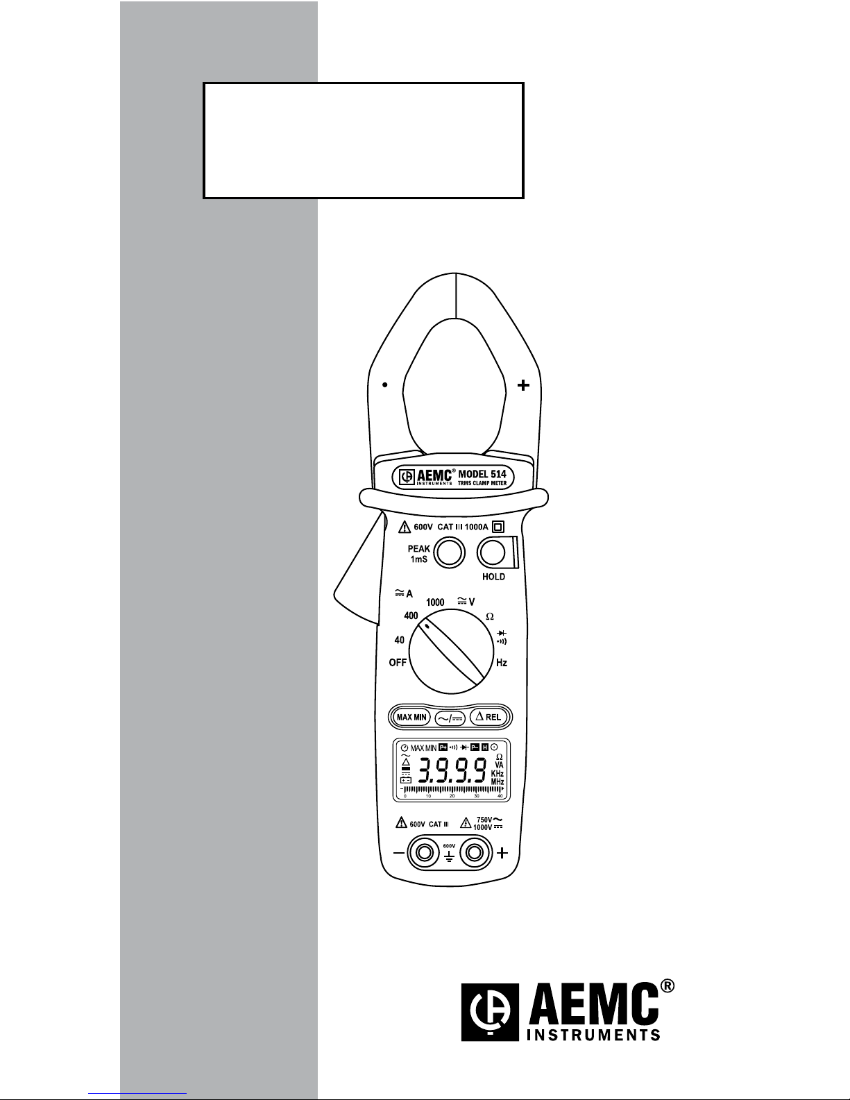
Clamp-on Meter Model 514
1.2 Definition of Measurement Categories
CAT II: For measurements performed on circuits directly
connected to the electrical distribution system.
Examples are measurements on household
appliances or portable tools.
CAT III: For measurements performed in the building
installation at the distribution level such as on
hardwiredequipmentinxedinstallationandcircuit
breakers.
CAT IV: Formeasurementsperformedattheprimaryelectri-
calsupply(<1000V)suchasonprimaryovercurrent
protectiondevices,ripplecontrolunits,ormeters.
1.3 Receiving Your Shipment
Upon receiving your shipment, make sure that the
contentsareconsistentwiththepackinglist.Notifyyour
distributorofanymissingitems.Iftheequipmentappears
tobedamaged,leaclaimimmediatelywiththecarrier
and notify your distributor at once, giving a detailed
descriptionof any damage. Savethe damaged packing
containertosubstantiateyourclaim.
1.4 Ordering Information
Clamp-on Meter Model 514..................... Cat. #2117.70
Includes meter, pair of test leads (red/black with probe tips), 9V
battery, soft carrying case and a user manual.
1.4.1 Accessories and Replacement Parts
Setof2,5ftcolor-codedleads.................. Cat. #2140.68
ReplacementPouch .................................. Cat. #2118.94
Order Accessories and Replacement Parts Online
Check out our Storefront at www.aemc.com/store