Aeonmed Aeon7400A User manual

Aeon7400A Service Manual
i
Contents
Contents.........................................................................................................................................................i
1 Introduction.............................................................................................................................................1
1.1 Symbols.......................................................................................................................................2
1.2 Warranty considerations..............................................................................................................3
2 Description..............................................................................................................................................4
2.1 General description......................................................................................................................4
2.2 Features of Aeon7400A...............................................................................................................4
2.3 Specification................................................................................................................................5
3 Checking .................................................................................................................................................6
3.1 Preoperative Checkout procedures..............................................................................................6
3.2 Testing the gas supply pipeline and the gas cylinder...................................................................8
3.3 Monitoring Flow Control ..........................................................................................................10
3.4 Installing and testing of vaporizer.............................................................................................14
3.5 Testing alarm.............................................................................................................................15
3.6 Testing the Breathing System....................................................................................................16
3.7 Testing Ventilator.......................................................................................................................17
4 Theory and Diagram..............................................................................................................................19
5 User Maintenance..................................................................................................................................21
5.1 Repair Policy.............................................................................................................................22
5.2 Maintaining Outline and Schedule............................................................................................23
5.3 Replacing fuses .........................................................................................................................24


Aeon7400A Service Manual
1
1 Introduction
This service manual provides procedures for testing and maintaining the Aeonmed model
anesthetic machine. It is not intended to be a complete maintenance document; therefore, it
contains no disassembly or reassembly instructions.
Refer any repairs or adjustments that exceed the scope of this manual to the Service Center of
Beijing Aeonmed Co., Ltd by calling
800-810-8333 or 86-10-88799987-333
This manual contains proprietary information. It is intended for use only by individuals qualified in
the installation and maintenance of the Aeonmed anesthetic machine. Receipt, purchase, or
possession of this document in no way confers or transfers any other rights for the use of this
information. Disclosure or reproduction of the enclosed, without the written permission of Beijing
Aeonmed Co., Ltd is prohibited.
This manual is intended for use only by technicians who have successfully completed Beijing
Aeonmed Co., Ltd training on this product.
Beijing Aeonmed Co., Ltd believes the information herein is accurate but accepts no responsibility
for errors, omissions, or misrepresentation.
Aeon7400A Service Manual
2
1.1 Symbols
Warnings and Cautions indicate all the possible dangers in case of violation of the
stipulations in this manual. Refer to and follow them.
WARNING: indicates potential hazards to operators or patients
CAUTION: indicates potential damage to equipment
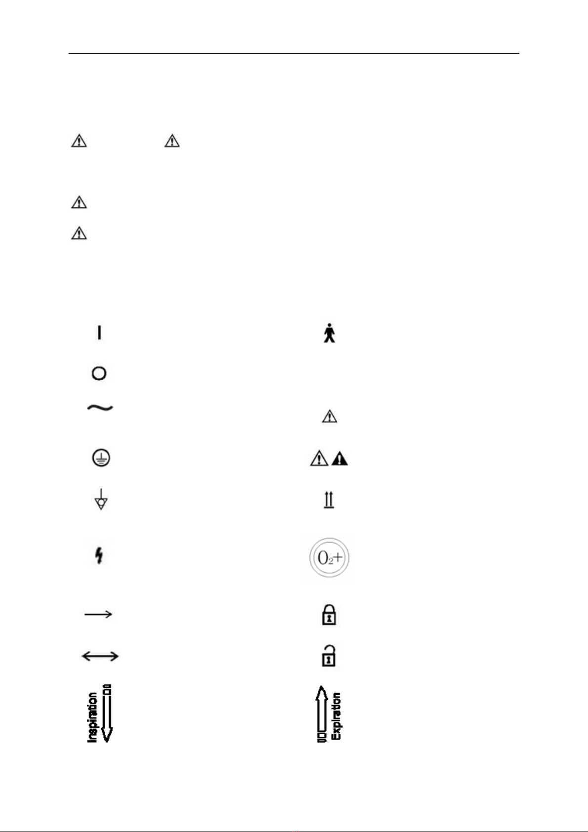
Instead of illustrations, other symbols may also be utilized. Not all of them may necessarily appear
in the equipment and manual. The symbols include:
ON(Power)Type B equipment
OFF(Power)SN Serial Number
Alternating Current Warning or Caution, ISO
7000-0434
Protectively earth NOTE: refer to the manual,
IEC601-1
Equipotential This way up
Dangerous Voltage
Oxygen flush Button
Movement in one direction Lock
Movement in two directions Unlock
Inspiration flow
Expiration flow

Aeon7400A Service Manual
3
Alarm Silence
View the reading on the top of
float
Ventilator operate
Bag operate
Directions of Drain Valve
1.2 Warranty considerations
Do not make any service repairs on this equipment during the states warranty period. Any
unauthorized work immediately voids the warranty. Aeonmed will not be liable for any repairs
attempted by the owner. Any such attempted repairs other than specified no warranty repairs void
the warranty.

Aeon7400A Service Manual
4
2 Description
This chapter describes the systems, features, controls, and labels on the Aeonmed
anesthetic machine. Also included is a description of the table of technical specifications.
2.1 General description
The Aeon7400A range of continuous flow inhalation anesthetic machines are intended for use
with human patients, in conjunction with anesthetic vaporizers, breathing hoses and patient
connection fittings which comply with the relevant ISO standard or equivalent.
Depending upon the patient circuit selected, the machines can be used in semi closed or closed
circuit configurations.
Aeon7400A is applicable for patient of over 300mL with standard set and for child of over 80mL
with bellows assembly and circles of child.
Aeon7400A equipped with MV200 microprocessor ventilator is pneumatic, electronic-controlled,
pressure-limit and time-cycled ventilator with perfect IPPV ventilating mode and monitoring
system.
2.2 Features of Aeon7400A
Feature Aeon7400A
Model of ventilator MV200
Mode of ventilation IPPV/Manual
I:E ratio 2:1 to 1:4
Respiration frequency 6 to 60bpm
Tidal volume 0 to 1200ml
Power failure alarm Yes
High pressure 20 to 60cmH2O
Low pressure 5 to 20cmH2O
Alarm silence Not more than 120senconds
vaporizer VP200
Circle absorber Yes
Bellows Adult/pediatric
Flowmeter Four tubes, O2/N2O(cascade/continuous)

Aeon7400A Service Manual
5
2.3 Specification
Power
Power line 220V±22V, 50Hz±1Hz
φ5×20, 0.5A(F)
φ5×20, 5A(F)
Fuses
φ5×20, 2A(F)
Power usage <=50W
Type Positive pressure volume
Type of protection: class IProtection against electrical
shock Degree of protection: Type BF
Gas input
Gas type O2/N2O
Gas pressure 0.3-0.5Mpa
Environment
Ambient temperature +5 °C to +40°C
Relative humidity Not more than 80%
Atmospheric pressure 96kPa to104kPa
Noise of whole set <65dB(A)
Warming up no less than 5min
Miscellaneous
Dimensions 1350(H)×620(D)×650(W)mm
Work surface height 840mm
Writing tablet 540×300mm
Weight 120kg (265lb)

Aeon7400A Service Manual
6
3 Checking
3.1 Preoperative Checkout procedures
Test interval Preoperative Checkout should be done in the following situation:
Before the first patient’s use everyday.
Before every patient’s use.
Perform the programs according to requirements after repair or maintenance.
Test schedule is given in the table below:
Before use of the first patient each day Before use of each patient
System check:
Power failure alarm test:
Gas pipeline and gas cylinder test:
Flow control test:
Vaporizer installation and test
Alarm test:
Breathing system test:
Ventilator test:
Breathing system test:
Ventilator test:
WARNING: Do not use this system before the operation and maintenance manual
are read and understood.
•Whole system connection
•All warnings and cautions
•Using guide of each system module
•Testing method of each system module
Before using this system:
•Complete all tests of this section
•Test all the rest of system modules
If test failure, do not use this system. Please contact service representative.

Aeon7400A Service Manual
7
3.1.1 System Checkout
WARNING: make sure the breathing circuit is connected correctly and in good
condition.
Make sure:
1 Equipment is in good condition.
2 All the components are correctly connected.
3 Breathing circuit is correctly connected and in good condition; there is sufficient
absorbent in the breathing system.
4 Vaporizer is in lock position and is filled with sufficient anesthetic.
5 The connection and pressure of pipeline gas supply system are correct.
6 The connected cylinder valve should be closed if there are backup cylinders.
WARNING: Do not leave the cylinder valves open during pipeline gas supply
period; otherwise, cylinder gas supply will be used up and lead to
insufficient supply in case of pipeline malfunction.
7. The required emergency device is ready and in good condition.
8. The device for airway maintenance, organ cannula are ready and in good condition.
9. The applicable anesthetic and emergency medicine are ready.
10. Make sure the truckles are tight and locked and free of motion.
11. Connect the power cord to the AC power outlet. The power indicator light will light up
when power is connected.
If failure, that means no electric power supplying. Exchange other sockets, close breaker,
or replace power cord.
3.1.2 Mains failure alarm test
1 Turn power switch to “I”, stand-by interface appears after self-test.
2 After operating 5 minutes, pull out power cord.
3 Make sure that power off failure alarm occurs, it has the following characteristics:
•Alarm sound;
4 Connect power cord again.
5 Make sure the alarm eliminate.

Aeon7400A Service Manual
8
3.2 Testing the gas supply pipeline and the gas cylinder
CAUTION: A user must confirm that gas supply is connected correctly; there is
no any disconnection, leakage, faulty connection in gas circuits and
pressure indicates correctly. Stop using and check gas connections if
abnormal.
CAUTION: To prevent from damage:
Open cylinder valve slowly.
Never control the flow with excessive force.
Skip step 2 if the system is not using cylinder gas supply.
1 Disconnect all pipeline gas supply and close all the cylinder valves.
•If the readings of the pipeline pressure gauge and cylinder pressure gauge are not
zero.
•Switch on O2supply.
•Adjust flow control to middle range.
•Make sure all the pressure gauges are reset to zero except the O2pressure gauge.
•Switch off O2supply.
•Make sure the O2pressure gauge is reset to zero. The low O2supply alarm should
be on when pressure drops.
2 Make sure cylinders are fully filled:
•Open each cylinder valve.
•Make sure the pressure of each cylinder is high enough. In case the pressure is
insufficient, close the corresponding cylinder valve and install a fully filled cylinder.
3 Test cylinder high pressure leak one by one.
4 Close flowmeters.
5 Open the cylinders.
6 Record the cylinder pressures.
7 Close the cylinder valves.
Aeon7400A Service Manual
9
8 Begin to record the pressures after one minute. If O2pressure drops to 5000 kPa, it
means there is a leakage:
•If leakage exists, according to direction of section 5.5, replace a new sheet gasket,
and then tighten T handle.
•Perform this step again. If leakage exists all the same, do not use this system.
9 Step 5 ~ 7 should be repeated for all the cylinders. N2O pressure drop in one minute
should not exceed 700 kPa.
10 Close all the cylinder valves.
CAUTION: Do not leave the cylinder valves open during pipeline gas supply
period; otherwise, cylinder gas supply will be used up and lead to
insufficient supply in case of pipeline malfunction.
11 Connect pipeline gas supply.
12 Check pipeline pressure according to the table below:
ANSI (U.S. and International), Australia, Canada,
France and Japan
345 kPa (50 psig)
ISO, Italy, Scandinavia, South Africa, Spain and Switzerland 414 kPa (60 psig)
Austria and Germany 500 kPa (75 psig)

Aeon7400A Service Manual
10
3.3 Monitoring Flow Control
WARNING: Refer to Step 1 to 13 of monitoring without oxygen for monitoring
without oxygen.
Refer to Step 1 to 13 of monitoring with oxygen for monitoring with
oxygen.
3.3.1 Monitoring without oxygen
WARNING: The monitoring system cannot be replaced by link system. The fresh
gas containing enough oxygen may not avoid the existence of low
oxygen mixture in the breathing circuit.
If N2O exists, it will pass through the system during the test, which
should be securely collected and removed.
Patients may be injured by improper gas mixture. The link system
should not be used if a proper ratio of O2and N2O is not possible.
The following procedures can test whether the link system has
serious malfunction; however, it cannot determine whether the
calibration is correct.
CAUTION: The gas flow switch should be adjusted slowly. Do not turn it hard
when the reading of the flowmeter goes beyond the maximum or
minimum flow rate; otherwise, the control valve can be damaged and
the control will not work.
Follow the steps to test the flow control:
1. Connect the pipeline gas supply or open the cylinder valves slowly.
2. Turn clockwise all the flow control till the end (minimum flow).
3. Turn on mains switch.
4. Make sure:
•The oxygen flow is between 25 mL/min and 75 mL/min.
•No gas flowing in any other flow tube.
•Step 5 and step 6 are only applicable for the N2O system test.

Aeon7400A Service Manual
11
WARNING: During Step 5 to Step 6, keep link systems working state.
Only adjust testing of control (N2O in step 5 and O2in step 6).
Adjust flow according to order (N2O firstly O2secondly).
If adjustable range exceeds, please adjust flow control to the nearest
place and perform this step again.
5. To test the flow increase of the link system:
•Turn clockwise the N2O and O2flow control till the end (minimum flow).
•Turn counterclockwise the N2O flow control slowly.
•Set N2O flow control to the rate described in the following table. The O2flow must be
higher than the minimum flow limit.
Set N2O flow to
(liters per minute):
O2flow must be higher than the minimum flow
(liters per minute):
0.6 0.2
1.5 0.5
3 1.0
7.5 2.5
6. This step tests the function of the Link System when flow is reduced, you should:
Set N2O flow to
(liters per minute):
O2flow must be higher than the minimum flow
(liters per minute):
6.0 2.0
3.0 1.0
0.6 0.2
7. Adjust full flow of all the gas to ensure that the flowmeter float must move smoothly.
8. Shut off the oxygen supply either by closing the oxygen cylinder valve, or by disconnecting
the oxygen pipeline supply.
9. Make sure:
•As pressure decreases, the oxygen-supply failure alarm must continuously sound.
•Disconnect the flow of nitrous oxide and oxygen to be sure that the oxygen flow will be
the last to stop.
•If the oxygen is the driving gas of the ventilator, the oxygen-supply failure alarm must
continuously sound.
10. Turn all of the flow control valve knobs completely clockwise to the minimum flow.
11. Reconnect oxygen pipeline supplies or slowly open the oxygen cylinder valve.
12. Turn off mains supply.

Aeon7400A Service Manual
12
3.3.2 Monitoring with Oxygen
WARNING: The monitoring system cannot be replaced by link system. The fresh
gas containing enough oxygen may not avoid the existence of low
oxygen mixture in the breathing circuit.
If N2O exists, it will pass through the system during the test, which
should be securely collected and removed according to safe and
eligible methods.
Patients may be injured by improper gas mixture. The link system
should not be used if a proper ratio of O2and N2O is not possible.
CAUTION: Before continuous testing, perform test of the O2monitoring device
according to step 8 in section 3.6.
Follow the steps to test the flow control:
1. Connect the pipeline gas supplies, or slowly open the cylinder valve.
2. Turn all of the flow control valve knobs completely clockwise to the minimum flow.
3. Turn on mains switch.
4. Make sure:
•The oxygen flow is between 25 mL/min and 75 mL/min.
•No gas flowing in any other flow tube.
•Step 5 and step 6 are only applicable for the N2O system test.
WARNING: During Step 5 to Step 6, keep link systems working state.
Only adjust testing of control (N2O in step 5 and O2in step 6).
Adjust flow according to order (N2O firstly O2secondly).
The oxygen sensor being used must be calibrated correctly.

Aeon7400A Service Manual
13
5 To test the flow increase of the link system:
•Turn clockwise the N2O and O2flow control till the end (minimum flow).
•Turn counterclockwise the N2O flow control slowly.
•Make sure that the oxygen flow is increasing. The concentration of the oxygen tested
must ≥21% during the complete process.
6 To test the flow increase of the link system:
•Set the nitrous oxide flow to 9.0 L/min.
•Set the oxygen flow to 3/min or higher.
•Turn the flow control valve knob of the oxygen clockwise slowly.
•Be sure that the oxygen flow is getting reduced. The concentration of the oxygen tested
must ≥21% during the complete process.
7 Adjust all of the gas full flow to ensure that the flowmeter floats must move smoothly.
8 Shut off the oxygen supply either by closing the oxygen cylinder valve, or by disconnecting
the oxygen pipeline supply.
9 Make sure:
•As pressure decreases, the oxygen-supply failure alarm must continuously sound.
•Disconnect the flow of nitrous oxide and oxygen to be sure that the oxygen flow will be
the last to stop.
•If oxygen is the driving gas of the ventilator, the oxygen-supply failure alarm must
continuously sound.
10 Turn all of the flow control valve knobs completely clockwise to the minimum flow.
11 Reconnect oxygen pipeline supplies or open the oxygen cylinder valve slowly.
12 Turn off mains supply.

Aeon7400A Service Manual
14
3.4 Installing and testing of vaporizer
3.4.1 Installation
WARNING: Do not take the vaporizer away from the bypass valve with its locking
lever locked.
Do not use more than one vaporizer at the same time in this system.
Install vaporizers in accordance with the following steps:
1. The vaporizer must be disassembled and reinstalled if its top is not horizontal.
2. Set the locking lever of the vaporizer so that it is locked.
3. Try to lift the vaporizer directly upwards so as to separate itself from the bypass valve, but do
not pull the vaporizer forwards. Be careful not to rotate it on the bypass valve.
4. As the vaporizer is taken away from the bypass valve, reinstall the vaporizer and then follow
step 1 to step 3. Do not use this system if you cannot put return the vaporizer to a horizontal
position on the bypass valve.
5. Try on opening two vaporizers at the same time.
•Testing any possible instance of each combination.
•If more than one vaporizer can be opened at the same time, disassemble and reinstall
them, then perform step 1 to step 5.
3.4.2 Testing Vaporizer Back Pressure
CAUTION: About performance testing of vaporizer refer to relevant instruction
for use.

Aeon7400A Service Manual
15
3.5 Testing alarm
1 Connect reservoir bag to patient end.
2 Set bag/ventilator switch to ventilator control.
3 Turn on mains switch.
4 Set control options:
Ventilation mode: IPPV mode
Ventilator: VT: 700ml
f: 20bpm
I:E: 1:2
Anesthetic machine: O2flow: minimum flow (25-75mL/min)
All other gas: close
Press O2flush button to inflate bellows.
5 Set bag/ventilator switch to bag control, and then set to ventilator control again. Make sure:
•Auto ventilation start.
•Display right data on the screen.
•Bellow assembly up and down during auto ventilation.
6 Adjust O2flow to 5L/min.
7 Make sure:
•Pressure at the end of expiration is 0 cmH2O approximately.
•Right data displayed on the screen.
•Bellow assembly up and down during auto ventilation.
8 Test high airway pressure alarm:
•View airway pressure on the screen.
•Adjust lower limit of Paw to above High Pressure, and conform the alarm occurs.
•Adjust lower limit of Paw to below High Pressure, and conform the alarm eliminates.
9 Test low airway pressure alarm:
•Remove reservoir bag form the absorber cycle.
•Other alarm occurs, such as “Minute volume low”.
•Make sure that “Paw low” alarm occurs.
10 Turn off mains supply.

Aeon7400A Service Manual
16
3.6 Testing the Breathing System
Refer to the operating manual and:
Verify the non-return valve in the Breathing circuit module works normally:
The non-return exhalation valve will ascend during the exhalation period while it will descend
during the inhalation period.
WARNING: Objects in the breathing system can interrupt or disrupt the delivery
of breathing system gas, resulting in possible patient death or injury:
Do not use any testing plug small enough to slip completely into the
breathing system.
3.6.1 Checking Oxygen flush Switch
Press the oxygen flush button (the sound of gas should be heard from the fresh gas outlet) then
release. The button must immediately drop back to its position and stop delivering the gas.
3.6.2 Testing Breathing System
Turn the switch of the anesthesia machine to Manual Bag. Pressure gauge is zeroed. APL Valve
knob should be fully clockwise to the maximum. Connect the wye connector to the test lung.
Occlude the manual reservoir bag on the port below the switch. Press the oxygen flush button or
open the flowmeter to make the indication of the pressure gauge achieve 3KPa, then release the
button and close the flowmeter. After 20 seconds observation, the pressure indicated by the
pressure gauge must not exceed 0.3KPa.
3.6.3 Testing APL Valve
Adjust the positions of every switch and knob according to the method of testing Breathing
System Leak. Open the oxygen flow to 5 liters per minute. Adjust the APL valve to position the
pressure of the pressure gauge in different places respectively. The common gas outlet must
overflow some gas as the pressure is stable.
WARNING: Be sure that there is no any testing plug or foreign objects in the
Breathing System.

Aeon7400A Service Manual
17
3.7 Testing Ventilator
1 Connect the test lung to the patient circuit port.
2 Set the Reservoir bag / Ventilator switch to the Reservoir bag position.
3 Turn on mains switch.
4 Set control options:
Ventilation mode: IPPV mode
Ventilator: VT: 700ml
f: 20bpm
I:E: 1:2
Anesthetic machine: O2flow: less than 200mL
All other gas: close
Press O2flush to charge bellows.
5 Set the bag / Ventilator switch to ventilator control.
6 Press the Oxygen flush button to inflate the bellows.
7 Ensure:
•Auto ventilation start.
•No low pressure alarm.
•Ventilator displays the correct data.
•The bellows ascend and descend during the period of auto ventilation
8 Set the O2flow control to 5L/min.
9 Ensure:
•Ending expiratory pressure is about 0 cmH2O.
•Ventilator displays the correct data.
•The bellows inflate and scavenge during the period of auto ventilation.
10 Set the ventilator control and alarm limits to the proper clinical level.
11 Turn off mains supply and close all valves of gas cylinders if not to use the system.

Aeon7400A Service Manual
18
12 Ensure that the things in the following table should be prepared completely.
Apparatus: Airway maintenance
Manual ventilation
Organ cannula
anesthesia and emergent drugs applicably
13 System preparation:
•Close all vaporizers.
•Open the APL valve.
•Set the bag / ventilator switch to bag control.
•Set all the flow controls to the minimum.
•Be sure that the breathing system connects correctly
WARNING: Be sure that the breathing system connects correctly.
WARNING: Flush the anesthesia machine for at least one minute by using O2with
5L/min flow speed to remove unnecessary mixed gas and objects in
the system before connecting the equipment to the patient end.
WARNING: Anesthesia equipment must be connected to the waste gas
scavenging system to outlet the waste gas to prevent the staff
working in the operating rooms from injury.
This requirement must be followed in the testing and clinical
application.
Table of contents
Other Aeonmed Medical Equipment manuals


