Aeonmed Shangrila 590P User manual

i
Statement
Beijing Aeonmed Co, Ltd. (here in called Aeonmed) holds the copyrights to this manual, which
is non-public published, and reserves the rights to keep it as a secure document. Refer to this
manual when operating, maintaining and repairing Aeonmed products only. Anyone other than
Aeonmed may not make it known to others.
Proprietary materials protected by the copyright law are included in this manual.Any section of
it cannot be reproduced, copied, or translated into other languages without any prior written
approval from Aeonmed who reserves the copyright.
Everything written in this manual is considered to be correct. Aeonmed is not legally
responsible for any mistakes printed within and any damages caused by incorrect installation
and operation. Aeonmed does not supply privileges endowed by the patent law to any other
parties. Aeonmed is not legally responsible for the results caused by patent law breaking and
any rights of the third party violating.
Refer to this manual before any Aeonmed product is used. The manual includes operating
procedures which must be performed with cautiously, operations that may result in non-normal
working conditions and the dangers which may damage equipment or cause bodily harm.
Aeonmed is not responsible for the security, reliability and function of the equipments in case
that the dangers, damages and non-normal phenomenon mentioned in this manual happen.
Free repairs for these malfunctions will not be provided byAeonmed.
Aeonmed have the rights to replace any content in this manual without notice.
Manufacturer Responsibility
Aeonmed is responsible for the security; reliability and function of the equipments when to
following conditions are adhered to:
Installation, adjustments, mending and repairs must be performed by individuals
authorized byAeonmed;
Necessary electrical equipment and the working environment must be in accordance with
the national standards, professional standards and the requirements listed in this manual;
Equipment must be used as instructed in the operating instructions.
CAUTION: This equipment is not for family use.
CAUTION: Malfunctioning equipment may become invalid and cause bodily injury if
a set of effective and approving repairing proposals cannot be submitted by the institution
which is responsible for using this equipment.
The paid theoretical framework diagram will be supplied according to customer requirements
by Aeonmed, plus calibrating method and other information to help the customer, under the
assistance of qualified technicians, repair the equipment parts where can be done by customer
himself based on the stipulation byAeonmed.

Shangrila590P Ventilator User Manual
ii
Warranty
Manufacturing techniques and materials:
For a period of one year from the date of original delivery, the components and assemblies of
this product is warranted to be free from defects manufacturing techniques and materials,
provided that the same is properly operated under the conditions of normal use and regular
maintenance. The warranty period for other parts is three months. Expendable parts are not
included. Aeonmed‟s obligation under the above warranties is limited to repairing free of
charge.
Free Obligations:
Aeonmed‟s obligation under the above warranties does not include the freight and
other fees;
Aeonmed is not responsible for any direct, indirect or final product broken and delay
which result from improper use, alteration by using the assemblies unratified and
maintenance by anyone other than Aeonmed;
This warranty does not apply to the followings:
Improper use;
Machines without maintenance or machines broken;
The label ofAeonmed original serial number or mark is removed or replaced;
Other manufacturers‟ products.
Security, reliability and operating condition:
Aeonmed is not responsible for the security; reliability and operating condition of this product in
case that:
The assemblies are disassembled, extended and readjusted
This product is not operated correctly in accordance with the manual instruction. The
power supply used or operating environment does not follow the requirements in this
manual.

iii
Return
Follow the steps in case that the product needs to be returned toAeonmed:
1. Obtain the rights of return
Contact with the customer service of Aeonmed by informing them the number and type of the
product. The number is marked on the surface of the product. Return is unacceptable if the
number cannot be identified. Enclose a statement of the number, type and the reason of return
as well.
2. Transportation charges
Transportation and insurance charges must be prepaid by the user for transporting the product
to Aeonmed for repairing. (Customers charges is added with regard to the products sold to
non-Chinese mainland users)
Manufacture:
Beijing Aeonmed Co., Ltd.
Address:
11B2,Fengtai Science Park
100070 Beijing
PEOPLE‟S REPUBLIC OFCHINA
European
Representative:
Shanghai International Holding Corp. GmbH (Europe)
Address:
Eiffestrasse 80, 20537 Hamburg Germany.
P.C.:
100070
Tel.:
+8610-83681616
Fax:
+8610-63718989
Web site:
www.aeonmed.com
E-mail:
service@aeonmed.com

Shangrila590P Ventilator User Manual
iv
Contents
1Introduction........................................................................................................................... 1–1
1.1 What‟s Shangrila590P?................................................................................................... 1–1
1.1.1 Scope of application ...................................................................................................... 1–1
1.1.2 Contraindication............................................................................................................. 1–1
1.2 Symbols........................................................................................................................... 1–2
1.3 Warnings and Cautions................................................................................................... 1–3
1.3.1 Warnings........................................................................................................................ 1–3
1.3.2 Cautions......................................................................................................................... 1–4
1.4 Frequently used function................................................................................................. 1–6
1.5 Abbreviations and Definitions.......................................................................................... 1–7
1.6 System composition........................................................................................................ 1–8
2Structure................................................................................................................................ 2–1
2.1 Frontview......................................................................................................................... 2–1
2.1.1 Front panel..................................................................................................................... 2–1
2.1.2 LCD screen.................................................................................................................... 2–3
2.1.3 Front cover-board and base plate ................................................................................. 2–7
2.2 Rear panel..................................................................................................................... 2–10
2.2.1 RS232 interface........................................................................................................... 2–10
2.2.2 Nurse call......................................................................................................................2–11
3Operating Guide.................................................................................................................... 3–1
3.1 Starting System ............................................................................................................... 3–1
3.2 Setup ventilation mode.................................................................................................... 3–3
3.3Ventilation mode introduction.......................................................................................... 3–4
3.3.1 A/C................................................................................................................................. 3–4
3.3.2 VCV................................................................................................................................ 3–4
3.3.3 PCV................................................................................................................................ 3–5
3.3.4 PRVC............................................................................................................................. 3–5
3.3.5 SIGH.............................................................................................................................. 3–6
3.3.6 SIMV.............................................................................................................................. 3–6
3.3.7 SPONT........................................................................................................................... 3–6
3.3.8 BiLevel Ventilation (BIVENT)......................................................................................... 3–7
3.3.9 NIV/PCV......................................................................................................................... 3–7
3.3.10 NIV/CPAP.................................................................................................................... 3–8
3.4 Alarm Settings menu..................................................................................................... 3–10
3.4.1 Setting alarm parameters ............................................................................................ 3–10
3.4.2 Alarm log submenu.......................................................................................................3–11
3.5 Lung mechanics menu.................................................................................................. 3–13
3.6 Patient data menu......................................................................................................... 3–15
3.7 Configuration menu....................................................................................................... 3–15
3.8 Patient Measured Parameters Area.............................................................................. 3–19
3.9 Shortcut Keys Area ....................................................................................................... 3–19
3.9.1 Inspiratory Hold............................................................................................................ 3–20
3.9.2 Expiratory Hold ............................................................................................................ 3–20
3.9.3 Nebulizer on................................................................................................................. 3–20
3.9.4 Manual......................................................................................................................... 3–20
3.9.5 Suction......................................................................................................................... 3–20
3.9.6 Freeze.......................................................................................................................... 3–20
3.9.7 Reset............................................................................................................................ 3–20

v
3.9.8 Screen Lock................................................................................................................. 3–20
3.10 Ventilating parameter settings....................................................................................... 3–21
3.11 Turn off the ventilator .................................................................................................... 3–21
4Pre-use Test........................................................................................................................... 4–1
4.1 Pre-use Test procedures................................................................................................. 4–1
4.2 System Checkout............................................................................................................ 4–2
4.3 AC failure alarm test........................................................................................................ 4–2
4.4 Test humidifier performance............................................................................................ 4–2
4.5 Alarm test........................................................................................................................ 4–2
4.6 Breathing system test...................................................................................................... 4–3
5Installation and Connection................................................................................................. 5–1
5.1 Installation tools............................................................................................................... 5–2
5.2 Installing compressor ...................................................................................................... 5–3
5.2.1 Install column assembly................................................................................................. 5–3
5.2.2 Install elliptical board ..................................................................................................... 5–5
5.2.3 Install lines carrier.......................................................................................................... 5–7
5.2.4 Install humidifier carrier.................................................................................................. 5–7
5.3 Installing ventilator........................................................................................................... 5–9
5.3.1 Connect display to main unit.......................................................................................... 5–9
5.3.2 Connect ventilator to compressor................................................................................ 5–10
5.4 Connect accessories......................................................................................................5–11
5.4.1 Connect pipelines ........................................................................................................ 5–13
5.4.2 Install support arm ....................................................................................................... 5–14
5.4.3 Install humidifier........................................................................................................... 5–15
5.4.4 Connect tubes.............................................................................................................. 5–17
5.5 Connecting Gas and Electricity..................................................................................... 5–20
6Cleaning and disinfection.................................................................................................... 6–1
6.1 Cleaning: General Guidelines............................................................................................... 6–3
6.2 Disinfection and Sterilization................................................................................................. 6–3
7User Maintenance................................................................................................................. 7–1
7.1 Repair Policy................................................................................................................... 7–1
7.2 Maintaining Outline and Schedule .................................................................................. 7–2
7.2.1 User maintenance.......................................................................................................... 7–2
7.2.2 Useful life estimation...................................................................................................... 7–2
7.2.3 Calibration...................................................................................................................... 7–3
7.2.4 Calibrate flow valve........................................................................................................ 7–5
7.2.5 Calibrate inspiratory valve ............................................................................................. 7–6
7.2.6 Calibrate expiratory valve.............................................................................................. 7–7
7.3 Replacing fuses............................................................................................................... 7–9
7.4 Maintaining of Using and Transportation......................................................................... 7–9
7.4.1 Transport........................................................................................................................ 7–9
7.4.2 Storage........................................................................................................................... 7–9
7.5 Maintaining battery........................................................................................................ 7–10
8Alarm and Troubleshooting................................................................................................. 8–1
8.1 About alarm..................................................................................................................... 8–1
8.2 Alarm message list.......................................................................................................... 8–2
8.3 Troubleshooting............................................................................................................... 8–4
9Specifications........................................................................................................................ 9–1
9.1 Physical specification...................................................................................................... 9–1
9.2 Environment requirements.............................................................................................. 9–1

Shangrila590P Ventilator User Manual
vi
9.3 System technical specification ........................................................................................ 9–2
9.4 Operation principle.......................................................................................................... 9–3
9.5 Performance parameters ................................................................................................ 9–4
9.5.1 Ventilation mode ............................................................................................................ 9–4
9.5.2 Setting ventilating parameters....................................................................................... 9–5
9.5.3 Monitoring performance................................................................................................. 9–6
9.5.4 Assistant performance ................................................................................................... 9–7
9.5.5 Setting alarm parameters .............................................................................................. 9–7
9.6 Electromagnetic Compatibility......................................................................................... 9–8

1. Introduction
1–1
1 Introduction
1.1 What‟s Shangrila590P?
The Shangrila590P Ventilator System is designed to manage work of breathing, offer different
modes of breath delivery, and help a practitioner select the most appropriate ventilator settings.
The user interface is intended to be intuitive to anyone who knows how to operate a ventilator,
and can be learned with minimal training. The user interface includes 12.1‟ LCD screens that
display monitored data separately from ventilator settings for easy assessment of your
patient‟s condition.
WARNING: The user of Shangrila590P must be professional and trained.
WARNING: Shangrila590P is unsuitable for use in a magnetic resonance imaging (MRI)
environment.
1.1.1 Intended use
The Shangrila590P Ventilator System is a high-capability ventilator intended for acute and
subacute care of pediatric and adult patients. The user interface, breath delivery, and patient
monitoring capabilities are designed for easy future enhancement. It can be used in ICU,
respiration and emergency room.
WARNING: Shangrila590P is not to be used with infant.
1.1.2 Contraindication
The machine is not suitable for the below circumstances:
1. Pneumothorax and mediastinal emphysema is not good drainage.
2. A large number of pleural effusion.
3. Giant lung bulla.
4. Low blood volume shock is not corrected.
5. Acute myocardial infarction with heart failure.
However, when necessary, high frequency ventilation can be used in pneumothorax, bronchial
fistula, acute myocardial infarction and heart failure.
Shangrila590P Ventilator User Manual
1–2
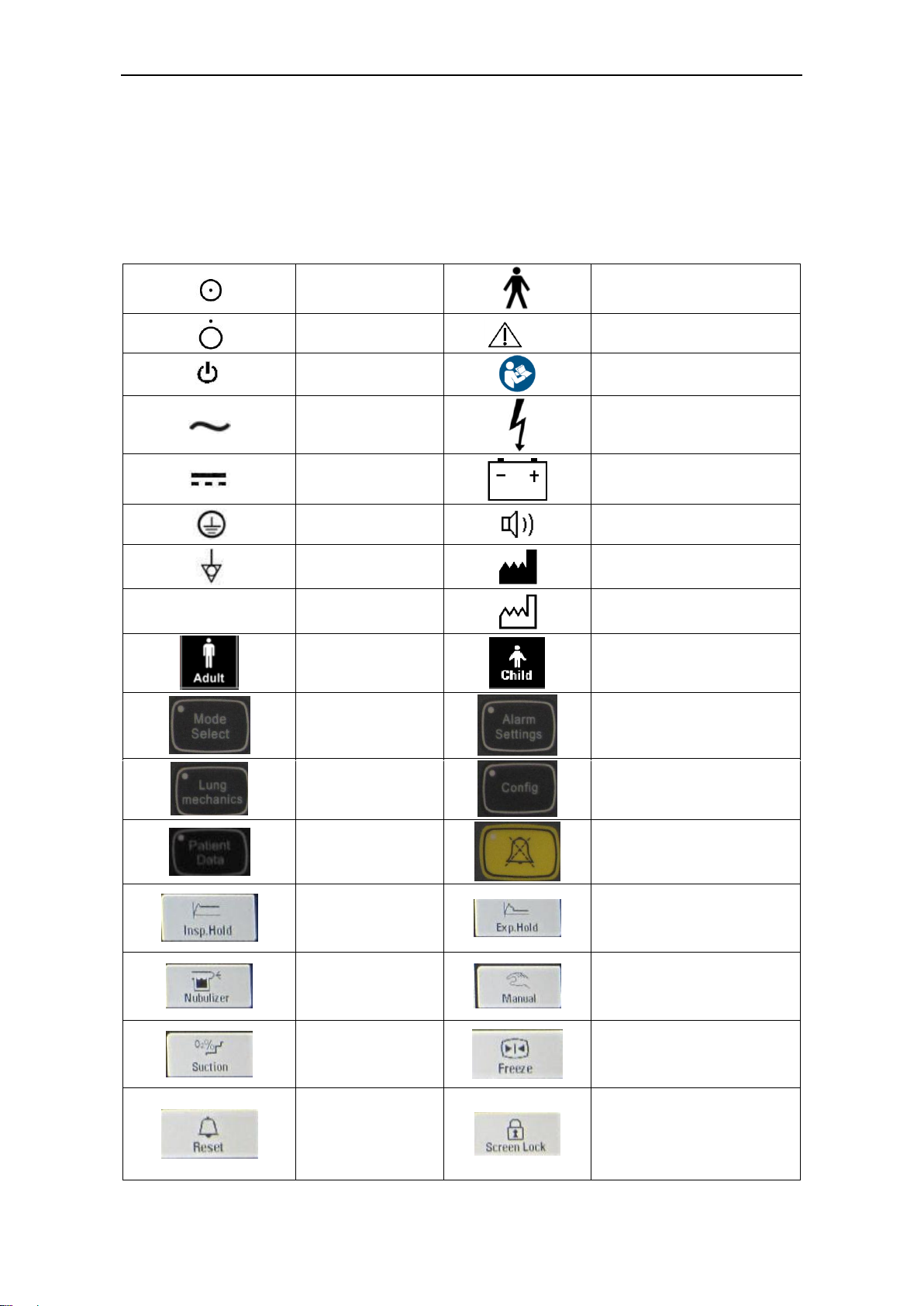
1.2 Symbols
Instead of illustrations, other symbols may also be utilized. Not all of them may necessarily
appear in the equipment and manual. The symbols include:
ON (Power)
Type B applied part
OFF (Power)
Caution
Standby
Refer to instruction
manual/booklet
Alternating
Current
Dangerous Voltage
Direct Current
Battery
Protectively earth
Buzzer
Equipotential
Manufacturer
SN
Serial Number
Date of manufacture
Adult
Child
Mode Select
Alarm Settings
Lung mechanics
Config
Patient Date
Alarm Silence Key
Inspiratory hold
Expiratory hold
Nebulization
Manual inspiration
Intelligent
increase of
oxygen
Waveform freeze
Alarm Reset
Screen Lock

1. Introduction
1–3
CE
Representative
The system, with this label
under the stipulations in
the operating manual,
complies with the
requirements related from
93/42/EEC. 0123 is the
certificate number to
certify authorizations
Humidity
limitation
Do not re-use
Fragile, handle
with care
Keep dry
Temperature
limitation
Upward
Do not roll
Stacking layers limit
1.3 Warnings and Cautions
WARNING and CAUTION indicate all the possible dangers in case of violation of
the stipulations in this manual. Refer to and follow them.
WARNING: indicates potential hazards to operators or patients.
CAUTION: indicates potential damage to equipment.
1.3.1 Warnings
WARNING: Do not use the system until you have read and understood this manual
including:
• All connections of the system
• All warnings and cautions
• Operation procedure of each and every component of the system
• Test procedure of each and every component of the system
WARNING: To ensure proper servicing and avoid the possibility of physical injury, only
qualified personnel should attempt to service or make authorized modifications to the
ventilator.
WARNING: An authorized service engineer must first install the ventilator and run
Aeonmed‟s installation procedure, which includes calibration of various system components,
before you connect a patient to the ventilator.
WARNING: 590P ventilator is not intended to be a comprehensive monitoring device and
does not activate alarms for all types of dangerous conditions for patients on life-support
equipment.

Shangrila590P Ventilator User Manual
1–4
WARNING: Patients on life-support equipment must be appropriately monitored by
competent medical personnel and suitable monitoring devices at all times.
WARNING: An alternative source of ventilation, such as manual respiratory equipment,
should always be available when using 590P ventilator.
WARNING: Ensure that inspiratory and expiratory circuits are connected to the correct
port before operation of equipment.
WARNING: The expiratory gas pathway may become contaminated with body fluids or
expired gases during normal use, and the inspiratory gas pathway may become contaminated
during fault condition, such as occlusion, breath hoses disconnection.
WARNING: Disposable breath hoses shall not be reused. Reuse of the single use hoses
can cause cross infection.
WARNING: Assure that hoses used have the appropriate resistance and compliance to
ensure proper therapy.
WARNING: Do not disconnect the cable between the Main Control Unit and the GUI
screen while Ventilator is operating.
WARNING: The ventilator must not be connected to any anti-static or electrically
conductive hoses, tubing or conduit
WARNING: Adding attachments or other components or sub-assemblies to the ventilator
breathing system can change the pressure gradient across the ventilator breathing system and
that such changes to the ventilation breathing system can affect the ventilator performance.
WARNING: Make sure gas cylinders are connected with a sufficient amount of gas and
the Battery module is functioning. Follow the hospital guidelines.
WARNING: Expiratory module is heated; use caution to avoid burns.
WARNING: Use caution when handling flammable or fragile components.
WARNING: Do not place containers of liquids (such as humidifier water reservoirs) on top
of or above ventilator. Liquids getting into the ventilator can cause equipment malfunction with
the risk of patient injury.
WARNING: To avoid risk of electric shock, this equipment must only be connected to a
supply mains with protective earth.
1.3.2 Cautions
CAUTION: If the system test fails, do not use the system. Attempt to troubleshoot and fix
the failure. If you are unable to fix the device, ask an authorized service representative to
repair the device.
CAUTION: Check the ventilator periodically as outlined in this manual; do not use if
defective. Immediately replace parts that are broken, missing, obviously worn, distorted, or
contaminated.

1. Introduction
1–5
CAUTION: Do not put ventilator into service until the patient setup is complete.
CAUTION: Measurements can be affected by mobile and RF communications equipment.
CAUTION: Do not use oxygen hoses that are worn, frayed, or contaminated by
combustible materials such as grease or oils. Textiles, oils, and other combustibles are easily
ignited and burn with great intensity in air enriched with oxygen.
CAUTION: Follow your hospital infection control guidelines for handling infectious material.
Aeonmed recognizes that cleaning, sterilization, sanitation, and disinfection practices vary
widely among health care institutions. It is not possible for Aeonmed to specify or require
specific practices that will meet all needs, or to be responsible for the effectiveness of cleaning,
sterilization, and other practices carried out in the patient care setting.
CAUTION: Equipment not suitable for use in the presence of a Flammable Anesthetic
mixture with Air or with Oxygen or Nitrous Oxide.
CAUTION: To avoid an electrical shock hazard while servicing the ventilator, be sure to
remove all power to the ventilator by disconnecting the power source and turning off all
ventilator power switches.
CAUTION: To avoid a fire hazard, keep matches, lighted cigarettes, and all other sources
of ignition (e.g., flammable anesthetics and/or heaters) away from 590P ventilator and oxygen
hoses.
CAUTION: In case of fire or aburning odor, immediately disconnect the ventilator from the
oxygen supply, facility power and backup power source.
CAUTION: During operation; do not block: Speaker Holes Cooling Fan
CAUTION: Do not use 590P Ventilator in an MRI environment.
CAUTION: The ventilator shall not be used in a hyperbaric chamber.
CAUTION: The ventilator shall not be used with helium or mixtures with helium.
CAUTION: Tip over hazard; use care when moving ventilator mounted to cart as device
could tip over leading to injury or damage of equipment.
CAUTION: Do not use sharp objects to make selections on the LCD touch screen or
panel.
CAUTION: Do not connect USB interface while the system is in service
CAUTION: The Network interface connection is for authorized Aeonmed service only.
CAUTION: Batteries should be removed if equipment will not be in service for more than 6
months. See Section 7.5 for Maintaining battery.
CAUTION: Do not immerse the oxygen sensor or the connector in any type of liquid.

Shangrila590P Ventilator User Manual
1–6
CAUTION: When ventilator is exposed to conditions outside normal operating
environments, allow 24 hours in normal environment before using.
CAUTION: Do not connect items that are not specified as part of the system.
CAUTION: When using a humidifier, user should frequently check the water trap and look
for water in the hose. If water is found in the hose, this water should be removed. Also, it is
important the water trap is positioned in a way such that it is lower than the patient tubes.
CAUTION: Connecting electrical equipment to auxiliary outlet effectively leads to creating
a medical equipment system, and can result in a reduced level of safety, make sure the ME
SYSTEM comply with requirements of IEC 60601-1:2005. The user who connects is
responsible for the standard for the requirements applicable to the medical equipment system.
CAUTION: The user of this product shall have sole responsibility for any ventilator
malfunction due to operation or maintenance performed by anyone not trained by Aeonmed.
CAUTION: Usage of a filter on the expiratory side will increase the resistance of the
patient circuit.
CAUTION: All parts of the ventilator system are suitable for use within the patient
environment.
CAUTION: All gas volume, flow, and leakage specifications in this manual are expressed
at STPD (standard temperature and pressure dry), except when specified with another
condition.
1.4 Frequently used function
(1) Power On / Off Switch
(2) Connect patient hoses and gas supply
(3) Settings
(4) Start Ventilation/Standby
(5) Monitoring data
(6) Alarm, Event/Alarm log
(7) Calibration
(8) Cleaning and disinfection
(9) Breathing Circuit Components
(10) System interconnections for gas supply
(11) Humidifier and system interconnections
(12) Nebulizer and system interconnections

1. Introduction
1–7
1.5 Definitions, Acronyms, and Abbreviations
CPAP
Continuous Positive Airway Pressure (setting)
f
Respiratory rate, i.e. breaths per minute (setting)
fspont
Respiratory rate of spontaneous breathing by the patient (monitored)
ftotal
Total respiratory rate, i.e. sum off and fspont (monitored)
FiO2
Delivered oxygen percentage (Setting and monitored data)
I : E
Inspiration to expiration time, I to E ratio, (monitored)
MV
Exhaled minute volume (monitored)
MVspont
Minute volume of spontaneous expiration by the patient (monitored)
Paw
Patient airway pressure
PEEP
Positive end expiratory pressure, it may be used to improve oxygenation of
the patient (setting and monitored data)
PINSP
Inspiratory airway pressure in PCV (setting)
Pmean
Mean airway pressure is updated every at the end of last breath cycle, i.e. a
running mean (monitored)
Ppeak
Maximum patient airway pressure during a patient breath (monitored)
Pplat
Patient airway pressure measured at the end of inspiratory pause time
(monitored)
Psens
Pressure sensitivity (setting)

Shangrila590P Ventilator User Manual
1–8
PSUPP
Pressure support (setting)
TI
Inspiration time (setting)
TP
Inspiratory pause time; increase inspiration time to facilitate increased patient
oxygenation (setting)
Vsens
Flow sensitivity (setting)
VT
Tidal volume of mechanically delivered breaths (setting)
VTE
Exhaled tidal volume (monitored)
VTI
Inhaled tidal volume (monitored)
1.6 System composition
SN
Name
Specifications
1.
Main unit
standard configuration
2.
O2 pipeline
5m
3.
Air pipeline
1m
4.
Medical air compressor
Optional
5.
Reservoir bag
Expendable, 1L
6.
Respiratory circuit
Expendable
7.
Fuse
Spare
8.
Nebulizer
Optional
9.
Humidifier
Optional
10.
Valve diaphragm
Mounted
11.
Valve plate
Mounted
12.
Cover
Attachment
13.
Filter
Expendable
14.
Hinged arm
Expendable
15.
Power cord
Expendable
16.
Water trap
Expendable
17.
Y-piece
Expendable
2. Structure
2–1
2 Structure
2.1 Front view
CAUTION: Monitoring conditions of this system: inspiratory module: ATPD (Dry
temperature and pressure) ;expiratory module: BTPS (Saturated temperature and pressure) .
WARNING: Independent means of ventilation (e.g. a self-inflating manually powered
resuscitator with mask) should be available whenever the Shangrila590P Ventilator System is
in use.
WARNING: Do not use antistatic or electrically-conductive breathing tubes and mask.
2.1.1 Front panel
Figure 2-1 Front panel of Shangrila590P
1. Display screen
In the figure 2-1, display screen has been marked with rectangle frame; it displays the most
information including alarm message, patient data, waveform monitored etc. More details refer
to section 2.1.2.

Shangrila590P Ventilator User Manual
2–2
2. Controls and indicators
Figure 2-2 Function key
Mode select
Press this key, you can select ventilation mode required.
More details refer to section 3.2 and 3.3.
Alarm settings
Press this key, you can setup alarm parameters such as
lower limit of Paw etc.
More details refer to section 3.4.
Lung mechanics
More details refer to section 3.5.
Configuration key
The operator can customize some parameters such as
language, date and time, unit of pressure etc.
Patient Date
Press this key, you can monitor patient parameters.
Alarm silence key
Alarm silence key. Turns off alarm sound for 2 minutes
except low-priority alarm. The yellow light on the alarm
silence key lights during the silence period, and turns off
if you press the alarm reset key or the 2-minute interval
times out.Anew high-urgency alarm cancels the silence.
AC power
indicator lamp
When the ventilator connected ac power, the lamp lights.
Internal battery
indicator lamp
When charging, orange lamp lights.
When supplying power, green lamp lights.
Knob
Adjusts the value of a setting.Abutton that is highlighted
means that the knob is linked to that setting. Where
applicable, turning the knob clockwise increases the
value, and turning the knob counterclockwise decreases
the value.

2. Structure
2–3
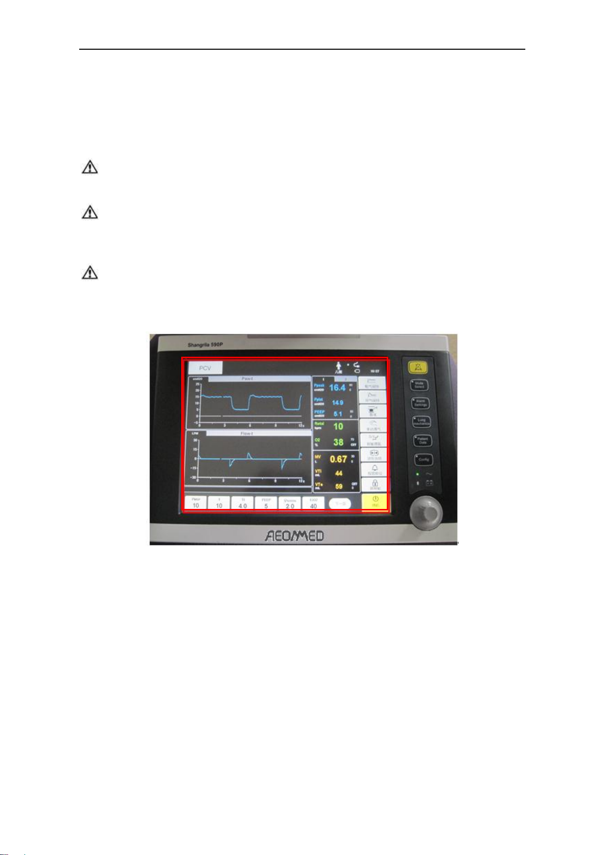
2.1.2 LCD screen
The main interface can be divided into six parts: Parameter setup area, Short Cut keys area,
Patient Measured Parameters area, Patient Waveforms area, Information area and User
Message Prompts area, as shown in Figure 2-3.
Figure 2-3 shows the actual operational screen layout of the ventilator
Figure 2-4 Main interface
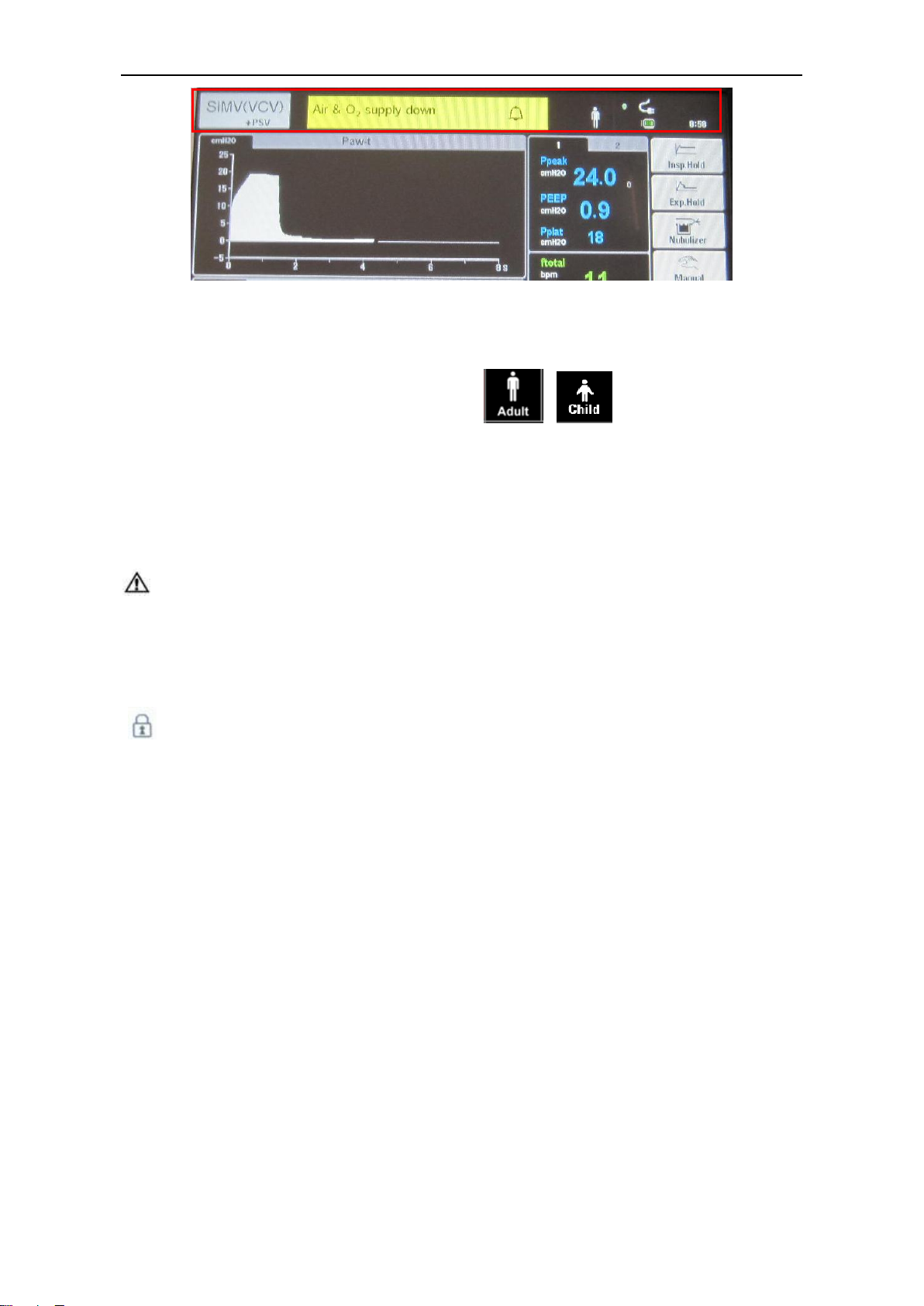
2.1.2.1 Information Area
The Information area includes seven sections: Ventilation Mode, Alarm Messages, Trigger
Patient Type, Screen Lock, AC and Battery indicators.
Shangrila590P Ventilator User Manual
2–4
Figure 2-5 Information area
Ventilation Mode area: Displays the current mode of Ventilation.
Patient Type: Displays the current patient‟s type ( or )
Alarm Messages area: When there is no alarm message, this area is same background color
as other screen areas; when a technical or functional alarm occurs, the background color will
change to either red or yellow and text information will be displayed.
Trigger area: Displays the current ventilator trigger type. There are three trigger types:
Pressure Trigger, Flow Trigger, and Manual Trigger. If there is currently no trigger in use, the
trigger symbol will disappear.
CAUTION: If the trigger sensitivity is set too high, a self-triggering (auto-triggering)
condition may be reached. Triggering will then be initiated by the system and not by the patient.
This should always be avoided by decreasing the trigger sensitivity. This is also important
during transport as the movement of the body and the breathing system may lead to false
triggering.
Screen Lock: When press the" lock "button, and then press other key is invalid, a indicator
“ ”flashes in information area.
Time area: Displays the current time. It is 24-hour format.
Battery indicators area: Displays the AC and battery connection status.
2.1.2.2 Patient Waveform Area
At center of the screen, the Patient Waveforms area is the main display area. In the default
state, this area will display two waveforms: Pressure waveform and Volume waveform. There
are two formats, block and line.

2. Structure
2–5
Figure 2-6 Patient waveform area
2.1.2.3 Patient Measured Parameters Area
This area displays all of the monitored patient parameters and it is divided into two pages.
Each page is accessed by selecting the icon 1, or 2.
Figure 2-7 Patient measured parameters area
2.1.2.4 Shortcut Keys Area
The ventilator has shortcut keys to access many ventilator operations, including Inspiratory
Hold, Expiratory Hold, Nebulizer, Manual breath delivery, Suction, Freeze, Reset, Screen Lock,
and Standby/Start Ventilation.

Shangrila590P Ventilator User Manual
2–6
Figure 2-8 shortcuts keys area
2.1.2.5 User Message Prompts Area
User message prompts area is above on the ventilation set-up area. This area is gray back
ground. Information is white.
Figure 2-9 Ventilation Parameter Set-up Area
2.1.2.6 Parameter Setup Area
The ventilation parameter setup area is at the bottom of the screen. The breathing parameters
settings necessary for the current ventilation mode are displayed in this area. See the example
as shown in Figure 2-10. If the ventilation parameter setup items for the selected Ventilation
mode do not fit in this space, the “Next”key will allow the user to access and change the other
setup items.
Table of contents
Other Aeonmed Medical Equipment manuals


Popular Medical Equipment manuals by other brands


Getinge
Getinge Arjohuntleigh Nimbus 3 Professional Instructions for use

Mettler Electronics
Mettler Electronics Sonicator 730 Maintenance manual

Pressalit Care
Pressalit Care R1100 Mounting instruction

Denas MS
Denas MS DENAS-T operating manual

bort medical
bort medical ActiveColor quick guide

AccuVein
AccuVein AV400 user manual


