Aeris Elite T3 User manual

ELITE T3
DIVE COMPUTER
OPERATING MANUAL
2
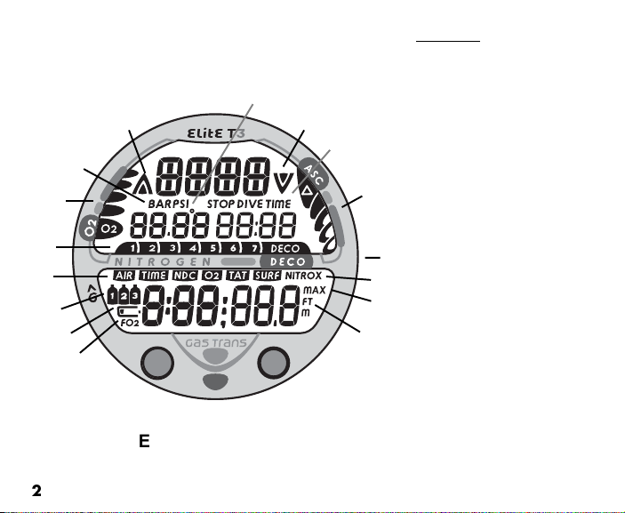
Elite T3 FULL LCD
Components:
a. Advance (A) Button
b. LED Warning Light
c. Mode/Mi (M) Button
d. Symbol - FO2
e. Icon - Low Battery
f. Icons - Tank (Gas) 1, 2, 3
g. Symbols - AIR TIME
TIME NDC
TIME O2
TIME TAT
TIME SURF
h. NIBG
i. O2BG
j. Symbol - PSI or BAR (Pressure)
k. Icon - Ascend Arrow
l. Icon - degrees (Temperature)
m. Icon - Descend Arrow
n. Symbol - STOP TIME
DIVE TIME
o. VARI
p. Select (S) Button
q. Symbol - NITROX
r. Symbol - MAX
s. Symbol - FT or M (Depth)
l
o
q
b
p
m
g
r
f
a
k
i
c
s
j
n
d
e
h

3
CONTENTS
WARRANTY, NOTICES, DECOMPRESSION MODEL ....................................................................................................7
FCC ID ............................................................................................................................................................................... 8
INTRODUCTION AND GENERAL FEATURES AND DISPLAYS .................................................................................... 9
INTERACTIVE CONTROL CONSOLE ..................................................................................................................... 10
OPERATING MODE STRUCTURE ........................................................................................................................... 11
AUDIBLE ALARM ...................................................................................................................................................... 12
SMARTGLO BACKLIGHT ........................................................................................................................................ 1
POWER SUPPLY ...................................................................................................................................................... 15
BAR GRAPHS ........................................................................................................................................................... 17
PC INTERFACE ......................................................................................................................................................... 19
SYMBOLS AND ALPHA NUMERIC GRAPHICS ...................................................................................................... 19
ALPHA / NUMERIC DISPLAYS ................................................................................................................................ 20
Tank Pressure Display .......................................................................................................................................... 20
Depth Displays ...................................................................................................................................................... 20
Air Time Remaining Display ................................................................................................................................. 20
Date. Time, and Temperature Displays ................................................................................................................ 21
FREE Dive Mode Displays ................................................................................................................................... 21
SURFACE SEQUENCE AND OPERATING MODES ..................................................................................................... 23
OPERATING MODES ................................................................................................................................................ 2
SURFACE MODE ...................................................................................................................................................... 2
NORM (Normal) Surface Main Display ................................................................................................................ 25
NORM Surface Main Button Operations .............................................................................................................. 26
Elite T3 Battery Status ....................................................................................................................................... 27
Transmitter Status .............................................................................................................................................. 27
SET MODES .............................................................................................................................................................. 28
SET F GROUP (FO2) ................................................................................................................................................ 28
Set FO2 for NORM Nitro Dives .......................................................................................................................... 29

4
CONTENTS (continued)
Set FO2 GAS 1 ..................................................................................................................................................... 31
Set FO2 GAS 2 ..................................................................................................................................................... 32
Set FO2 GAS 3 ..................................................................................................................................................... 33
Set FO2 50% Default ........................................................................................................................................... 34
SET A GROUP (NORM/GAUG ALARMS) ................................................................................................................ 3
Set Audible Alarm ................................................................................................................................................. 35
Set Depth Alarm ................................................................................................................................................... 36
Set EDT (Elapsed Dive Time) Alarm ................................................................................................................... 37
Set NIBG (Nitrogen Loading Bar Graph) Alarm ................................................................................................... 38
Set DTR (Dive Time Remaining) Alarm ................................................................................................................ 39
Set Turn Pressure Alarm (TMT1) ......................................................................................................................... 40
Set End Pressure Alarm ....................................................................................................................................... 41
Set PO2 Alarm ...................................................................................................................................................... 42
SET U GROUP (UTILITIES) ...................................................................................................................................... 3
Set Wet Activation ................................................................................................................................................ 44
Set Units of Measure ............................................................................................................................................ 45
Set NORM Safety Stop ......................................................................................................................................... 46
Set Conservative Factor ....................................................................................................................................... 47
Set Backlight Duration .......................................................................................................................................... 48
Set Sampling Rate ................................................................................................................................................ 49
Set TMT1 (Transmitter 1 Link Code) .................................................................................................................... 50
Set TMT (Transmitter) 2-3 Use ............................................................................................................................ 52
Set TMT2/BUD1 (Transmitter 2 Link Code) ........................................................................................................ 53
Set TMT3/BUD2 (Transmitter 3 Link Code) ........................................................................................................ 55
SET T GROUP (TIME/DATE) .................................................................................................................................... 57
Set Hour Format ................................................................................................................................................... 58
Set Time ................................................................................................................................................................ 58
Set Date ................................................................................................................................................................ 59
SERIAL NUMBER (Elite T3) ..................................................................................................................................... 60
NORM SURF ALT DISPLAY (SURFACE ALTERNATE) ........................................................................................... 61
NORM PLAN MODE .................................................................................................................................................. 61
FLY MODE ................................................................................................................................................................. 6
SAT MODE (DESATURATE) ..................................................................................................................................... 66

5
CONTENTS (continued)
NORM/GAUG LOG MODE ........................................................................................................................................ 67
NORM/GAUG HISTORY MODE ................................................................................................................................ 72
OVERVIEW OF DISPLAYED SYMBOLS AND ICONS ............................................................................................ 7
OVERVIEW OF DIVE MODE OPERATION ................................................................................................................... 75
POSITIONING OF THE ELITE T3 ............................................................................................................................. 77
Link Interruption Underwater ................................................................................................................................ 77
DIVE TIME REMAINING (DTR) ................................................................................................................................. 78
No Decompression Dive Time Remaining (NDC) ................................................................................................ 79
O ygen Accumulation Time Remaining (OTR) .................................................................................................... 80
Air Time Remaining (ATR) .................................................................................................................................... 80
Air Time Remaining Alarm .................................................................................................................................... 81
ASCENT RATE ALARM ............................................................................................................................................ 82
CONTROL OF DISPLAYS ......................................................................................................................................... 83
WET CONTACTS ....................................................................................................................................................... 8
NORM TYPE DIVE MODES ........................................................................................................................................... 85
NORM NO DECOMPRESSION DIVE MODE ........................................................................................................... 86
NORM Dive No Deco Safety Stop ....................................................................................................................... 89
DECOMPRESSION DIVE MODE ........................................................................................................................ 91
VIOLATION MODES .................................................................................................................................................. 95
NORM HIGH PO2 .................................................................................................................................................... 100
HIGH OXYGEN ACCUMULATION .......................................................................................................................... 101
SUMMARY OF NORM/GAUG WARNING AND ALARM MESSAGES .................................................................. 102
SWITCHING GAS MIXES AND BUDDY PRESSURE CHECK .................................................................................... 103
SWITCHING GAS MIXES (NORM ONLY) .............................................................................................................. 10
BUDDY PRESSURE CHECK (NORM ONLY) ......................................................................................................... 109
NORM POST DIVE MODES ......................................................................................................................................... 113
TRANSITION PERIOD ............................................................................................................................................ 11
AFTER THE TRANSITION PERIOD ....................................................................................................................... 116

6
CONTENTS (continued)
GAUGE OPERATING MODE ....................................................................................................................................... 117
GAUG SURFACE DISPLAYS .................................................................................................................................. 118
GAUG DIVE DISPLAYS .......................................................................................................................................... 119
FREE DIVE OPERATING MODE ................................................................................................................................. 121
FREE SURFACE DISPLAYS ................................................................................................................................... 122
FREE COUNTDOWN TIMER (CDT) ....................................................................................................................... 12
SET FREE CDT ....................................................................................................................................................... 126
SET FREE EDT (ELAPSED DIVE TIME) ALARM .................................................................................................. 127
SET FREE DEPTH ALARMS .................................................................................................................................. 128
FREE DIVE DISPLAYS ............................................................................................................................................ 132
FREE DIVE ALARMS .............................................................................................................................................. 133
ENTRY INTO DECO DURING A FREE DIVE ......................................................................................................... 136
REFERENCE ................................................................................................................................................................. 137
UPLOADING SETTINGS AND DOWNLOADING DATA ........................................................................................ 138
PC Compatibility Requirements .......................................................................................................................... 139
CARE AND CLEANING ........................................................................................................................................... 1 0
INSPECTIONS AND SERVICE ............................................................................................................................... 1 0
BATTERY REPLACEMENT .................................................................................................................................... 1 2
INSTALLING A TRANSMITTER ON A REGULATOR ............................................................................................ 1 8
TRANSMITTER COMPATIBILITY WITH NITROX .................................................................................................. 1 8
ALTITUDE SENSING AND ADJUSTMENT ............................................................................................................ 1 9
CHARTS OF NO DECOMPRESSION LIMITS AT ALTITUDE ................................................................................ 150
CHART OF OXYGEN EXPOSURE LIMITS ............................................................................................................ 151
SPECIFICATIONS ................................................................................................................................................... 152
INSPECTION/ SERVICE RECORD ......................................................................................................................... 159
Pay special attention to items marked
with this Warning symbol.
7
LIMITED TWO-YEAR WARRANTY
For details, refer to the Product Warranty Registration Card provided. Register on-line at www.diveaeris.com
COPYRIGHT NOTICE
This operating manual is copyrighted, all rights are reserved. It may not, in whole or in part, be copied, photocopied,
reproduced, translated, or reduced to any electronic medium or machine readable form without prior consent in writing
from ERIS/2002 Design.
Elite T3 Operating Manual, Doc. No. 12-7201
© 2002 Design, 2006
San Leandro, C US 94577
TRADEMARK, TRADE NAME, AND SERVICE MARK NOTICE
ERIS, the ERIS logo type, Elite T3, the Elite T3 logo, ir Time Remaining ( TR), Diver Replaceable Batteries, Graphic
Diver Interface, Nitrogen Loading Bar Graph (NIBG), Pre Dive Planning Sequence (PDPS), SmartGlo, Set Point, Control
Console, Turn Gas larm, and ERIS Computer Interface ( CI) are all registered and unregistered trademarks, trade
names, and service marks of ERIS. ll rights are reserved.
PATENT NOTICE
U.S. Patents have been issued, or applied for, to protect the following design features:
ir Time Remaining (U.S. Patent no. 4,586,136 and 6,543,444) and Data Sensing and Processing Device (U.S. Patent
no. 4,882,678). Set NIBG larm and other patents pending. User Setable Display (U.S. Patent no. 5,845,235) is
owned by Suunto Oy (Finland).
DECOMPRESSION MODEL
The programs within the Elite T3 simulate the absorption of nitrogen into the body by using a mathematical model. This
model is merely a way to apply a limited set of data to a large range of experiences. The Elite T3 dive computer model
is based upon the latest research and experiments in decompression theory.
Still, using the Elite T3, ust as using
the U.S. Navy (or other) No Decompression Tables, is no guarantee of avoiding decompression
sickness, i.e. the bends.
Every divers physiology is different, and can even vary from day to day. No machine
can predict how your body will react to a particular dive profile.

8
WAR I G: If your Elite T3 stops working for any reason while
operating as a Dive Computer, it is important that you have antici-
pated this possibility and are prepared for it. This is an important
reason for not pushing the no decompression and oxygen expo-
sure limits, and a critical reason to avoid entering decompression.
If you dive in situations where your trip would be ruined or your
safety would be jeopardized by losing the use of your Elite T3, a
backup instrument system is highly recommended.
FCC ID: MH8A
FCC COMPLIANCE:
This equipment complies with Part 15 of the FCC Rules. Operation is subject to the following two conditions: 1. this equipment may not
cause harmful interference, and 2. this equipment must accept any interference received, including interference that may cause undesired
operation.
FCC INTERFERENCE STATEMENT:
This equipment has been tested and found to comply with the limits for an Intentional Radiator, a Class B Digital Device, pursuant to Part
15 of FCC Rules, Title 47 of the Code of Federal Regulations. These rules are designed to provide reasonable protection against harmful
interference in a commercial or residential installation. This equipment generates, uses and can radiate radio frequency energy and, if
not installed and used in accordance with the instructions, may cause harmful interference to radio communications.
There is no guarantee that interference will not occur in a particular installation. If this equipment does cause interference to radio or
television reception, which can be determined by turning the equipment off and on, the user is encouraged to try to correct the
interference by one or more of the following measures:
Reorient or relocate the receiving antenna.
Increase the separation between the equipment and receiver.
Connect the equipment to an outlet on a circuit different from that to which the receiver is connected.
Consult the dealer or an experienced radio/TV technician.
Warning: Changes or modifica ions o his uni no expressly approved by AERIS/2002 Design could void
he user's au hori y o opera e he equipmen .

9
WAR I G: Prior to diving with the Elite T3,
you must also read and understand the AERIS
Dive Computer Safety and Reference Manual,
Doc. o. 12-7203, which provides Important
Warnings and Safety Recommendations as
well as general product information.
INTRODUCTION
AND
GENERAL FEATURES AND DISPLAYS

10
INTRODUCTION
Welcome to AERIS and thank you for choosing the Elite T3 !
It is extremely important that you read this Operating Manual in se uence and understand
it completely before attempting to use the Elite T3 as a dive computer.
It is e ually important that you read the AERIS Dive Computer Safety and Reference
Manual (Doc. No. 12-7203) provided with your Elite T3. It contains information that you
must become familiar with prior to diving with your Elite T3.
Remember that technology is no substitute for common sense, and a dive computer only
provides the person using it with data, not the knowledge to use it.
I TERACTIVE CO TROL CO SOLE
The Interactive Control Console consists of 3 Control Buttons that allow you to select mode
options and access specific information. They are also used to link the Transmitter(s), enter
Settings, activate the Backlight, and acknowledge the Audible Alarm.
Throughout this manual they will be referred to as the M, S, and A buttons.
Left/Front - Mode (M) button
Right/Front - Advance (A) button
Right/Side - Select (S) button
MA
S

11
OPERATI G MODE STRUCTURE
The M button is used to access 3 operating Modes (Fig. 1) that
include NORM (Normal Air/Nitrox Dive Computer), GAUG
(Digital Gauge Mode), and FREE (Free Dive Mode).
The screens of the Main Modes and Sub Modes will remain on
display until a button is pressed to access another screen or
Mode, activate a se uence, or for 2 minutes if no button is
pressed.
When Wet Activation is set On, the Elite T3 will enter the
selected Dive Mode upon descent to 5 FT (feet) /1.5 M (meters),
regardless of what surface screen is displayed at the time.
WAR I G: When Wet Activation is set OFF, the
Elite T3 must be activated by push button prior
to the first dive of a new series. Commencing a
dive will not activate Dive Mode unless Wet
Activation is set O or the unit is activated.
Entering Settings and Plan Mode are available in NORM SURF
Mode which also allows access to Battery/Transmitter Status,
Fly, Desat, Log, and History Modes. Tank Pressure is displayed
if a Transmitter is active and Linked with the Elite T3.
Fig. 1 - Operating Modes
NORM (Normal Air/Nitro )
FREE (Mode)
GAUG (Digital Gauge Mode)
12
GAUG Surface Mode allows access to Battery/Transmitter Status, Fly, Log, and History
Modes. It also displays Tank Pressure.
FREE Mode allows access to sub modes by first accessing NORM Surface Mode. It does
not display Tank Pressure.
Once a dive is made in GAUG Operating Mode, the Elite T3 is locked into that Mode for
24 hours after the dive.
The Elite T3 also features 2 modes for use of Transmitter Pressure. A setting allows you to
choose whether Transmitters 2 and 3 are for your use (SELF) or for checking 1 or 2 Bud-
dies' Tank Pressure(s). The setting remains fixed until changed in the NORM/GAUG SET
U menu.
AUDIBLE ALARM
Most warning situations that activate the Audible Alarm while operating in NORM or
GAUG Mode cause the Elite T3 to emit 1 beep per second for 10 seconds, or until the
situation is corrected, or it is acknowledged by momentarily pressing and releasing the S
button (less than 2 seconds). After being acknowledged and the situation corrected, the
Alarm will sound again upon reentry into the warning situation, or entry into another type
of warning situation.
FREE Dive Mode has its own set of Alarms which emit 3 short beeps either 1 or 3 times
which cannot be acknowledged or set Off.

13
A red LED Warning Light, located on the left side of the housing, is synchronized with the
Audible Alarm. It will flash as the Audible Alarm sounds. It will turn Off when the Alarm is
acknowledged or the situation is corrected. The Audible and LED will not be active if the
Alarm is Set OFF (a group A setting).
Situations that will activate the NORM/GAUG 10 second Alarm include -
Air T ime Remaining (ATR) at 5 minutes, then again at 0 minutes.
ATR becomes less than No Deco and O2 Time Remaining for 1 minute.
Turn Pressure at the Set Point selected (Transmitter 1).
End Pressure at the Set Point selected (active T ransmitter).
Descent deeper than the Max Depth Set Point selected.
Dive T ime Remaining at the Set Point selected.
Elapsed Dive Time at the Set Point selected.
High PO2 of 1.60 ATA or the Set Point selected.
High O2 of 300 OTU (single or daily exposure).
Nitrogen Loading Bar Graph at the segment Set Point selected.
NORM/GAUG Ascent Rate exceeds 60 FPM (18 MPM) when deeper than 60 FT (18
M), or 30 FPM (9 MPM) at 60 FT (18 M) and shallower.
Loss of the active T ransmitter Link signal for more than 15 seconds during a dive.
Entry into Decompression Mode (Deco).
Conditional Violation (above a re uired Deco Stop Depth for less than 5 minutes).
Delayed Violation (above a re uired Deco Stop Depth for more than 5 minutes).
Delayed Violation (a Deco Stop Depth greater than 60 FT/18 M is re uired).
Delayed Violation (Maximum Operating Depth of 330 FT/100 M is exceeded).
A Gas Switch to another tank would expose the diver to PO2 greater than 1.60 ATA.
14
A single short beep (which cannot be disabled) is emitted for the following -
Upon completion of a Hot Swap battery change.
Change from Delayed to Full Violation 5 minutes after the dive.
3 short beeps (which cannot be disabled) are emitted for the following -
Air T ime Remaining becomes less than No Deco and O2 Time Remaining.
FREE Dive Elapsed Dive T ime Alarm (3 beeps every 30 seconds if set On).
FREE Dive Depth Alarms 1/2/3 (set se uentially deeper) - each 3 beeps 3 times.
FREE Dive NIBG Alarm (Caution zone, 7 segments) - 3 beeps 3 times.
Entry into Deco during a FREE Dive (Permanent Violation) - 3 beeps 3 times.
Free Dive Mode Countdown Timer reaches 0:00 - 3 beeps 3 times.
During the following NORM Dive situations, the 10 second Audible Alarm will not turn off
when acknowledged -
Ascending above a re uired Decompression Ceiling Stop Depth for more than 5
minutes (referred to as a Delayed Violation).
Decompression re uires a Ceiling Stop Depth of 70 FT/21 M or deeper.
Being on the Surface for 5 minutes after a Conditional Violation.
SMARTGLO® BACKLIGHT
To activate the SmartGlo Backlight - press the S button.
If ambient light level is low, the Backlight will activate and illuminate the display for
button depression time* plus the user set Duration time of 0, 5, or 10 seconds, for a
maximum of 20 seconds.
(*The Backlight will turn Off if the button is depressed for more than 10 seconds.)
Press the button again to activate as desired.
15
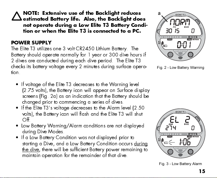
OTE: Extensive use of the Backlight reduces
estimated Battery life. Also, the Backlight does
not operate during a Low Elite T3 Battery Condi-
tion or when the Elite T3 is connected to a PC.
POWER SUPPLY
The Elite T3 utilizes one 3 volt CR2450 Lithium Battery. The
Battery should operate normally for 1 year or 300 dive hours if
2 dives are conducted during each dive period. The Elite T3
checks its battery voltage every 2 minutes during surface opera-
tion.
If voltage of the Elite T3 decreases to the Warning level
(2.75 volts), the Battery icon will appear on Surface display
screens (Fig. 2a) as an indication that the Battery should be
changed prior to commencing a series of dives.
If the Elite T3's voltage decreases to the Alarm level (2.50
volts), the Battery icon will flash and the Elite T3 will shut
Off.
Low Battery Warning/Alarm conditions are not displayed
during Dive Modes.
If a Low Battery Condition was not displayed prior to
starting a Dive, and a Low Battery Condition occurs during
the dive, there will be sufficient Battery power remaining to
maintain operation for the remainder of that dive.
Fig. 3 - Low Battery Alarm
Fig. 2 - Low Battery Warning
a

16
Transmitters use one 3 volt, CR2 Lithium Battery. A Transmitter's
battery should provide normal operation for 1 year or 300 dive
hours. Transmitters check battery voltage when they are pressur-
ized and will send a Low Battery signal to the Receiver in the
Elite T3 when the voltage drops below the Warning level.
Transmitter Low Battery Warning/Alarm conditions are only
displayed on Status screens that can be accessed while
viewing the NORM Surface Display.
To check the condition of the Elite T3 or a Transmitter's Battery if
NORM or GAUG Mode is selected, depress the S button for 2
seconds while viewing the NORM or GAUG Surface Main
Display, then release it.
As the button is depressed, the VT3's Receiver will activate.
2 seconds later, the VT3's Battery status will be displayed
for 3 seconds (Fig. 4), then -
if active and linked, T ransmitter 1's Battery status will be
displayed for 3 seconds (Fig. 5), then -
if active and linked, T ransmitter 2's Battery status will be
displayed for 3 seconds, then -
if active and linked, T ransmitter 3's Battery status will be
displayed for 3 seconds, then -
the display will then revert to Surface Mode.
If a T ransmitter is not active and linked, the message
NotA vAil (not available) will be displayed (Fig. 6).
Fig. 4 - Battery Status (Good)
Fig. 5 - Transmitter 1 Battery
Status (Good)
Fig. 6 - Transmitter 3 Status
(Not Available)

17
BAR GRAPHS
The Elite T3 features a Nitrogen Loading Bar Graph (NIBG) (Fig. 7a) that represents your
relative no decompression or decompression status.
As your Depth and Elapsed Dive Time increase, segments will add to the NIBG, and as
you ascend to shallower depths, the segments of the NIBG will begin to recede, indicating
that additional no decompression time is allowed.
The NIBG monitors 12 different nitrogen compartments simultaneously and displays the
one that is in control of your dive. It consists of 8 segments, the lower 7 represent No
Decompression status and the 8th at the top indicates a Decompression condition.
When the Elite T3 is set to operate in NORM Nitrox mode, the 5 segment O2 Bar Graph
(O2BG) (Fig. 7b) will represent oxygen accumulation.
Displays associated with oxygen and the O2 Bar Graph will be
displayed if FO2 for any Gas (1, 2, or 3) has been set at a
value other than 'Air' (e.g., a numerical value).
The O2BG will show the maximum of either per dive accumu-
lated oxygen or 24 hour period accumulated oxygen. As your
oxygen exposure (accumulation) increases during a NORM
dive, segments will add to the O2BG, and as saturation de-
creases, it will begin to recede, indicating that additional expo-
sure is allowed for that dive and 24 hour period.
Fig. 7 - NIBG and O2BG
ba
18
The Elite T3 will store oxygen accumulation calculations for up to
10 dives conducted during a 24 hour period. If the maximum
limit for NORM dive oxygen loading has been exceeded for that
day (24 hour period), all of the segments of the O2BG will be
displayed flashing.
Depth/Time values will not appear in Plan Mode until the O2BG
recedes into the normal zone (lower 4 segments) indicating that
your daily oxygen dosage has decreased an amount e uivalent
to the amount accumulated during the latest dive completed.
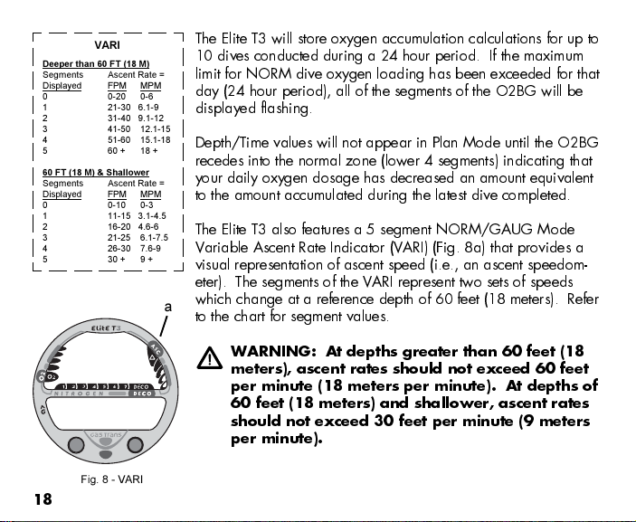
The Elite T3 also features a 5 segment NORM/GAUG Mode
Variable Ascent Rate Indicator (VARI) (Fig. 8a) that provides a
visual representation of ascent speed (i.e., an ascent speedom-
eter). The segments of the VARI represent two sets of speeds
which change at a reference depth of 60 feet (18 meters). Refer
to the chart for segment values.
WAR I G: At depths greater than 60 feet (18
meters), ascent rates should not exceed 60 feet
per minute (18 meters per minute). At depths of
60 feet (18 meters) and shallower, ascent rates
should not exceed 30 feet per minute (9 meters
per minute).
Fig. 8 - VARI
a
VARI
Deeper than 60 FT (18 M)
Segments Ascent Rate =
Displayed FPM MPM
0 0-20 0-6
1 21-30 6.1-9
2 31-40 9.1-12
3 41- 0 12.1-1
4 1-60 1 .1-18
60 + 18 +
60 FT (18 M) & Shallower
Segments Ascent Rate =
Displayed FPM MPM
0 0-10 0-3
1 11-1 3.1-4.
2 16-20 4.6-6
3 21-2 6.1-7.
4 26-30 7.6-9
30 + 9 +

19
PC I TERFACE
Interface with a PC is accomplished by connecting the Elite T3 to a PC USB Port using the
USB Interface Cable provided. The same Cable is used for Upload and Download.
The software program is on the AERIS Computer Interface CD provided, together with a
USB Driver. The program's Help section serves as the User Manual and can be printed for
personal use. The Settings Upload program is used to check the Elite T3's existing Settings
and for entering settings into the Elite T3. The Data Download program is used to retrieve
Data that was sampled during dives and stored in the Elite T3's memory.
The Elite T3 checks for an External Access re uest once every second while in Surface
Mode. Checks are not made if the unit is WET. For a connection to be made, the Inter-
face Cable is plugged into the Elite T3's Data Port and plugged into a PC USB Port. To
establish the connection, the PC program must be running. When the connection is made,
all segments of the Elite T3 appear on the display until completion of the Upload or Down-
load operation.
The Elite T3 reverts to the Surface Mode Main screen after completion of the Upload
or Download operation, or after 2 minutes if no PC action was taken.
SYMBOLS A D ALPHA UMERIC GRAPHICS
The upper line of digits on the LCD screen is used to convey alpha Messages such as Day
of the Week, Operating Modes, items being Set, Gas and Transmitter identification,
Altitude level, and Alarm identification. At times, the second line is also used to display
alpha numeric graphics such as PO2 and On/Off. The FO2 setting of a selected Gas will
appear in the lower line.

20
ALPHA / UMERIC DISPLAYS
Tank Pressure Display ( ORM/GAUG only)
When the Elite T3's Receiver is set ON and active, Tank Pres-
sure from an active Transmitter that is properly linked will be
displayed on the NORM or GAUG MAIN screens (Fig. 9a).
Values of Pressure are displayed numerically from 000 PSI (00
BAR) up to 5,000 PSI (345 BAR) in increments of 5 PSI (1 BAR).
Depth Displays (all Modes)
During dives, the
Current Depth
display (Fig. 9b) and
Maxi-
mum Depth
which is accessed as an Alternate Display (Fig.
10a) indicate Depths from 0 to 399 FT (120 M) in increments of
1 FT (.1 M).
During a No Decompression Safety Stop, the set
Stop Depth
(Fig. 11a) is displayed and during a Decompression condition,
the re uired
Ceiling Stop Depth
is displayed. These Depths
are displayed graphically on the top row of the screen with the
letters F indicating Feet and M indicating Meters (ex: 10F = 10
Foot Stop and 9M = 9 Meter Stop).
Fig. 11 - Safety Stop Display
a
Fig. 9 - Dive Main Display
b
a
Fig. 10 - Dive Alt Display
a
Table of contents
Other Aeris Diving Instrument manuals


Popular Diving Instrument manuals by other brands

Sony
Sony easydive leo R FX3 instructions

Aqua Lung
Aqua Lung SEA LV2 Technical manual

Northern Diver
Northern Diver LOCATION MARKER FLOAT 600G manual

Ocean Reef
Ocean Reef Snorkie-talkie instruction manual

momoDESIGN
momoDESIGN O.ME.R Umberto Pelizzari UP-X1 Quick Start-Up Manual

Suunto
Suunto EON STEEL 2.5 user guide


