Aeris XR1 User manual

XR1
DIVE COMPUTER
OPERATING MANUAL


3
CONTENTS
LIMITED TWO-YEAR WARRANTY ............................................................................................................................ 5
NOTICES ..................................................................................................................................................................... 5
DECOMPRESSION MODEL ....................................................................................................................................... 5
FULL DISPLAY ............................................................................................................................................................ 6
FEATURES AND DISPLAYS............................................................................................. 7
INTRODUCTION .......................................................................................................................................................... 8
CONTROL BUTTON ................................................................................................................................................... 8
BAR GRAPHS ............................................................................................................................................................. 9
Nitrogen Loading Bar Graph (NiBG) ...................................................................................................................... 9
Variable Ascent Rate Indicator (VARI) .................................................................................................................. 10
INFORMATIONAL DISPLAYS ................................................................................................................................... 10
Depth Displa s ...................................................................................................................................................... 10
Time Displa s ....................................................................................................................................................... 11
Date Displa ......................................................................................................................................................... 11
Temperature Displa ............................................................................................................................................. 11
POWER SUPPLY ...................................................................................................................................................... 12
Batter Indication ................................................................................................................................................... 12
Low Batter Condition ........................................................................................................................................... 13
DIVE TIME REMAINING ........................................................................................................................................... 1
NOTICE - WET ACTIVATION .................................................................................................................................... 16
SETUP AND ACTIVATION .............................................................................................. 17
ACTIVATION .............................................................................................................................................................. 18
SURFACE SEQUENCE ............................................................................................................................................. 19
SURFACE MODE ...................................................................................................................................................... 19
DIVE PLANNER (PLAN MODE) ............................................................................................................................... 20
SET MODE ................................................................................................................................................................ 20
PC INTERFACE ......................................................................................................................................................... 2

4
CONTENTS (continued
DIVE MODES .................................................................................................................. 25
DIVE MODE BAR GRAPHS ...................................................................................................................................... 26
CONTROL OF DISPLAYS ......................................................................................................................................... 26
NO DECOMPRESSION DIVE MODE ....................................................................................................................... 27
DECOMPRESSION DIVE MODE .............................................................................................................................. 29
VIOLATION MODES .................................................................................................................................................. 31
USER SELECTED DIGITAL GAUGE MODE ............................................................................................................ 36
POST DIVE MODES ....................................................................................................... 37
POST DIVE SURFACE MODE .................................................................................................................................. 38
TRANSITION PERIOD .............................................................................................................................................. 38
AFTER THE TRANSITION PERIOD (THE FIRST 2 HOURS) .................................................................................. 39
Time to Fl / Desaturate ....................................................................................................................................... 39
Dive Planner ......................................................................................................................................................... 40
Log Mode .............................................................................................................................................................. 40
AFTER THE FIRST 2 HOURS .................................................................................................................................. 3
RESET FEATURE......................................................................................................................................................
GENERAL ....................................................................................................................... 45
CARE AND CLEANING ............................................................................................................................................. 6
INSPECTIONS AND SERVICE ................................................................................................................................. 7
BATTERY REPLACEMENT ...................................................................................................................................... 58
ALTITUDE SAMPLING/COMPENSATION ............................................................................................................... 53
SPECIFICATIONS ..................................................................................................................................................... 5
SERVICE RECORD ................................................................................................................................................... 58
Pay special attention to items marked with this WARNING symbol.

5
LIMITED TWO-YEAR WARRANTY
For details, refer to the Product Warranty Registration Card provided.
COPYRIGHT NOTICE
This Owners Guide is copyrighted, all rights are reserved. t may not, in whole or in part, be copied, photo-
copied, reproduced, translated, or reduced to any electronic medium or machine readable form without prior
consent in writing from AER S / 2002 Design.
XR1 Operating Manual, Doc. No. 12-7197
© 2002 Design, 2005
San Leandro, CA USA 94577
TRADEMARK NOTICE
AER S, the AER S logo, XR1, and the XR1 logo are all registered and unregistered trademarks of AER S.
Those Trademarks Registered are Registered in the U.S. Patent and Trademark Office. All rights are reserved.
PATENT NOTICE
U.S. Patents have been issued, or applied for, to protect the following design features:
Dive Time Remaining (U.S. Patent no. 4,586,136), Data Sensing and Processing Device (U.S. Patent no.
4,882,678), and Ascent Rate ndicator (U.S. Patent no. 5,156,055). User Setable Display (U.S. Patent no.
5,845,235) is owned by Suunto Oy (Finland).
DECOMPRESSION MODEL
The programs within the XR1 simulate the absorption of nitrogen into the body by using a mathematical
model. This model is merely a way to apply a limited set of data to a large range of experiences. The XR1
dive computer model is based upon the latest research and experiments in decompression theory. Still, using
the XR1, just as using the U.S. Navy (or other) No Decompression Ta les, is no guarantee of avoiding de-
compression sickness, i.e. the ends. Every divers physiology is different, and can even vary from day to
day. No machine can predict how your body will react to a particular dive profile.

6
XR1 FULL LCD
Components:
a. Control Button
b. Variable Ascent Rate Indicator
c. Nitrogen Loading Bar Graph
d. Icon - Max Depth (Log Mode)
e. Icon - Temperature
f. Icon - Dive Number
g. Icon - Max Depth (Dive Mode)
h. Icon - Descend Arrow
Icon - Decompression Ceiling
Icon - Ascend Arrow
i. Icon - Log Mode
j. Icon - Depth units
k. Icon - Time
g. Batter Status Indicator
n. Icon - Operating Mode
a
b
c
d
e
f
g
h
i
k
l
j
m
7
FEATURES and DISPLAYS
WARNING: Prior to diving with the XR1, you must also read and
understand the AERIS Dive Computer Safety & Reference Manual,
Doc. No. 12-7203, which provides Important Warnings and Safety
Recommendations as well as general product information.
8
INTRODUCTION
Welcome to AERIS and thank you for choosing the XR1 !
It is extremely important that you read this O ner's Guide in se-
quence and understand it completely before attempting to use the
XR1.
Remember that technology is no substitute for common sense, and
a dive computer only provides the person using it ith data, not the
kno ledge to use it.
The XR1 has numerous features that are described throughout this
manual.
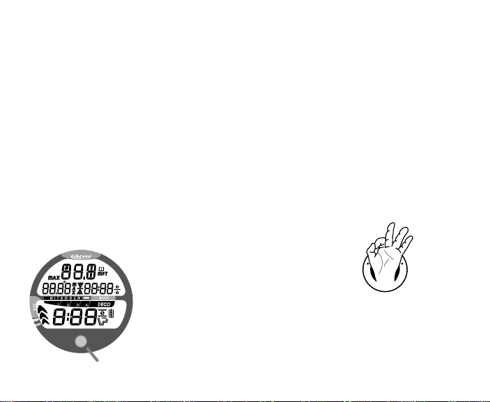
CONTROL BUTTON
The Control Button (Fig. 1) allo s you to select display options
and access specific information hen you ant to see it.
Fig. 1 - Control Button
R
E
S
P
O
N
S
I
B
L
E
D
I
V
E
R
Be a -
RESPONSIBLE DIVER
at all times.

9
BAR GRAPHS
Nitrogen Bar Graph
The Nitrogen Bar Graph (Fig. 2a) represents tissue loading of ni-
trogen, sho ing your relative no decompression or decompression
status.
The Nitrogen Bar Graph monitors 12 different nitrogen compart-
ments simultaneously and displays the one that is in control of your
dive.
As your depth and elapsed dive time increase, segments ill add to
the Graph, and as you ascend to shallo er depths, the Bar Graph
ill begin to recede, indicating that additional no decompression
time is allo ed for multilevel diving.
It is divided into a gray No Decompression (normal) zone, a yello
Caution zone (also No Decompression), and a red Decompression
(danger) zone.
While you cannot provide a guarantee against the occurrence of de-
compression sickness, you may choose your o n personal zone of
caution based upon age, physique, excessive eight, etc., to reduce
the statistical risk.
Fig. 2 - NiBG
a
10
Variable Ascent Rate Indicator (VARI
The Variable Ascent Rate Indicator (Fig. 3a) provides a visual rep-
resentation of ascent speed (i.e., an ascent speedometer). Gray is a
'normal' rate, yello a 'caution' rate, and red is 'Too Fast'. The seg-
ments of the VARI represent t o sets of speeds hich change at a
reference depth of 60 feet (18 meters). Refer to the chart for seg-
ment values.
WARNING: At depths greater than 60 feet (18 m ,
ascent rates should not exceed 60 fpm (18 mpm .
At depths of 60 feet (18 m and shallower, ascent
rates should not exceed 30 fpm (9 mpm .
INFORMATIONAL DISPLAYS
Depth Displays
During a dive, the Current Depth display (Fig. 3b), indicates
Depths from 0 to 330 feet (99.9 meters) in increments of 1 foot (.1
meter). The Depth range is extended to 399 feet (120 meters)
hen it is set to operate in Digital Gauge Mode.
By pressing the button, the Maximum Depth reached during that
dive ill be displayed (Fig. 3c).
During a Decompression Dive, the required Ceiling Stop Depth is
displayed in the Max Depth position.
Fig. 3 - VARI & Depth
a
60 feet (18 m) & Shallower
Segments Ascent Rate =
Displayed FPM MPM
0 0-10 0 - 3
1 11-25 3.5-7.5
2 26-30 -9
3 >30 >9
Deeper than 60 feet (18 m)
Segments Ascent Rate =
Displayed FPM MPM
0 0-20 0 - 6
1 21-50 6.5-15
2 51-60 15.5-1
3 >60 >1
VARI Values
b
c

11
Time Displays
Time displays are sho n in hour:minute format (i.e., 1:16 repre-
sents 1 hour and 16 minutes, not 116 minutes!). The colon that
separates hours and minutes blinks once per second hen the dis-
play is indicating real time (e.g., Elapsed Dive Time), and is solid
(non-blinking) hen times are calculated projections (e.g., Time to
Fly).
The Main Time display has the largest digits of the display (Fig.
4a) A second time display (Fig. 4b) is located above it. Both dis-
plays are identified by clock icons.
Date Display
Date is displayed only to identify dive data hile it is vie ed in
the Log Mode. When Units of Measure are set for 'Imperial', the
Month appears to the left of Day. When set for Metric, the Month
appears to the right of Day.
Temperature Display
Ambient Temperature is displayed in Surface Mode (Fig. 4c) and
Log Mode, and can be vie ed on Main Display 3 hile in a dive
mode (Fig. 5a). If the Temperature exceeds a value of '99', 2
dashes ( - - ) ill be displayed until temperature decreases to '99'.
Fig. 4 - Time Displa s &
Temperature (Surface)
a
b
Fig. 5 - Temperature
(dive mode)
c
a

12
POWER SUPPLY
The XR1 utilizes one (1) type CR 2450 Lithium 3 volt cell that
should provide approximately 300 Hours of continuous operation,
or 50 activation Periods of operation.
If you conduct 1 dive each time the unit is activated, you
should obtain approximately 50 dives.
If you conduct 3 dives each time the unit is activated, you
should obtain approximately 150 dives.
Battery Indicator
A Battery Indicator provides an indication of battery condition.
When po er is sufficient for normal unit operation (> 2.75 volts),
the full Battery icon ill be displayed solid during Surface, Plan,
and Fly, and Desat modes (Fig. 6a).
When a Lo Battery Condition is sensed (< 2.75 volts), the Indi-
cator ill only display the shell and lo er segment as a Warning.
NOTE: When the icon indicates a Low Battery
Warning condition, the Battery should be replaced
prior to conducting dives.
(continued on page 11)
Fig. 6 - Batter Indicator
a

13
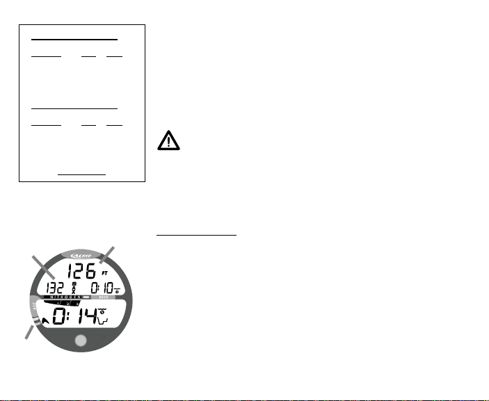
Low Battery Condition
Voltage level is checked upon activation and every 10 minutes dur-
ing operation.
If a Lo Battery Warning Condition exists (< 2.75 volts, > 2.50
volts), the Battery icon (shell and lo er segment only) ill be
displayed solid as previously described (Fig. 7a).
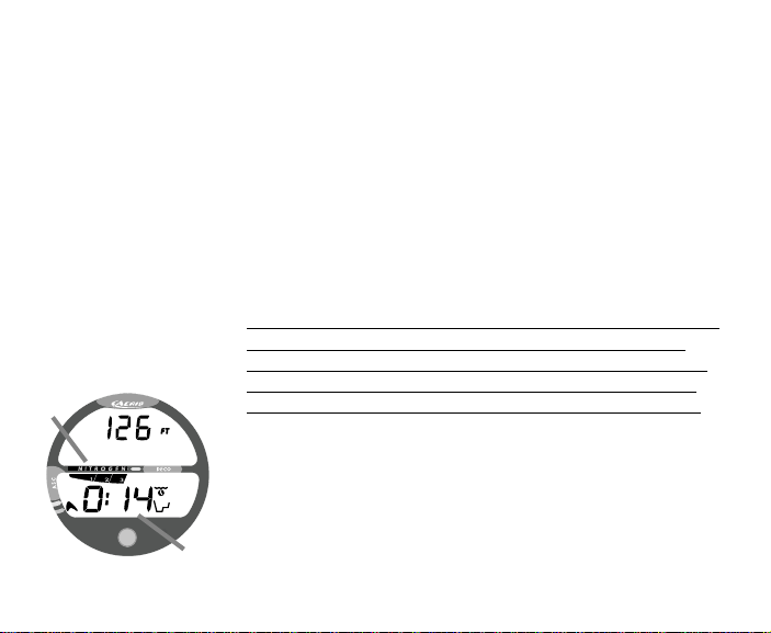
If the Battery is not changed and voltage continues to decrease
until a Lo Battery Alarm Condition exists (< 2.50 volts), the
Battery icon (shell and lo er segment only) ill flash once per
second for 5 seconds (Fig. 8a) follo ed by shutdo n of the unit.
If the button is not pressed to activate the unit prior to a dive,
and a Lo Battery Alarm Condition exists (< 2.50 volts), the
Battery icon ill appear flashing as a arning upon descent past
4 feet (1.2 meters). No other information ill be displayed.
If the unit did not display the Lo Battery icon 'prior to' entering
the Dive Mode, and a Lo Battery Condition occurs during the
dive, there ill be sufficient battery po er to maintain unit op-
eration for the remainder of 'that dive' only. The Battery icon
ill appear as a arning upon surfacing hen Surface Mode is
displayed.
When the Battery is removed, nitrogen calculations for repetitive
dives are reset to zero after 8 seconds. Also, settings such as Time
and Date must be reset. If a ne battery can be inserted ithin that
8 seconds, the calculations and settings ill be retained.
Fig. 8 - Low Batter Alarm
Fig. 7 - Low Batter Warning
a
a
14
DIVE TIME REMAINING (DTR
One of the most important pieces of information on AERIS dive computers is the 'Dive Time Re-
maining (DTR) display'. The dive computer constantly monitors no decompression status.
No Deco Dive Time Remaining (DTR
No Deco Dive Time Remaining (DTR) is the maximum amount of time that you can stay at your
present depth before entering a decompression situation. It is calculated based on the amount of
nitrogen absorbed by hypothetical tissue compartments. The rates each of these compartments ab-
sorb and release nitrogen is mathematically modeled and compared against a maximum allo able
nitrogen level. Whichever one is closest to this maximum level is the controlling compartment for
that depth. Its resulting value ill be displayed numerically (Fig. 9a) along ith the No Decom-
pression Dive icon and graphically as the Nitrogen Bar Graph (Fig. 9b).
As you ascend from depth follo ing a dive that has approached the
no decompression limit, the Nitrogen Bar Graph ill recede as
control shifts to slo er compartments. This is a feature of the de-
compression model that is the basis for multilevel diving, one of
the most important advantages that AERIS dive computers offer.
The no decompression algorithm is based upon Haldanes theory
using maximum allo able nitrogen levels developed by Merrill
Spencer. Repetitive diving control is based upon experiments de-
signed and conducted by Dr. Ray Rogers and Dr. Michael Po ell
in 1987. Diving Science and Technology® (DSAT), a corporate af-
filiate of PADI®, commissioned these experiments.
Fig. 9 - No Deco DTR
a
b

15
NOTE: Each display represents unique pieces of information.
It is imperative that you understand the formats, ranges, and values of the in-
formation represented to avoid any possible misunderstanding that could re-
sult in error.
The Informational Displays are described in detail as the various operating
modes they appear in are presented throughout this manual.
It should not be considered that the capabilities built into the XR1 provide an
implied approval or consent from AERIS for individuals to exceed the defined
limits for recreational diving, as agreed on by all internationally recognized train-
ing agencies.
The XR1 provides information based upon a personal dive profile, and therefore
must not be shared between divers. It is impossible for two divers to stay pre-
cisely together underwater, and your computer's dive profile tracking of previ-
ous dives will be pertinent to you only. Nitrogen and oxygen loading of a sec-
ond user may be significantly different and swapping dive computers could lead
to inaccurate and dangerous predictions of decompression status.
WARNINGS AND SAFETY RECOMMENDATIONS

16
The XR1 is configured ith contacts that ill automatically activate the unit hen the space be-
t een the contacts is bridged by a conductive material (immersed in ater).
The contacts are the pins of the Data Port and stem of the Push Button.
It is important that the Data Port and Button be kept clean and free of any contamination or debris
that could cause the unit to activate unnecessarily resulting in premature depletion of battery
po er.
It is also important that they be kept clean to ensure that the unit ill activate and enter dive mode
upon immersion and descent.
The Data Port and Button can be cleaned ith fresh ater and a soft bristle brush.
WARNING: The Wet Activation feature will not function unless it is Set ON (a
user setting and the contacts are bridged without interference. If the con-
tacts remain dry during a descent and an attempt is made to activate it at
depth by pressing the button or if the contacts then become wet, it will come
On briefly then shut Off and not operate in dive mode.
NOTICE
WET ACTIVATION

17
ACTIVATION AND SETUP
WARNING: Prior to diving with the XR1, you must also read and
understand the AERIS Dive Computer Safety & Reference Manual,
Doc. No. 12-7203, which provides Important Warnings and Safety
Recommendations as well as general product information.
18
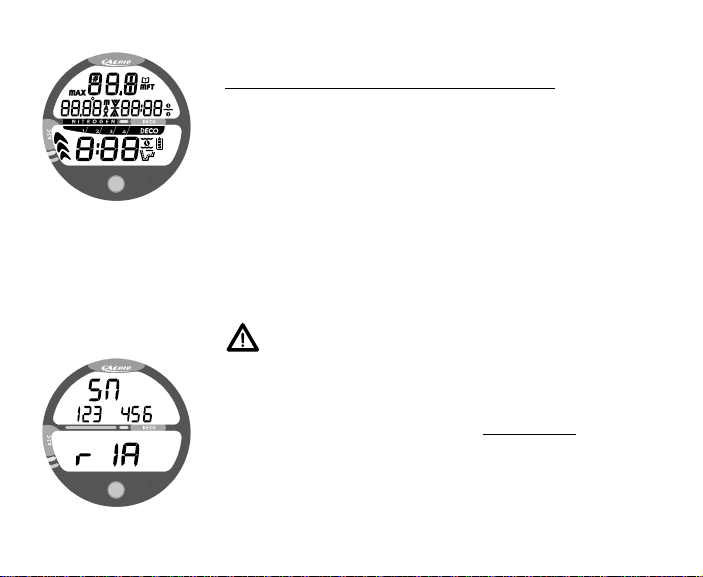
ACTIVATION
To Activate the XR1 - press and release the Button.
Upon manual activation, the unit ill enter Diagnostic Mode
(Fig. 10), displaying all segments of the LCD as 8's, follo ed by
dashes, then a countdo n from 9 to 0.
Diagnostic Mode checks the display and battery voltage to en-
sure that everything is ithin tolerance and functioning prop-
erly.
It ill also check the ambient barometric pressure, and calibrate
its present Depth as zero. At elevations of 2,000 feet (610
meters) or higher, it ill adjust its Depth readings and No De-
compression Limits for that elevation.
WARNING: If it is manually activated at elevations
higher than 14,000 feet (4,270 meters , it will per-
form a diagnostic check followed by immediate
shutdown.
To vie a screen that displays the unit's Serial Number and firm-
are revision level, hold the button depressed as the Diagnostic
countdo n reaches 00. The Serial Number screen appears (Fig. 8)
as long as the button is depressed. Upon releasing the button, the
unit shuts Off. Press and release the button to reactivate the unit
and enter Surface Mode.
Fig. 10 - Diagnostic Mode
Fig. 11 - Serial Number

19
Wet Activation (only if set O , a user setting)
The XR1 ill also automatically activate by ater contact. This is
accomplished by bridging the gap bet een contacts located on the
Button and Data Port on the side of the housing.
If no dive is made ithin 2 hours after activation, the unit ill de-
activate. If the et contacts are still et, it ill reactivate.
SURFACE SEQUENCE
While on the surface, the unit ill automatically scroll through a
Sequence of displays including -
SURFACE > FLY > SAT > PLAN
As the Surface Sequence is scrolling, you can use the button to ac-
cess Log Mode and Set Mode.
SURFACE MODE
Surface Mode information includes (Fig. 12) -
Dive Number if the module is dry (0 if no dive made yet), or the
graphic H2O if the module is et (Fig. 13)
Temperature (and degree icon and F or C graphic).
Time of Day ( ith clock icon).
Surface Interval ( ith flashing colon) and clock/ ave icon.
Battery Status icon.
Fig. 12 - Surface Mode
(module is dr )
Fig. 13 - Surface Mode
(module is wet)

20
DIVE PLANNER (PLAN MODE
The Dive Planner (Fig. 14) provides a sequence of theoretical dive
times available for depths ranging from 30 feet (9 meters) to 190
feet (57 meters) in 10 foot (3 meter) increments.
No decompression times (limits), or NDLs, are only displayed for
depths here there is at least 3 minutes of theoretical dive time
available at the depth, taking into account a descent rate of 60 feet
(18 meters) per minute.
The Dive Planner should be revie ed prior to every dive to help
you plan your dive as required to avoid exceeding no decompres-
sion limits. For repetitive dives, it indicates adjusted dive times
that are available for the next dive, based on residual nitrogen fol-
lo ing the last dive and surface interval.
WARNING: The available dive times provided by
the Dive Planner are only predictions. Depending
on cylinder size and air consumption rate you may
have less time available than indicated because of
those or other limitations.
SET MODE
After gaining access to Set Mode, settings can be made in sequence
one after the other, or you can access a specific item that you ant
to set, bypassing others.
Fig. 14 - Dive Planner
NDLs at Sea Level
(no dive made yet)
Depth NDL
FT (M) hr:mins
30 (9) :20 ( : 3)
0 (12) 2:17 (2:2 )
50 (15) 1:21 (1:25)
60 (18) :57 (:59)
70 (21) : 0 (: 1)
80 (2 ) :30 (:32)
90 (27) :2 (:25)
100 (30) :19 (:20)
110 (33) :16 (:17)
120 (36) :13 (:1 )
130 (39) :11 (:11)
1 0 ( 2) :09 (:09)
150 ( 5) :08 (:08)
160 ( 8) :07 (:07)
170 (51) :07 (:06)
180 (5 ) :06 (:06)
190 (57) :05 (:05)
Table of contents
Other Aeris Diving Instrument manuals


Popular Diving Instrument manuals by other brands

Sony
Sony easydive leo R FX3 instructions

Aqua Lung
Aqua Lung SEA LV2 Technical manual

Northern Diver
Northern Diver LOCATION MARKER FLOAT 600G manual

Ocean Reef
Ocean Reef Snorkie-talkie instruction manual

momoDESIGN
momoDESIGN O.ME.R Umberto Pelizzari UP-X1 Quick Start-Up Manual

Suunto
Suunto EON STEEL 2.5 user guide


