Aeris XR2 User manual

XR2
DIVE COMPUTER
OPERATING MANUAL

2
LIMITED TWO-YEAR WARRANTY
For details, refer to the Product Warranty Registration Card provided.
COPYRIGHT NOTICE
This Operating Manual is copyrighted, all rights are reserved. It may not, in hole or in part, be copied, pho-
tocopied, reproduced, translated, or reduced to any electronic medium or machine readable form ithout prior
consent in riting from AERIS / 2002 Design.
XR2 Operating Manual, Doc. No. 12-7195
© 2002 Design, 2005
San Leandro, CA USA 94577
TRADEMARK NOTICE
AERIS, the AERIS logo, XR2, and the XR2 logo are all registered and unregistered trademarks of AERIS.
Those Trademarks Registered are Registered in the U.S. Patent and Trademark Office. All rights are reserved.
PATENT NOTICE
U.S. Patents have been issued, or applied for, to protect the follo ing design features:
Dive Time Remaining (U.S. Patent no. 4,586,136), Data Sensing and Processing Device (U.S. Patent no.
4,882,678), and Ascent Rate Indicator (U.S. Patent no. 5,156,055). User Setable Display (U.S. Patent no.
5,845,235) is o ned by Suunto Oy (Finland).
DECOMPRESSION MODEL
The programs ithin the XR2 simulate the absorption of nitrogen into the body by using a mathematical
model. This model is merely a ay to apply a limited set of data to a large range of experiences. The XR2
dive computer model is based upon the latest research and experiments in decompression theory. Still, using
the XR2, just as using the U.S. Navy (or other) No Decompression Ta les, is no guarantee of avoiding de-
compression sickness, i.e. the ends. Every divers physiology is different, and can even vary from day to
day. No machine can predict ho your body ill react to a particular dive profile.

3
CONTENTS
WARRANTY ................................................................................................................................................................. 2
NOTICES ..................................................................................................................................................................... 2
DECOMPRESSION MODEL ....................................................................................................................................... 2
FULL LCD LAYOUT .................................................................................................................................................... 6
FEATURES AND DISPLAYS ............................................................................................. 7
CONTROL BUTTONS ................................................................................................................................................. 9
BAR GRAPHS ............................................................................................................................................................. 9
Nitrogen Bar Graph ................................................................................................................................................ 9
Oxygen (O2) Bar Graph ....................................................................................................................................... 10
Variable Ascent Rate ndicator ............................................................................................................................. 10
INFORMATIONAL DISPLAYS ................................................................................................................................... 11
Depth Displays ...................................................................................................................................................... 11
Time and Date Displays ....................................................................................................................................... 11
Temperature Display ............................................................................................................................................. 12
AUDIBLE ALARM ...................................................................................................................................................... 13
LED WARNING INDICATOR ..................................................................................................................................... 14
BACKLIGHT .............................................................................................................................................................. 14
POWER SUPPLY ...................................................................................................................................................... 15
Battery ndicator ................................................................................................................................................... 15
Low Battery Condition .......................................................................................................................................... 16
FO2 MODE ................................................................................................................................................................ 17
FO2 50% Default .................................................................................................................................................. 18
DI E TIME REMAINING ........................................................................................................................................... 19
ACTIVATION AND SETUP .............................................................................................. 21
ACTI ATION .............................................................................................................................................................. 22
SURFACE MODE ...................................................................................................................................................... 23
SET MODES .............................................................................................................................................................. 24
ENTER NG SETT NGS -SET MODE #1 .............................................................................................................. 25
ENTER NG SETT NGS -SET MODE #2 .............................................................................................................. 29

4
RESET (CLEAR) FEATURE ........................................................................................... 42
PRE DIVE PLAN MODE ................................................................................................. 43
DI E PLANNER ......................................................................................................................................................... 44
DIVE MODES .................................................................................................................. 47
DI E MODE BAR GRAPHS ...................................................................................................................................... 48
CONTROL OF DISPLAYS ......................................................................................................................................... 48
NO DECOMPRESSION DI E MODE ....................................................................................................................... 49
DECOMPRESSION DI E MODE .............................................................................................................................. 52
IOLATION MODES .................................................................................................................................................. 55
Conditional Violation ............................................................................................................................................. 56
Delayed Violation 1/2/3 ......................................................................................................................................... 57
mmediate Violation Mode and Violation Gauge Mode ........................................................................................ 58
HIGH PO2 .................................................................................................................................................................. 60
HIGH OXYGEN ACCUMULATION ............................................................................................................................ 61
USER SET DIGITAL GAUGE MODE ........................................................................................................................ 63
POST DIVE MODES ....................................................................................................... 65
POST DI E SURFACE MODE .................................................................................................................................. 66
TRANSITION PERIOD .............................................................................................................................................. 66
AFTER THE TRANSITION PERIOD (THE FIRST 2 HOURS) .................................................................................. 68
To access the Dive Planner (Plan Mode) ............................................................................................................. 68
To access the Time to Fly Countdown ................................................................................................................. 69
To access the Time to Desaturate Countdown .................................................................................................... 70
LOG MODE .......................................................................................................................................................... 70
AFTER THE FIRST 2 HOURS .................................................................................................................................. 73
WET ACTI ATION CONTACTS ................................................................................................................................73
DOWNLOADING DATA TO A PC .............................................................................................................................. 73
CONTENTS (con inued)

5
SIMULATOR (DEMO) MODE .......................................................................................... 75
CARE, MAINTENANCE, AND SERVICE ........................................................................ 81
CARE AND CLEANING ............................................................................................................................................. 82
INSPECTIONS AND SER ICE ................................................................................................................................. 83
BATTERY REPLACEMENT ...................................................................................................................................... 84
REFERENCE ................................................................................................................... 89
ALTITUDE SAMPLING/COMPENSATION ............................................................................................................... 90
SPECIFICATIONS ........................................................................................................... 92
SERVICE RECORD ........................................................................................................ 99
CONTENTS (con inued)
Pay special a en ion o i ems marked wi h his Warning symbol.

6
FULL LCD LAYOUT
Components:
a. Advance (Front) Button
b. Red Alarm Light
c. VAR
d. NiBG
e. con - Max Depth (Dive)
f. con - Temperature
g. con - Max Depth (Log)
h. con - Set Alarm
i. con - Dive Number
j. con - Log Mode
k. con - Depth Units
l. con - Demo Mode
m. con - Ascend Arrow
con - Deco Ceiling Bar
con - Descend Arrow
n. con - Time
o. Select (Side) Button
p. con - Battery Status
q. O2BG
r. con - Operating Mode
a
b
c
d
e
f
g
h
ij
k
l
m
n
o
p
q
r
7
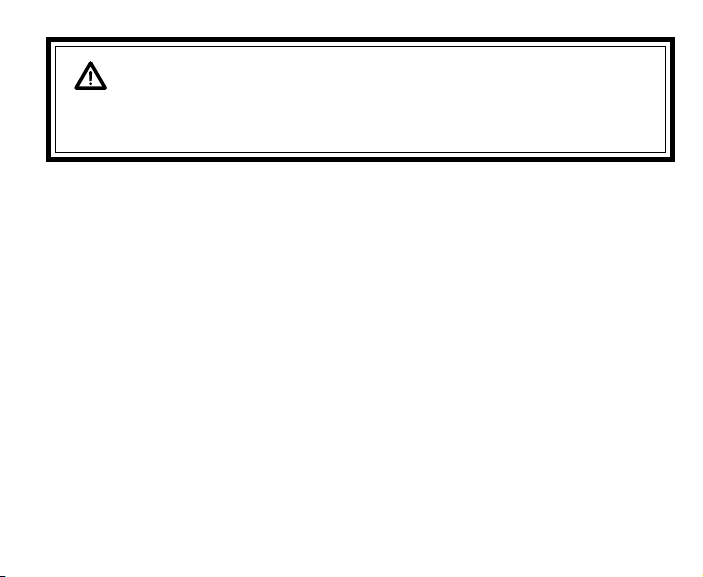
FEATURES and DISPLAYS
WARNING: Prior o diving wi h he XR2, you mus also read and
unders and he AERIS Dive Compu er Safe y & Reference Manual,
Doc. No. 12-7203, which provides Impor an Warnings and Safe y
Recommenda ions as well as general produc informa ion.

8
WELCOME TO AERIS !
AND
THANK YOU FOR CHOOSING THE XR2 !
Your XR2 presents the information that you need before, during, and after your air (or nitrox)
dives using a combination of easy to read displays and identification icons. It can also be set to
operate simply as a digital depth gauge timer. This instructional guide is intended to help you be-
come familiar with the functions and features available and show you examples of displays that
you could expect to see in the various operational modes. Relax and read through the complete
owner's guide.
Remember that the rules you learned in your basic scuba certification course(s) still apply to the
diving you will do while using a dive computer - some will become even more important. Tech-
nology is no substitute for common sense, and a dive computer only provides the person using it
with data, not the knowledge to use it.
Since the XR2 can be used when diving with either Air or Nitrox, the term Breathing Gas is used
in this manual.
Breathing Gas is the gaseous mixture breathed during a dive.
Air is a breathing gas that contains approximately 21% oxygen and 79% nitrogen (nature's
common nitrogen-oxygen mixture).
Nitrox is a nitrogen-oxygen breathing gas that contains a higher fraction of oxygen (22 to 50%)
than air.

9
CONTROL BUTTONS
The two Control Buttons allow you to select display options, access specific information when
you want to see it, and activate the Backlight.
The Front button is named Advance (Fig. 1a) and the Side button Select (Fig. 1b).
BAR GRAPHS
Ni rogen Bar Graph
The Nitrogen Bar Graph (Fig. 1c) represents tissue loading of nitrogen, showing your relative No
Decompression or Decompression status. As your Depth and Elapsed Dive Time increase, seg-
ments will add to the Graph, and as you Ascend to shallower depths, the Bar Graph will begin to
recede, indicating that additional No Decompression Time is allowed for multilevel diving.
The Nitrogen Bar Graph monitors 12 different nitrogen compart-
ments simultaneously and displays the one that is in control of your
dive. It is divided into a gray No Decompression (normal) zone, a
yellow Caution zone (also No Decompression), and a red Decom-
pression (danger) zone.
While you cannot provide a guarantee against the occurrence of de-
compression sickness, you may choose your own personal zone of
caution based upon age, physique, excessive weight, etc., to reduce
the statistical risk.
Fig. 1 - Buttons and NiBG
a
b
c
10
Oxygen (O2) Accumula ion Bar Graph
The O2 Bar Graph (Fig. 2a) represents Oxygen Loading, your rela-
tive oxygen tolerance dosage (OTU), showing the maximum of ei-
ther per dive accumulated Oxygen, or 24 hour period accumulated
Oxygen. As your accumulation increases during the dive, seg-
ments will add to the Bar Graph, and as loading decreases, it will
begin to recede, indicating that additional exposure is allowed.
NOTE: Displays associa ed wi h Oxygen and he
O2 Bar Graph will only appear if FO2 has been se
a a value o her han 'Air' (e.g., a numerical value).
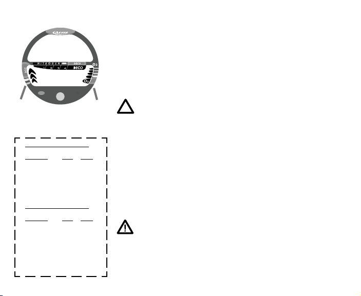
Variable Ascen Ra e Indica or
The Variable Ascent Rate Indicator (Fig. 2b) provides a visual rep-
resentation of Ascent Speed (i.e., an ascent speedometer). Gray is
a 'normal' rate, yellow a 'caution' rate, and red is 'Too Fast'. The
segments of the Variable Ascent Rate Indicator represent 2 sets of
speeds which change at a reference depth of 60 feet (18 meters).
Refer to the chart for segment values.
WARNING: A dep hs grea er han 60 fee (18
me ers), Ascen Ra es should no exceed 60 fee
per minu e (18 mpm). A dep hs of 60 fee (18
me ers) and shallower, Ascen Ra es should no
exceed 30 fee per minu e (9 me ers per minu e).
Fig. 2 - O2BG & VAR
Variable Ascent Rate ndicator
Deeper than 60 feet (18 m)
Segments Ascent Rate =
Displayed FPM MPM
0 0-20 0 - 6
1 21-30 6.5-9
2 31- 0 9.5-12
3 1-50 12.5-15
51-60 15.5-18
5 >60 >18
60 feet (18 m) & Shallower
Segments Ascent Rate =
Displayed FPM MPM
0 0-10 0 - 3
1 11-15 3.5- .5
2 16-20 5-6
3 21-25 6.5-7.5
26-30 8-9
5 >30 >9
a
b

11
INFORMATIONAL DISPLAYS
Each numeric and graphic display represents a unique piece of information. It is imperative
that you understand the formats, ranges, and values of the information represented to avoid
any possible misunderstanding that could result in error.
Dep h Displays
During a dive, the Current Depth display (Fig. 3a), indicates Depths from 0 to 330 feet (99.9
meters) in 1 foot (.1 meter) increments. The Ma imum Depth reached during that dive will be
displayed with the MAX icon (Fig. 3b).
When the unit is set to operate as a digital depth gauge timer (referred to as User Set Gauge
Mode), the Depth Display range is 'extended' to 399 feet (120 meters). At depths greater than
99.9 meters, it will indicate metric values in increments of 1 meter.
During a Decompression Dive, the required Ceiling Stop Depth is
displayed in the lower window. Maximum Depth can then be
viewed by pressing the Advance (Front) button.
Time and Da e Displays
Time displays are shown in hour:minute format (i.e., 1:22 repre-
sents 1 hour and 22 minutes, not 122 minutes!). The colon that
separates hours and minutes blinks once per second when the dis-
play is indicating real time (e.g., Elapsed Dive Time), and is solid
(non-blinking) when times are calculated projections (e.g., Time to
Fly). Fig. 3 - Depth Displays
a
b

12
Due to the importance of the information it presents, the Main
Time display (Fig. 4a) is configured with the largest segments of
the LCD. Another time display (Fig. 4b) provides additional infor-
mation. Both are identified by clock icon.
Date is displayed only to identify dive data while it is viewed in
the Log Mode.
When Units of Measure are set for 'Imperial', the Month ap-
pears to the left of Day. When set for Metric, the Month ap-
pears to the right of Day.
Tempera ure Display
Ambient Temperature is displayed (Fig. 5a) while in the Surface
Mode and can be viewed as part of an Alternate Display when the
Advance (Front) button is pressed while in a dive mode. If the
Temperature exceeds a value of '99', 2 dashes ( - - ) will be dis-
played on the screen until the unit's temperature decreases to '99'.
NOTE: The Informa ional Displays are described
in de ail as he various opera ing modes hey ap-
pear in are presen ed hroughou his manual.
Fig. 4 - Time Displays
Fig. 5 - Temperature
b
a
a

13
AUDIBLE ALARM
When warning situations activate the Alarm, the unit will emit a continuous tone for 10 seconds,
or until the situation is corrected, or it is acknowledged by pressing the Advance (Front) button
for 2 seconds. If acknowledged by the user and the situation corrected, the Alarm will sound
again upon reentry into the warning situation, or entry into another type of warning situation.
Warning situations that will sound the Alarm, if it is turned ON (a user setting), include -
Entry into Decompression Mode
PO2 => the Max PO2 Alarm (a user setting), or => 1.60 ATA.
Descent deeper than the Max Depth Alarm (a user setting).
Nitrogen Bar Graph Alarm (a user setting).
Dive Time Remaining Alarm (a user setting).
Elapsed Dive Time Alarm (a user setting).
O2 Accumulation => allowable per dive limit, or limit for a 24 hour period.
Ascending above a required Decompression stop depth for < 5 min. (Conditional Violation).
Ascent rate exceeds 60 fpm (18 mpm) if > 60 ft (18 m), or 30 fpm (9 mpm) if <= 60 ft (18 m).
The following situations initiate the Alarm, which will not turn OFF when acknowledged,
even if it was user Set OFF -
Above a required Decompression stop depth for more > 5 min. (Delayed Violation).
Decompression requires a ceiling stop depth => 70 FT (21 M).
Being on the surface for 5 minutes after a Conditional Violation (Permanent Violation).
A single short beep (which cannot be disabled) is emitted after the Diagnostic check, upon auto-
matic return to Surface Mode from Simulator Mode, upon completion of a fast battery change
with calculations settings saved, and upon change from Delayed to Full Violation after that dive.

14
LED WARNING INDICATOR
The red LED Warning Light located on the lower left portion of
the module (Fig. 6) is synchronized with the Audible Alarm and
will flash while an Alarm sounds.
The LED will be OFF when the Alarm is acknowledged, or Set
OFF (a user setting).
BACKLIGHT
To activate the Backlight while on the Surface Mode -
press the Select (Side) button for 2 seconds.
To activate the Backlight during a dive-
press and release the Select (Side) button < 2 seconds.
The screens will be illuminated for button depression time plus
0, 5, or 10 seconds (a user setting). Press the button again to ac-
tivate as desired.
The Backlight illuminates both the upper and lower screens.
It does not operate during a Low Battery condition, while on the
surface and during a dive.
Fig. 6 - LED Warning
NOTE: AERIS
recommends ha
you always carry
primary and
backup dive
ligh s when con-
duc ing dives
ha could in-
clude low ligh
si ua ions.

15
POWER SUPPLY
The XR2 utilizes one (1) type CR 2450 Lithium 3 volt cell that
should provide approximately 300 Hours of continuous operation,
or 50 activation Periods of operation.
If you conduct 1 dive each time the unit is activated, you
should obtain approximately 50 dives.
If you conduct 3 dives each time the unit is activated, you
should obtain approximately 150 dives.
Ba ery Indica or
A Battery Indicator provides an indication of battery condition.
When power is sufficient for normal unit operation (> 2.5 volts),
the Indicator (icon) will be displayed solid during Surface, Plan,
Fly, and Desat modes (Fig. 7a).
The Indicator will not be displayed during dive modes.
When a Low Battery Condition is sensed (< 2.5 volts), the Indica-
tor will flash.
(continued on page 16)
Fig. 7 - Battery ndicator
a

16
Low Ba ery Condi ion
Voltage level is checked upon activation and every 10 minutes dur-
ing operation.
If a Low Battery Condition exists when the unit is activated (by
pressing the button), the Battery icon will appear flashing once
per second for 5 seconds (Fig. 8) followed by shutdown of the
unit.
If the button is not pressed to activate the unit prior to a dive,
and a Low Battery Condition exists, the Low Battery icon will
appear flashing as a warning upon descent past 4 feet (1.2
meters). No other information will be displayed.
If the unit did not display the Low Battery icon 'prior to' entering
the Dive Mode, and a Low Battery Condition occurs during the
dive, there will be sufficient battery power to maintain unit op-
eration for the remainder of 'that dive'. The Low Battery icon
will appear upon surfacing when Surface Mode is displayed.
When the Battery is removed, nitrogen and oxygen calculations for
repetitive dives are reset to zero after 8 seconds. Also, settings
such as Time, Date, and FO2 must be reset. If a new battery can be
inserted within 8 seconds, the calculations and settings will be re-
tained.
NOTE: Ba ery change procedures are described
on page 84 of his manual.
Fig. 8 - Low Battery

17
FO2 MODE
After Activation, the XR2 will operate as an AIR computer without
displaying information associated with oxygen calculations, unless
it is set for a percentage of oxygen (FO2) other than AIR (numeri-
cal value between 21 and 50 %).
NOTE: Se ing FO2 is described on Page 27.
When set with an FO2 value of AIR (Fig. 9), the XR2 will per-
form calculations the same as if FO2 were set for 21% oxygen, in-
ternally accounting for oxygen loading for any subsequent Nitrox
dives. However, oxygen related displays, warnings, and the O2 bar
graph will not appear on the display for that dive, or subsequent
dives, unless FO2 is set for a numerical value (21 to 50).
Once a dive is made with the unit set as a nitrox computer (FO2 set
for a numerical value), the unit cannot be programmed to operate
as an AIR computer until 24 hours after the last dive. AIR will not
be displayed as an option in the FO2 Mode. However, you can set
FO2 for 21% for use with AIR.
When FO2 is set at a value of 21% (Fig. 10), the unit will remain
set at 21% for subsequent nitrox dives until FO2 is set to a higher
value, or until it automatically turns off and is reactivated.
Fig. 9 - FO2 set for A R
Fig. 10 - FO2 set for 21%

18
WARNING: The percen age of oxygen (FO2) in he
ni rox mix being used mus be se 'before each'
ni rox dive, unless he FO2 50% Defaul fea ure has
been urned OFF.
FO2 50% DEFAULT
If the Default is set to ON and FO2 is set to a value 'greater than
21%', the FO2 set point value will automatically revert to 50% 10
minutes after that dive (Fig. 11). The Maximum Depth that can be
achieved with a PO2 of 1.60 ATA will also be displayed.
FO2 must therefore be reset for each repetitive nitrox dive, or
the value will automatically 'default' to 50(%) and the dives will
be calculated based on 50% O2 (50% nitrogen) for oxygen cal-
culations and 21% O2 (79% nitrogen) for nitrogen calculations.
WARNING: If you surface for grea er han 10 min-
u es during a dive, a subsequen descen will be
considered a new dive and FO2 mus be rese .
If the Default is set to OFF, the FO2 value for repetitive dives re-
mains the same (Fig. 12) until the set point is manually changed.
WARNING: Even if he Defaul is se o OFF, he
FO2 se poin should be 'verified' o ma ch he FO2
in he ni rox mix being used before each ni rox
dive.
Fig. 11 - FO2 Default ON
Fig. 12 - FO2 Default OFF

19
DIVE TIME REMAINING
One of the most important pieces of information on Aeris dive
computers is the 'Dive Time Remaining numeric display'. The dive
computer constantly monitors no decompression status and oxygen
exposure.
The Dive Time Remaining* display will indicate the time that
is more critical for you at that particular moment (i.e.; which-
ever time is the least amount available). The specific time being
displayed is identified by the No Decompression Dive Time icon,
or the O2 Time icon.
(* This unique feature has been granted U.S. Patent No. 4,586,136.
No Decompression Dive Time Remaining
No Decompression Dive Time Remaining is the maximum amount
of time that you can stay at your present depth before entering a de-
compression situation. It is calculated based on the amount of ni-
trogen absorbed by hypothetical tissue compartments. The rates
each of these compartments absorb and release nitrogen is math-
ematically modeled and compared against a maximum allowable
nitrogen level. Whichever one is closest to this maximum level is
the controlling compartment for that depth. Its resulting value will
be displayed numerically (Fig. 13a) along with the No Decompres-
sion Dive icon and graphically as the Nitrogen Bar Graph (Fig.
13b). Fig. 13 - No Decompression
Dive Time Remaining
a
b

20
As you ascend from depth following a dive that has approached the
no decompression limit, the Nitrogen Bar Graph will recede as
control shifts to slower compartments. This is a feature of the de-
compression model that is the basis for multilevel diving, one of
the most important advantages that Aeris dive computers offer.
The no decompression algorithm is based upon Haldanes theory
using maximum allowable nitrogen levels developed by Merrill
Spencer. Repetitive diving control is based upon experiments de-
signed and conducted by Dr. Ray Rogers and Dr. Michael Powell
in 1987. Diving Science and Technology® (DSAT), a corporate af-
filiate of PADI®, commissioned these experiments.
Oxygen Accumula ion Time Remaining
Oxygen accumulation (exposure) during a dive, or 24 hour period,
appears graphically as the Oxygen Accumulation (O2) Bar Graph
(Fig. 14a). As time remaining before reaching the oxygen expo-
sure limit decreases, segments are added to the O2 Bar Graph.
When the amount of time remaining before reaching the oxygen
limit becomes less than the No Decompression Dive Time Remain-
ing, calculations for that depth will be controlled by oxygen. Oxy-
gen Time Remaining will then appear as the main numeric time
display (Fig. 14b). As oxygen accumulation continues to increase,
the O2 Bar Graph will enter the yellow Caution Zone.
Fig. 14 - O2 Accumulation
Dive Time Remaining
a
b
Table of contents
Other Aeris Diving Instrument manuals


