Aeris Epic User manual

EPIC
WATCH
DIVE COMPUTER
OPERATING MANUAL
2
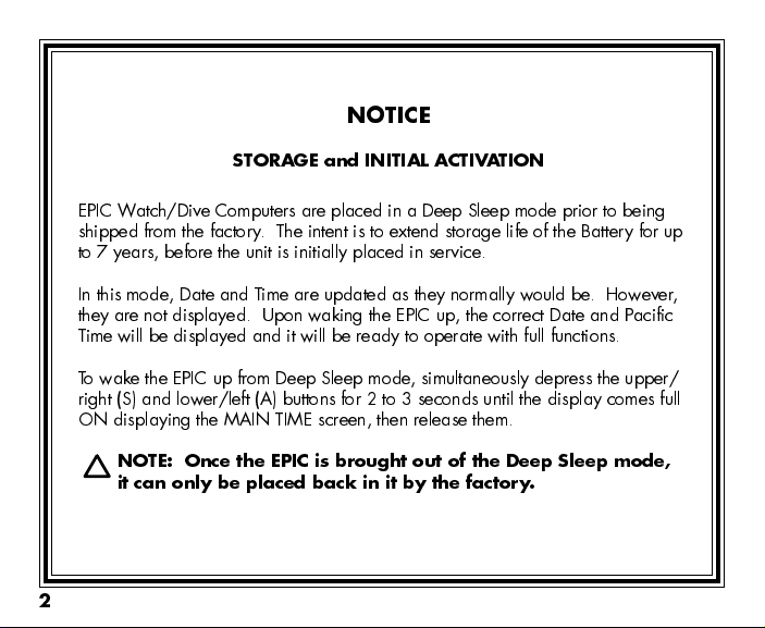
EPIC Watch/Dive Computers are placed in a Deep Sleep mode prior to being
shipped from the factory. The intent is to extend storage life of the attery for up
to 7 years, before the unit is initially placed in service.
In this mode, Date and T ime are updated as they normally would be. However,
they are not displayed. Upon waking the EPIC up, the correct Date and Pacific
Time will be displayed and it will be ready to operate with full functions.
To wake the EPIC up from Deep Sleep mode, simultaneously depress the upper/
right (S) and lower/left (A) buttons for 2 to 3 seconds until the display comes full
ON displaying the MAIN TIME screen, then release them.
NOTE: Once the EPIC is brought out of the Deep Sleep mode,
it can only be placed bac in it by the factory.
NOTICE
STORAGE and INITIAL ACTIVATION

3
CONTENTS
WARRANTY, NOTICES, DECOMPRESSION MODEL ....................................................................................................7
FULL DISPLAY ................................................................................................................................................................. 8
INTRODUCTION AND GENERAL FEATURES AND DISPLAYS .................................................................................... 9
INTERACTIVE CONTROL CONSOLE ..................................................................................................................... 10
OPERATING MODE STRUCTURE ........................................................................................................................... 11
OPERATION AS A DIVE COMPUTER ...................................................................................................................... 12
PC INTERFACE ......................................................................................................................................................... 13
SYMBOLS AND ALPHA NUMERIC GRAPHICS ...................................................................................................... 13
AUDIBLE ALARM ...................................................................................................................................................... 1
BACKLIGHT .............................................................................................................................................................. 16
POWER SUPPLY ...................................................................................................................................................... 16
WATCH FEATURES AND DISPLAYS ............................................................................................................................ 19
LOCAL DEFAULT TIME ............................................................................................................................................ 20
MAIN TIME................................................................................................................................................................. 21
SET MAIN TIME ......................................................................................................................................................... 22
ALTERNATE TIME ..................................................................................................................................................... 25
SET ALTERNATE TIME ............................................................................................................................................. 26
COUNTDOWN TIMER ............................................................................................................................................... 27
SET COUNTDOWN TIMER ...................................................................................................................................... 28
CHRONOGRAPH ...................................................................................................................................................... 29
DAILY ALARM ........................................................................................................................................................... 31
SET DAILY ALARM .................................................................................................................................................... 32
DIVE COMPUTER FEATURES AND DISPLAYS ........................................................................................................... 33
BAR GRAPH .............................................................................................................................................................. 3
ALPHA / NUMERIC DISPLAYS ................................................................................................................................ 36
Tank Pressure Displa .......................................................................................................................................... 36
Depth Displa s ...................................................................................................................................................... 36
Time and Date Displa s ....................................................................................................................................... 37
Temperature Displa ............................................................................................................................................. 38

4
CONTENTS (continued)
DIVE COMPUTER SURFACE SEQUENCE AND OPERATING MODES ...................................................................... 39
SURFACE MODE ...................................................................................................................................................... 0
Normal Surface Main Displa ............................................................................................................................... 41
Normal Surface Main Button Operations ............................................................................................................. 43
EPIC Battery Status ............................................................................................................................................
Transmitter Status .............................................................................................................................................. 5
Normal Surface Secondar Displa ..................................................................................................................... 45
Normal Surface Alternate Displa ........................................................................................................................ 46
NORMAL AND GAUGE SURFACE SET MODES .................................................................................................... 7
SET F GROUP (FO2) ................................................................................................................................................ 7
Set FO2 for NORM Nitrox Dives .......................................................................................................................... 48
Set FO2 GAS 1 ..................................................................................................................................................... 50
Set FO2 GAS 2 ..................................................................................................................................................... 51
Set FO2 GAS 3 ..................................................................................................................................................... 52
Set FO2 50% Default ........................................................................................................................................... 53
SET A GROUP (NORM/GAUG ALARMS) ................................................................................................................ 5
Set Audible Alarm ................................................................................................................................................. 55
Set Depth Alarm ................................................................................................................................................... 56
Set EDT (Elapsed Dive Time) Alarm ................................................................................................................... 57
Set NIBG (Nitrogen Loading Bar Graph) Alarm ................................................................................................... 58
Set DTR (Dive Time Remaining) Alarm ................................................................................................................ 59
Set Turn Pressure Alarm (TMT1) ......................................................................................................................... 60
Set End Pressure Alarm ....................................................................................................................................... 61
Set PO2 Alarm ...................................................................................................................................................... 62
SET U GROUP (UTILITIES) ...................................................................................................................................... 63
Set Wet Activation ................................................................................................................................................ 64
Set Units of Measure ............................................................................................................................................ 65
Set NORM Safet Stop ......................................................................................................................................... 66
Set Conservative Factor ....................................................................................................................................... 67
Set Backlight Duration .......................................................................................................................................... 68
Set Sampling Rate ................................................................................................................................................ 69

5
CONTENTS (continued)
Set TMT1 (Transmitter 1 Link Code) .................................................................................................................... 70
Set TMT (Transmitter) 2-3 Use ............................................................................................................................ 72
Set TMT2 (Transmitter 2 Link Code) ................................................................................................................... 73
Set TMT3 (Transmitter 3 Link Code) ................................................................................................................... 75
SERIAL NUMBER (EPIC) ......................................................................................................................................... 77
NORM (Normal Dive) PLAN MODE ......................................................................................................................... 78
FLY MODE ................................................................................................................................................................. 81
SAT MODE (NORM) .................................................................................................................................................. 82
NORM/GAUG LOG MODE ........................................................................................................................................ 83
HISTORY MODE (NORM/GAUG) ............................................................................................................................ 87
OVERVIEW OF DIVE MODE INFORMATION ............................................................................................................... 91
POSITIONING OF THE EPIC .................................................................................................................................... 93
Link Interruption Underwater ................................................................................................................................ 93
DIVE TIME REMAINING (DTR) ................................................................................................................................. 9
No Decompression Dive Time Remaining (NDC) ................................................................................................ 95
Ox gen Accumulation Time Remaining (OTR) .................................................................................................... 96
Air Time Remaining (ATR) .................................................................................................................................... 96
Air Time Remaining Alarm .................................................................................................................................... 97
VARIABLE ASCENT RATE ....................................................................................................................................... 98
ELAPSED DIVE TIME ............................................................................................................................................... 99
CONTROL OF DISPLAYS ......................................................................................................................................... 99
NORM TYPE DIVE MODES (AIR/NITROX) ................................................................................................................. 101
WET CONTACTS ..................................................................................................................................................... 102
NORM NO DECOMPRESSION DIVE MODE ......................................................................................................... 103
NORM Dive No Deco Safet Stop ..................................................................................................................... 106
DECOMPRESSION DIVE MODE ............................................................................................................................ 107
VIOLATION MODES ................................................................................................................................................ 111
HIGH PO2 ................................................................................................................................................................ 116
HIGH OXYGEN ACCUMULATION .......................................................................................................................... 117
SUMMARY OF WARNING AND ALARM MESSAGES .......................................................................................... 118

6
CONTENTS (continued)
SWITCHING GAS MIXES AND BUDDY PRESSURE CHECK ....................................................................................119
SWITCHING GAS MIXES (NORM ONLY) .............................................................................................................. 120
BUDDY PRESSURE CHECK (NORM ONLY) ......................................................................................................... 125
NORM POST DIVE MODES ......................................................................................................................................... 129
TRANSITION PERIOD ............................................................................................................................................ 130
AFTER THE TRANSITION PERIOD ....................................................................................................................... 131
GAUGE OPERATING MODE ....................................................................................................................................... 133
GAUG SURFACE DISPLAYS .................................................................................................................................. 13
GAUG DIVE DISPLAYS .......................................................................................................................................... 135
FREE DIVE OPERATING MODE ................................................................................................................................. 137
FREE SURFACE DISPLAYS ................................................................................................................................... 138
FREE COUNTDOWN TIMER (CDT) ....................................................................................................................... 1 0
SET FREE CDT ....................................................................................................................................................... 1 2
SET FREE ALARMS (EDT, FDA) ............................................................................................................................ 1 3
FREE DIVE DISPLAYS ............................................................................................................................................ 1 8
REFERENCE ................................................................................................................................................................. 153
UPLOADING SETTINGS AND DOWNLOADING DATA ........................................................................................ 15
CARE AND CLEANING ........................................................................................................................................... 156
INSPECTIONS AND SERVICE ............................................................................................................................... 156
BATTERY REPLACEMENT .................................................................................................................................... 158
INSTALLING A TRANSMITTER ON A REGULATOR ............................................................................................ 16
TRANSMITTER COMPATIBILITY WITH NITROX .................................................................................................. 16
ALTITUDE SENSING AND ADJUSTMENT ............................................................................................................ 165
CHARTS OF NO DECOMPRESSION LIMITS AT ALTITUDE ................................................................................ 166
CHART OF OXYGEN EXPOSURE LIMITS ............................................................................................................ 167
SPECIFICATIONS ................................................................................................................................................... 168
INSPECTION/ SERVICE RECORD ......................................................................................................................... 17
7
LIMITED TWO-YEAR WARRANTY
For details, refer to the Product Warranty Registration Card provided. Register on-line at www.OceanicWorldwide.com
COPYRIGHT NOTICE
This operating manual is copyrighted, all rights are reserved. It may not, in whole or in part, e copied, photocopied,
reproduced, translated, or reduced to any electronic medium or machine reada le form without prior consent in writing
from AERIS / 2002 Design.
EPIC Operating Manual, Doc. No. 12-7199
© 2002 Design, 2006
San Leandro, CA USA 94577
TRADEMARK, TRADE NAME, AND SERVICE MARK NOTICE
AERIS, the AERIS logotype, EPIC, the EPIC logo, Air Time Remaining (ATR), Diver Replacea le Batteries, Graphic Diver
Interface, Nitrogen Loading Bar Graph (NIBG), Planning Sequence, Set Point, Control Console, Turn Gas Alarm, and
AERIS Computer Interface are all registered and unregistered trademarks , trade names, and service marks of AERIS.
All rights are reserved.
PATENT NOTICE
U.S. Patents have een issued, or applied for, to protect the following design features:
Air Time Remaining (U.S. Patent no. 4,586,136 and 6,543,444) and Data Sensing and Processing Device (U.S. Patent
no. 4,882,678). Set NIBG Alarm and other patents pending. User Seta le Display (U.S. Patent no. 5,845,235) is
owned y Suunto Oy (Finland).
DECOMPRESSION MODEL
The programs within the EPIC simulate the a sorption of nitrogen into the ody y using a mathematical model. This
model is merely a way to apply a limited set of data to a large range of experiences. The EPIC dive computer model is
ased upon the latest research and experiments in decompression theory.
Still, using the EPIC, just s using the
U.S. N vy (or other) No Decompression T bles, is no gu r ntee of voiding decompression sick-
ness, i.e. the bends.
Every divers physiology is different, and can even vary from day to day. No machine can
predict how your ody will react to a particular dive profile.
8
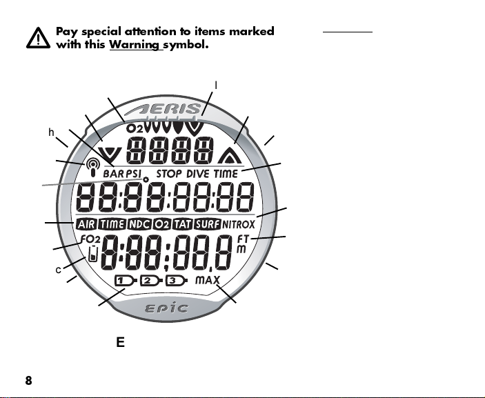
EPIC FULL LCD
Components:
a. Icons - Tank 1, 2, 3
b. Advance (A) Button
c. Icon - Low Batter
d. S mbol - FO2
e. S mbols -AIR TIME
TIME NDC
TIME O2
TIME TAT
TIME SURF
f. Icon - degrees (Temperature)
g. Icon - Dail Alarm, or -
Transmitter Link
h. Mode (M) Button
i. S mbol - PSI or BAR (Pressure)
j. Icon - Descend Arrow
k. Icon - indicates O2BG
l. Bar Graph
m. Icon - Ascend Arrow
n. Select (S) Button
o. S mbol - STOP TIME
DIVE TIME
p. S mbol - NITROX (Mode)
q. S mbol - FT or M (Depth)
r. Light (L) Button
s. S mbol - MAX
i
o
s
b
e
k
jm
n
q
r
g
d
a
p
Pay special attention to items mar ed
with this Warning symbol.
f
h
l
c

9
WARNING: Prior to diving with the EPIC, you
must also read and understand the AERIS Dive
Computer Safety and Reference Manual, Doc.
No. 12-7203, which provides Important Warn-
ings and Safety Recommendations as well as
general product information.
INTRODUCTION
AND
GENERAL FEATURES AND DISPLAYS
10
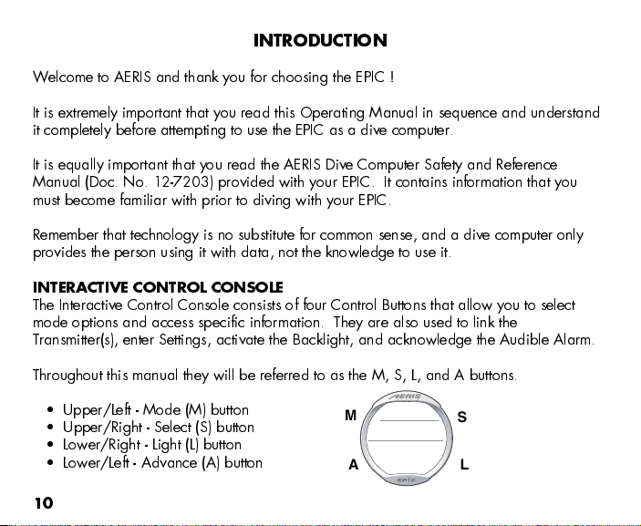
INTRODUCTION
Welcome to AERIS and thank you for choosing the EPIC !
It is extremely important that you read this Operating Manual in sequence and understand
it completely before attempting to use the EPIC as a dive computer.
It is equally important that you read the AERIS Dive Computer Safety and Reference
Manual (Doc. No. 12-7203) provided with your EPIC. It contains information that you
must become familiar with prior to diving with your EPIC.
Remember that technology is no substitute for common sense, and a dive computer only
provides the person using it with data, not the knowledge to use it.
INTERACTIVE CONTROL CONSOLE
The Interactive Control Console consists of four Control uttons that allow you to select
mode options and access specific information. They are also used to link the
Transmitter(s), enter Settings, activate the acklight, and acknowledge the Audible Alarm.
Throughout this manual they will be referred to as the M, S, L, and A buttons.
Upper/Left - Mode (M) button
Upper/Right - Select (S) button
Lower/Right - Light (L) button
Lower/Left - Advance (A) button
M
A
S
L

11
OPERATING MODE STRUCTURE
Unless it is operating in Dive Computer mode, the EPIC will be
ON in the default WATCH MAIN TIME (home time) mode (Fig.
1), like a standard WATCH, until the Mode is changed.
The M button is used to access 4 other Modes that include
Alternate Time Mode, Countdown Timer, Chronograph (stop
watch/lap timer), and Daily Alarm. It is also used to revert to
the Local Default Time display and access Computer Modes.
The screens of the Main Modes and Sub Modes will remain on
display until a button is pressed to access another screen or
Mode, activate a sequence, or for 2 minutes if no button is
pressed. The Chronograph remains on display as long as it is
running unless another Mode is accessed.
When Wet Activation is set On, the EPIC will enter selected Dive
Mode upon descent to 5 FT (feet)/1.5 M (meters), regardless of
what operating Mode it is in.
WARNING: When Wet Activation is set OFF, the
EPIC must be in Dive Surface Mode (NORM<
GAUG, or FREE prior to the first dive of a new
series. Commencing a dive while in Watch
modes will not activate Dive Mode unless Wet
Activation is set ON.
Main Sequence
(while at home)
Main Time
Alternate Time
Countdown Timer
Chronograph
Daily Alarm
Alternate Sequence
(at a travel location)
Alternate Time
Main Time (home)
Countdown Timer
Chronograph
Daily Alarm
Fig. 1 - MAIN TIME

12
OPERATION AS A DIVE COMPUTER
The EPIC features 3 Dive Computer (DC) Operating Modes,
NORM (Fig. 2A) which is used for Air and Nitrox dives, GAUG
(Fig. 2 ) used for dives in which Nitrogen-Oxygen calculations
are not performed, and FREE (Fig. 2C) used for activities that do
not use SCU A.
Entering Settings and Plan Mode are only available in NORM
SURF Mode which also allows access to attery/Transmitter
Status, Fly, Desat, Log, and History Modes. Tank Pressure is
displayed if a Transmitter is active and Linked with the EPIC.
GAUG Mode only allows access to attery/Transmitter Status,
Fly, Log, and History Modes. It also displays Tank Pressure.
FREE Mode only allows access to EPIC attery Status, Log, and
History Modes. It does not display Tank Pressure.
Once a dive is made in GAUG Operating Mode, the EPIC is
locked into that Mode for 24 hours after the dive.
The EPIC also features 2 modes for use of Transmitter Pressure.
A setting allows you to choose whether Transmitters 2 and 3 are
for your use (SELF) or for checking 1 or 2 uddies' Tank
Pressure(s). The setting remains fixed until changed in the
NORM/GAUG SET U menu.
Fig. 2 - DC MODES
2A
2B
2C
13
PC INTERFACE
Interface with a PC is accomplished by connecting the EPIC to a PC US Port using the
US Interface Cable provided. The same Cable is used for Upload and Download.
The software program is on the CD provided, together with a US Driver. The program's
Help serves as the user manual and can be printed for personal use. The Settings Upload
program is used to check the EPIC's existing Settings and for entering Time, Alarm, and
Dive Computer settings into the EPIC. The Data Download program is used to retrieve
Data that was sampled during dives and stored in the EPIC's memory.
The EPIC checks for an External Access request once every second while in the Watch
Main Time. Checks are not made if the unit is WET. For a connection to be made, the
Interface Cable is clipped onto the EPIC's Data Port and plugged into a PC US Port. To
establish the connection, the PC program must be running. When the connection is made,
all segments of the EPIC appear on the display until completion of the Upload or Down-
load operation.
The EPIC reverts to the W atch Main Time screen after completion of the Upload or
Download operation, or after 2 minutes if no PC action was taken.
SYMBOLS AND ALPHA NUMERIC GRAPHICS
The upper line of digits on the LCD screen is used to convey alpha Messages such as Day
of the Week, Operating Modes, items being Set, Gas and Transmitter identification,
Altitude level, and Alarm identification. At times, the second line is also used to display
alpha numeric graphics such as PO2 and On/Off. The FO2 setting of a selected Gas will
appear in the lower line.
14
AUDIBLE ALARM
Most warning situations that activate the Audible Alarm while operating in NORM or
GAUG Mode cause the EPIC to emit 1 beep per second for 10 seconds, or until the
situation is corrected, or it is acknowledged by momentarily pressing and releasing the S
button (less than 2 seconds). After being acknowledged and the situation corrected, the
Alarm will sound again upon reentry into the warning situation, or entry into another type
of warning situation.
FREE Dive Mode has its own set of Alarms which emit 3 short beeps either 1 or 3 times
which cannot be acknowledged or set Off.
A red LED Warning Light, located on the left side of the housing, is synchronized with the
Audible Alarm. It will flash as the Audible Alarm sounds. It will turn Off when the Alarm is
acknowledged or the situation is corrected. The Audible and LED will not be active if the
Alarm is Set OFF (a group A setting).
Situations that will activate the NORM/GAUG 10 second Alarm include -
Air T ime Remaining (ATR) at 5 minutes, then again at 0 minutes.
ATR becomes less than No Deco and O2 Time Remaining for 1 minute.
Turn Pressure at the Set Point selected (Transmitter 1).
End Pressure at the Set Point selected (active T ransmitter).
Descent deeper than the Max Depth Set Point selected.
Dive T ime Remaining at the Set Point selected.
Elapsed Dive Time at the Set Point selected.
High PO2 of 1.60 AT A or the Set Point selected.
High O2 of 300 OTU (single or daily exposure).

15
Nitrogen Loading ar Graph at the segment Set Point selected.
NORM/GAUG Ascent Rate exceeds 60 FPM (18 MPM) when deeper than 60 FT (18
M), or 30 FPM (9 MPM) at 60 FT (18 M) and shallower.
Loss of the active T ransmitter Link signal for more than 15 seconds during a dive.
Entry into Decompression Mode (Deco).
Conditional Violation (above a required Deco Stop Depth for less than 5 minutes).
Delayed Violation (above a required Deco Stop Depth for more than 5 minutes).
Delayed Violation (a Deco Stop Depth greater than 60 FT/18 M is required).
Delayed Violation (Maximum Operating Depth of 330 FT/100 M is exceeded).
A Gas Switch to another tank would expose the diver to PO2 greater than 1.60 ATA.
A single short beep (which cannot be disabled) is emitted for the following -
Upon completion of a Hot Swap battery change.
Change from Delayed to Full Violation 5 minutes after the dive.
3 short beeps (which cannot be disabled) are emitted for the following -
NORM/GAUG Ascent Rate is 51 to 60 FPM (15.1 to 18 MPM) when deeper than
60 FT (18 M), or 26 to 30 FPM (7.5 to 9 MPM) at 60 FT (18 M) and shallower.
Air T ime Remaining becomes less than No Deco and O2 Time Remaining.
FREE Dive Elapsed Dive T ime Alarm (3 beeps every 30 seconds if set On).
FREE Dive Depth Alarms 1/2/3 (set sequentially deeper) - each 3 beeps 3 times.
FREE Dive NI G Alarm (Caution zone, 4 segments) - 3 beeps 3 times.
Entry into Deco during a FREE Dive (Permanent Violation) - 3 beeps 3 times.
Watch Daily Alarm reaches time set (disabled during Dive Modes).
Watch or Free Dive Mode Countdown Timer reaches 0:00 - each 3 beeps 3 times.
16
During the following NORM Dive situations, the 10 second continuous tone will be fol-
lowed by a 5 second steady beep that will not turn off when acknowledged -
Ascending above a required Decompression Ceiling Stop Depth for more than 5
minutes (referred to as a Delayed Violation).
Decompression requires a Ceiling Stop Depth of 70 FT/21 M or deeper.
eing on the Surface for 5 minutes after a Conditional Violation (Permanent
Violation).
BACKLIGHT
To activate the acklight - press the L button.
The acklight will activate and illuminate the display for button depression time* plus
the user set Duration time of 0, 5, or 10 seconds, for a maximum of 20 seconds.
(*The acklight will turn Off if the button is held depressed for more than 10
seconds.)
Press the button again to activate as desired.
NOTE: Extensive use of the Bac light reduces estimated Battery life.
Also, the Bac light does not operate during a Low EPIC Battery Condi-
tion or when the EPIC is connected to a PC.
POWER SUPPLY
The EPIC (Watch) utilizes one 3 volt CR2430 Lithium attery. When used as a Dive
Computer, the EPIC's battery should operate normally for 1 year or 300 dive hours if 2
dives are conducted during each dive period. The EPIC checks its battery voltage every 2
minutes during surface operation.

17
If voltage of the EPIC decreases to the Warning level (2.75
volts), the attery icon will appear on Surface display
screens (fig. 3a) as an indication that the attery should be
changed prior to commencing a series of dives.
If the EPIC's voltage decreases to the Alarm level (2.50
volts), the attery icon will flash and the message CHNG >
ATT will scroll at the top of the display (Fig. 4). Operation
will automatically revert to Main Time Mode. The EPIC
would then only operate in Watch modes until the attery
becomes completely depleted.
Low attery Warning/Alarm conditions are not displayed
during Dive Modes.
If a Low attery Condition was not displayed prior to
starting a Dive, and a Low attery Condition occurs during
the dive, there will be sufficient attery power remaining to
maintain operation for the remainder of that dive.
Transmitters use one 3 volt, CR2 Lithium attery. A Transmitter's
battery should provide normal operation for 1 year or 300 dive
hours. Transmitters check battery voltage when they are pressur-
ized and will send a Low attery signal to the Receiver in the
EPIC when the voltage drops below the Warning level.
Transmitter Low attery Warning/Alarm conditions are only
displayed on Status screens that can be accessed while
viewing the NORM Surface Display.
Fig. 4 - LOW BATTERY
ALARM
Fig. 3 - LOW BATTERY
WARNING
a

18
To check the condition of the EPIC or a Transmitter's attery if
NORM or GAUG Mode is selected, depress the S button for 2
seconds while viewing the NORM, GAUG, or FREE Surface
Main Display, then release it.
As the button is depressed, the ATOM's Receiver will
activate, if in NORM or GAUG Mode.
2 seconds later, the EPIC's attery status will be displayed
for 3 seconds (Fig. 5), then -
if active and linked, Transmitter 1's attery status will be
displayed for 3 seconds (Fig. 6A), then -
if active and linked, Transmitter 2's attery status will be
displayed for 3 seconds, then -
if active and linked, Transmitter 3's attery status will be
displayed for 3 seconds, then -
the display will then revert to Surface Mode.
If a T ransmitter is not active and linked, the message
NotA vAil (not available) will be displayed (Fig. 6 ).
Tank Pressure (described later) will also appear on the active
Transmitters attery Status displays.
NOTE: If Transmitter 2-3 Use is set for BUD
(Buddy Pressure Chec ), Battery Status of those
Transmitters is not displayed (only Pressure).
Fig. 5 - BEPIC BATT GOOD
Fig. 6B - TMT 3
(Not Available)
Fig. 6A - TMT 1 BATT LOW

19
WATCH
FEATURES AND DISPLAYS
WARNING: Prior to diving with the EPIC, you
must also read and understand the AERIS Dive
Computer Safety and Reference Manual, Doc.
No. 12-7203, which provides Important Warn-
ings and Safety Recommendations as well as
general product information.
20
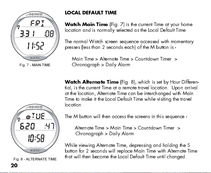
LOCAL DEFAULT TIME
Watch Main Time
(Fig. 7) is the current Time at your home
location and is normally selected as the Local Default Time.
The normal Watch screen sequence accessed with momentary
presses (less than 2 seconds each) of the M button is -
Main T ime > Alternate T ime > Countdown T imer >
Chronograph > Daily Alarm
Watch Alternate Time
(Fig. 8), which is set by Hour Differen-
tial, is the current Time at a remote travel location. Upon arrival
at the location, Alternate Time can be interchanged with Main
Time to make it the Local Default Time while visiting the travel
location.
The M button will then access the screens in this sequence -
Alternate T ime > Main Time > Countdown Timer >
Chronograph > Daily Alarm
While viewing Alternate Time, depressing and holding the S
button for 2 seconds will replace Main Time with Alternate Time
that will then become the Local Default Time until changed.
Fig. 7 - MAIN TIME
Fig. 8 - ALTERNATE TIME
Table of contents
Other Aeris Diving Instrument manuals


