AERMEC RTE240 User manual

RTE units –User manual
0412-6180480 Rev.00
RTE
240-400

User manual RTE
Page 2 of 25 0412-6180480 Rev.00

.
User manual RTE
Page 3 of 25 0412-6180480 Rev.00
1 INDEX
• Index page 3
• Purpose page 4
• Use of the device page 4
• Responsibilities and residual risks page 4
• WEEE Directive page 4
• DIAGRAM of the parameter masks page 5
• User interface page 7
• Switching on and off page 9
• Modifying the SET-POINT page 11
• Selection of the function mode page 12
• Time slots page 13
• Alarm diagnostics page 17
1
2
3
4
5
6
7
8
9
10
11
12

.
User manual RTE
Page 4 of 25 0412-6180480 Rev.00
2 PURPOSE
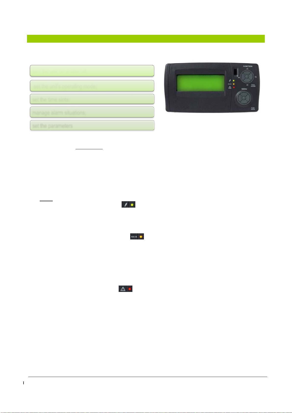
- The purpose of this manual is to provide all the basic information needed to run a UNIT equipped with
EXTK PRO keyboard (see Fig. 1 page 7).
- The recipients of this manual include those involved in the basic operation of the UNIT.
3 USE OF THE DEVICE
Permitted use
This unit is used for the control of the ROOF-TOP unit. For safety reasons, the control device must be installed
and used according to the instructions provided and in particular, under normal conditions, live parts must not
be accessible.
The device must be protected from water and dust according to the application, and should only be accessible
with the use of tools.
Unintended use
Any use other than that expressly permitted is prohibited. Please note that the relay contacts supplied are
functional and are subject to failure, (since they are managed by an electronic component they can short or
remain open). Any protection devices required by product standards or dictated by common sense for obvious
safety reasons should therefore be made outside of the instrument.
4 RESPONSABILITIES AND RESIDUAL RISKS
AERMEC SpA are not liable for any damages arising from:
• installation/use other than that prescribed and, in particular, that does not comply with safety requirements
laid down by regulations and/or specified in the present;
• use on equipment that do not provide adequate protection against electric shock, water and dust following
the assembly;
• use of devices that allow access to hazardous parts without the use of tools;
• installation/use on equipment not conforming to regulations and provisions in force.
5 WEEE DIRECTIVE (FOR EU ONLY)
WEEE Directive (for EU only)
All materials must be recovered or disposed of in accordance with national regulations.
• The WEEE Directive requires that the disposal and recycling of electrical and electronic
equipment must be managed through a special collection, in appropriate centres, separate
from the one adopted for the disposal of mixed municipal waste.
• The user is obliged not to dispose of equipment at the end of its useful life as municipal
waste, but to dispose of it in a special collection centres.
• The units covered by the WEEE Directive are marked with the above symbol.
• Potential effects on the environment and human health are presented in this manual.
• Additional information may be obtained from the manufacturer.

.
User manual RTE
Page 5 of 25 0412-6180480 Rev.00
6 DIAGRAM OF THE PARAMETERS MASKS
ThismenucanbeaccessedwithoutPASSWORD

User manual RTE
Page 6 of 25 0412-6180480 Rev.00
ThismenucanonlybeaccessedwithPASSWORD

User manual RTE
Page 7 of 25 0412-6180480 Rev.00

.
User manual RTE
Page 8 of 25 0412-6180480 Rev.00
7 USER INTERFACE
The Figure 1 illustrates the keyboard for the user interface which allows to perform all operations
concerning the use of the controller and in particular:
The keyboard, with degree of protection IP65, consists of:
- a graphic 4-line LCD display .
When any one of the keys is pressed, the monitor lights up for 10 seconds. In normal view (main view with
default menu) the "menu" is displayed and allows:
to view the inputs and outputs of the XTMH basic card (the card that translates commands
from the control card in machine language)
to enter the password
to access the configuration mode
- 3 leds that indicate:
Green Led 1 (first from the top).
Indicates the presence of the supply voltage.
Lights if the unit is electrically powered (main switch in the ON position) even when off or in stand-
by; it will be off if the device is not powered (main switch set to OFF).
Yellow Led 2 (second from the top).
Indicates that there is communication between the keyboard and the controller.
Lights if there is communication and off if the communication is interrupted or absent.
The absence of communication has a delay time of 10 seconds, after which the yellow LED flashes
and the display will show “Energy XT PRO”.
To restore communication, the yellow LED lights and the lack of communication status previously
displayed appears again on the screen.
Red Led 3 (third from the top).
Indicates that an alarm is present.
Lights if there is at least one alarm active;
Off if there are no alarms active;
Flashing if there are alarms active that can be turned off manually.
Figure1:Keyboardonthemachine(standard)and/or
remotekeyboard(accessory)
turn the unit on and/or off;
set the unit's operating mode;
set the time slots;
manage alarm situations;
set the parameters

User manual RTE
Page 9 of 25 0412-6180480 Rev.00
Function keys: F1, F2, F3, F4 and Push: ON/OFF
These buttons provide access via shortcuts to specific commands that are
present in the general menu. These keys give direct access to some commands
without following the canonical path foreseen by the menu.
The unit is turned on or off by pressing the centre button for a few seconds (PUSH: ON / OFF).
Act on the four external positions (F1: above; F3: below; F2: right; F4: left):
• a single press: accesses the Functions menu
• pressing for a few seconds:
Menu keys: Arrow up, down, right, left and central Enter/Push key.
With a single press of the keys:
In addition to the main keyboard a remote keyboard is also possible (optional), which repeats the main
keyboard functions; to connect the remote keyboard follow the instructions on the wiring diagram of the unit.
The indications for fixing the remote keyboard to a suitable support are included in the packaging of the
accessory itself. The accessory normally comes packed and positioned inside the electrical panel of the unit.
- F1: display of the temperatures detected;
- F2: display of the components' operating condition (e.g. if the
operation is either hot or cold);
- F3: access to the alarms menu;
- F4: access to the time slot menu.
top arrow: scrolls the items in the menu upwards;
bottom arrow: scrolls the items in the menu downwards;
left arrow (ESC): returns to the previous menu (each press
returns by one level)
right arrow: accesses to possible changes and/or confirms the
set value
central Push key: confirms the command or accesses the
indicated menu.
Push ON/OFF
TEMP. 01/03
Room 17.9 °C
Limit 17.6 °C
Outside 3.8 °C
STATUS 01/03
System Hot
Del. fan On
Damper 30%
ALARMS 01/02
Bios Alarms
User Alarms
Probe errors
TIME SLOTS 01/01
Timer No
Timer type Weekly
Settings
UP
DOWN
RIGHT
ENTER/PUSH
ESC

.
User manual RTE
Page 10 of 25 0412-6180480 Rev.00
8 SWITCHING ON AND OFF
The unit is turned on or off by pressing the centre button for a few seconds (PUSH: ON / OFF).
The unit can be turned on or off by pressing the Push: ON/OFF key (centre button of the
Function keys) on the machine control panel or remote control panel (accessory) for a
few seconds.
In the event of power failure during the operation of the machine, when the power returns, the unit starts to
operate again in the same manner prior to the power supply failure.
When the unit turns off the "shut down" procedure starts and stops the machine. "Off" is displayed only after all
components have been switched off.
In the event of power failure during the shut down procedure of the machine, when the power returns the
machine restarts Off (standby).
If the unit has already been activated with the Push:ON/OFF key, it
can be subsequently turned off and on again
- from the dedicated remote digital input
(refer to the wiring diagram for indication of
the remote ON/OFF contact). This contact
can only turn the unit off:the unit cannot be
turned on again by the Push: ON/OFF if the
contact is closed
- by the time slot, if enabled.
- to use the remote contact for the first time, turn the unit on with the Push: ON/OFF key;
- the shut down of the unit via the remote contact is priority both on the shut down by the Push: ON/OFF
key as well as on the time slot;
- if the Push: ON/OFF key has to be used, the remote contact must be ON and/or the time slot disabled.
PUSH: ON/OFF

User manual RTE
Page 11 of 25 0412-6180480 Rev.00
The initial default mask (on two pages/screens).
A mask appears on two pages when the controller is turned on
Each screen can display 4 lines at a time.
The second screen or the subsequent screens can be displayed by
pressing the arrow keys at the bottom of the Menu keys group.
NB: The following screens can be displayed also by
- pressing repeatedly the ESC key on the left of the Menu Keys Group.
Hh:mm NRGXTPRO 01/02
Off No Alarm
Room Temp. 19.8 °C
Set Point
Hh:mm NRGXTPRO 02/02
Time slots
Summer / Winter / Auto
Menu

.
User manual RTE
Page 12 of 25 0412-6180480 Rev.00
9 MODIFYING THE SET-POINT
The temperature settings can be modified as required from the initial
default mask.
Position the cursor on the text "Set Point" using the UP-DOWN keys:
press the ENTER/PUSH key
1 arrow DOWN to select the value to
modify (WINTER - SUMMER);
2 Right arrow to select the value;
3 ENTER/PUSH to modify it (the value
flashes);
4 UP arrow or DOWN arrow to modify it;
5 ENTER/PUSH to confirm. Left
arrow/ESC to end the editing of the
value selected.
6 Left arrow/ESC to return to the initial
screen.
- Modify the summer SETPOINTS by repeating steps 1 to 6.
- To return to the default mask, press the "Left arrow" key several
times.
Hh:mm NRGXTPRO 01/02
Off No Alarm
Room Temp. 19.8 °C
Set Point
SET-POINT 01/01
Winter 20.0 °C
Summer 25.0 °C
SET-POINT 01/01
Set
WINTER
20,0 °C
SET-POINT 01/01
Winter 20.0 °C
Summer 25.0 °C
SET-POINT 01/01
SET
SUMMER
25,0 °C

.
User manual RTE
Page 13 of 25 0412-6180480 Rev.00
10 SELECTION OF THE FUNCTION MODE
The unit can be programmed to produce cool air in the summer and warm air in the winter (only if the
management program of the time slots has not been activated).
In order to be able to modulate the required performance, the
SUMMER/WINTER/AUTO program,
inserted in the main menu at page 02/02
and accessible by scrolling the UP - DOWN
keys on the main menu, is used;
COLD will be used during warm weather to produce cool/cold air;
HOT will be used during colder weather to produce hot air;
Depending on the temperatures set in the SET-POINT, AUTO
automatically manages the operation of the unit
- confirm the program selection by double pressing ENTER/PUSH to make the wording on the display
flash;
- scroll the menu with the UP-DOWN keys to select: COLD, HOT andAUTO; press ENTER/PUSH ("OK" is
displayed for a fraction of a second).
Press ESC twice to return to the start menu
Hh:mm NRGXTPRO 02/02
Time slots
Summer / Winter / Auto
Menu
Mode 01/01
Manual mode
Cold
Mode 01/01
Manual mode
Hot
Mode 01/01
Manual mode
Auto
UP
DOWN
RIGHT
ENTER/PUSH
Esc

.
User manual RTE
Page 14 of 25 0412-6180480 Rev.00
11 TIME SLOTS
Up to 4 different interventions called "slots" can be set for each day of the week. They can be activated
individually and within them all the information necessary to operate the unit in automatic mode can be
entered.
The management of the time slots can be accessed from the main
menu; scroll on the main menu with the DOWN key as far as the
heading TIME SLOTS appears.
After confirming the selection with the centre key of the MENU, the
Timer, Timer type and Settings modes appear on screen.
This menu can be accessed directly by pressing and holding the F4
key.
The TIMER menu is only accessed to set or not the application:
TIMER, ENTER, right key to make the YES/NO flash, UP - DOWN key
to perform the desired variation, confirm with ENTER and exit a level
with ESC + ESC.
TheTIMER TYPE can be selected from the TIMER menu by means
of the UP–DOWN keys;
the following types are available:
1 - 7/7:
in which the data can be
entered subdivided in each
day of the week in order to
meet all user needs;
2 - Weekly:
in which is set a standard
value repeated for each day
of the week;
3 - 5+2:
in which the week is
essentially managed with
working slots and festive
slots.
Hh:mm NRGXTPRO 02/02
Time slots
Summer / Winter / Auto
Menu
TIME SLOTS 01/01
Timer Yes
Timer type Weekly
Settings
TIMER 01/01
TIME SLOTS
No
TIME SLOTS 01/01
Timer No
Timer type Weekly
Settings
TIMER TYPE 01/01
TIME SLOTS
TYPE 7/7
TIMER TYPE 01/01
TIME SLOTS
TYPE Weekly
TIMER TYPE 01/01
TIME SLOTS
TYPE 5+2

User manual RTE
Page 15 of 25 0412-6180480 Rev.00
Depending on the choice made (7/7, Weekly, 5+2) the SETTINGS menu,
of the TIME SLOTS menu, will give you the possibility to set options
according to your personal needs: by the way, in any case 4 slots are
managed for each type of timer, in which it is possible, for each of them, to
change the condition of the unit.
e.g.: Slot 1- on at 7.00 am;
Slot 2- change to the temperature setting at 10.30 am;
Slot 3- change to the temperature setting at 16.30 pm;
Slot 4- off at 20.00 pm.
or
Slot 1- on at 7.30 am;
Slot 2- change to the temperature setting at 10.30 am;
Slot 3- off at 20.00 pm.
Slot 4- not in use.
Etc.
- Timer type 7/7:
- scroll theTime Slots menu with the UP-DOWN keys till you find
SETTINGS, then press ENTER;
- all the days of the week that can be selected via the UP-DOWN keys
appear
; select the desired day by pressing ENTER (e.g.:Monday);
- SLOT1 appears on the screen with the TIME setting, press ENTER
(the time flashes);
- press the UP-DOWN key to select the hours, press ENTER to confirm
(the hours continue to flash), press ESC to exit by one level;
- press the DOWN key, press the ENTER key to select the MINUTES;
- press the UP-DOWN key to select the minutes, press ENTER to
confirm (the minutes continue to flash), press ESC to exit by one level;
- press DOWN and then ENTER to select the MODE that can be:
TIME SLOTS 01/01
Timer No
Timer type Weekly
Settings
TIME SLOTS 01/01
Timer No
Timer type Weekly
Settings
SETTINGS 01/03
Monday
Tuesday
Wednesday
MONDA
Y
01/27
SLOT 1
TIME 8 h
MONDA
Y
02/27
SLOT 1
MINUTES 0m
MONDA
Y
03/27
SLOT 1
MODE Manual Set

User manual RTE
Page 16 of 25 0412-6180480 Rev.00
1- MANUALSET, in this slot the machine is on and takes as standards the
temperatures set in the initial set-point;
2 -MANUALMODE, in this slot the machine is on and takes as standard the
settings (hot or cold mode) set in the initial set-point;
3 -AUTO, in this mode the machine automatically switches from hot mode or
cold mode regardless of the set-point value;
4 -COLD, used in this mode during the hot season, the machine produces
fresh/cold air based on the temperature set in the related slot;
5 -HOT, used in this mode during the cold season, the machine produces hot air
based on the temperature set in the related slot;
6 -OFF, by selecting this mode the machine is off.
Having defined the parameters of the previously listed MANUAL
SETPOINTS, press the ESC button once to return to the previous
menu
DOWN key, ENTER, to select the OPTIONS that can be:
THE "OPTIONS" MENU provides:
1 - Selecting OFF with the ENTER key, the machine is off,
ENTER;
2 - Pressing UP-DOWN finds the NIGHT command; the
NIGHT mode gives an exchange of air with the outside
through the appropriate opening of the dampers and
forced ventilation: however, this happens when the outside
temperature is favourable to meet the setup requirements.
All other regulators are disabled; ENTER;
3 - Pressing the UP-DOWN keys the FAN command
appear, if the mode is activated, the air in the room is
recirculated through the activation of the fan: press
ENTER, press ESC to return to the Slot 1 menu;
MONDA
Y
04/27
SLOT 1
OPTIONS OFF
MONDA
Y
04/27
SLOT 1
OPTIONS Off
MONDA
Y
25/27
SLOT 1
OPTIONS Night
MONDA
Y
25/27
SLOT 1
OPTIONS Fan
Esc DOWN
Enter
RI
UP

User manual RTE
Page 17 of 25 0412-6180480 Rev.00
-Again in theTIME SLOTS 1 menu, with the UP – DOWN’, it is
possible to select the SUMMER SET-POINT (temperature); press
ENTER to select, press the UP - DOWN key to adjust the temperature
depending on your needs, press ENTER to confirm, press ESC to exit
by one level;
-Again in theTIME SLOT 1 menu, with the UP– DOWN key, select the
WINTER SET-POINT (temperature); press ENTER to select, press the
UP - DOWN key to adjust the temperature depending on your needs,
press ENTER to confirm, press ESC to exit by one level;
All of these adjustments must be made for each individual day of
the week.
Timer type WEEKLY: for this type of selection, the software manages each day of the week in the same
way; The settings are defined step-by-step in the previous paragraph 7/7; there are four time slots
for this module also.
Timer type 5+2: for this type of selection, the software manages the week into two sections, the work
section from Monday to Friday and the festive section, from Saturday to Sunday, managing them
individually; there are four time slots for this module also. To enter the time slots, use the same method
proposed for the 7/7
MONDA
Y
05/27
SLOT 1
SUMMER SET 25.0°C
MONDA
Y
06/27
SLOT 1
WINTER SET 21.0°C

.
User manual RTE
Page 18 of 25 0412-6180480 Rev.00
12 ALARMS DIAGNOSTICS
Generally, all types of alarms and probe errors are managed when the machine is on or when the machine is
shutting down. When the status of the system changes from shutting down to off, when exiting the
configuration mode or start-up, the alarms and probe errors are reset (though they remain registered in the
log).
An exception to the previous management:
NB: The alarm management is disabled in configuration mode.
Signal in the event of an alarm and error with Red LED
The presence of alarms and/or probe errors is signalled by the red LED on the keyboard and, if provided, from
the menu. The LED lights in the presence of at least one active alarm, flashing if there are only alarms that
have returned for some reason (not active) and can therefore be reset, off in the other cases. The LED status
is not restricted to the status of the unit (it also works with the unit off). The following paragraphs list the types
of alarms that can be found: for the resolution of all alarms (the presence of which is shown by the red
LED with fixed light) please contact the AERMEC service department.
Cumulative alarm relay
The presence of active alarms with manual reset, probe errors or anti-freeze alarm are signalled by the
cumulative alarm relay inside the electrical panel of the unit. The relay also functions with the system off (of
course for those alarms that are active when the system is off).
12.1 Thermoregulation alarms
- the BIOS alarms that are also managed even when the unit is off (if the system is off, the cumulative
alarm relay does not trip even if the BIOS is active. The red LED of the keyboard lights and “!Hw” appears
on the keyboard)
11.1.1 High temperature alarm
In the event the value of the temperature measured by the control probe is maintained at the higher level
set and theunit is setto produce cool/cold air, the high-temperature alarm is generated; it is a display only
alarm and manual reset.
11.1.2 Low temperature alarm
In the event the value of the temperature measured by the intake probe stays at the lower level than that
set and the unit is set to produce hot air, the low temperature alarm is generated; it is a display only alarm
and manual reset.

User manual RTE
Page 19 of 25 0412-6180480 Rev.00
12.2 Alarm reset
When an alarm/error condition persists on the unit, it is signalled on the
main screen of the display with "Alarm" and the lighting of the red led ,
flashing or fixed.
To know the cause that generated the alarm, simply press and hold the
F3 key (shortcut) of the FUNCTION key;
the screen shows a first part with the Bios Alarms, User Alarms and
Probe Errors and a second part proposes the Alarms reset option, an
alarm log and the cancel option of the alarms log (option that can be
performed by entering the password).
The High and Low temperature alarms are reset:
- Manually if resettable
- When the system is turned on or off;
- When exiting the configuration mode ;
- Press ENTER/PUSH from the MENU to select the “BiosAlarms”; the
display may show “EMPTY” meaning that the alarm signalled is not in
the Bios or it may show the wording of the type of alarm detected.
Press the ESC key and try to see, moving with the UP- DOWN keys, if
an alarm in the User alarms is detected. The same procedure can be
used to check the Probe Errors.
- Having established what type of error has been detected, with the UP
- DOWN keys, select ResetAlarms and press ENTER/PUSH of the
MENU: "OK" is displayed for a fraction of a second and, resetting the
alarm, the alarms screen appears again.
Note that the option "Cancel Log" is active after entering the
password
By pressing the ESC key of the MENU, the system returns to the main
screen; the wording “Alarms” changes into “No alarm” and the red
LED switches off .
Hh:mm NRGXTPRO 01/02
Hot ! Alarms
Room Temp. 19.8 °C
Set Point
ALARMS 01/02
Bios Alarms
User Alarms
Probe errors
EMPTY
ALARMS 02/02
Alarms Reset
Log
Cancel Log
Hh:mm NRGXTPRO 01/02
Hot No Alarm
Room Temp. 19.8 °C
Set Point

User manual RTE
Page 20 of 25 0412-6180480 Rev.00
*TIMEOUT INT. EXP.
*CRC EEPROM BIOS ERROR
*CRC EEPROM USER ERROR
*REAL TIME CLOCK NEED TO BE SET
*REAL TIME CLOCK COMM. ERROR
*REAL TIME CLOCK REGISTERS
*POWER LIMITATION
*LOW ROOM TEMPERATURE
*HIGH ROOM TEMPERATURE
*ANTI-FREEZE
*HIGH PRESS. CIRCUIT 1 PROBE
*HIGH PRESS. CIRCUIT 2 PROBE
*HIGH PRESS. DIGITAL CIRCUIT 1
*HIGH PRESS. DIGITAL CIRCUIT 2
*LOW PRESSURE CIRCUIT 1
*LOW PRESSURE CIRCUIT 2
*THERMAL SWITCH COMPRESSOR 1
*THERMAL SWITCH COMPRESSOR 2
*THERMAL SWITCH COMPRESSOR 3
*THERMAL SWITCH COMPRESSOR 4
*THERMAL SWITCH FAN 1
*THERMAL SWITCH FAN 2
*DEL. FAN THERMAL SWITCH
*FILTERS BLOCKED
*FILTERS DIRTY
*AIR FLOW
*HEATERS THERMAL SWITCH
*THERMAL SWITCH HEAT 1
*THERMAL SWITCH HEAT 2
*THERMAL SWITCH HEAT 3
*THERMAL SWITCH HEAT 4
*DUAL STAGE GEN. THERMAL SWITCH
*SMOKE ^
*PHASE SEQUENCE ^
*MOD. GEN. THERMAL SWITCH
*SYSTEM HOURS OF USE
*MOD.GEN. HOURS OF USE
*ELE. COIL HOURS OF USE
*HOURS OF USE COMPRESSOR 1
*HOURS OF USE COMPRESSOR 2
*HOURS OF USE COMPRESSOR 3
*HOURS OF USE COMPRESSOR 4
*INTAKE TEMP. ^
*DELIVERY TEMP. ^
*EXTERNAL TEMP. - DYNAMIC SET
*ANTI-FREEZE
*DIFF. PRESS. DEL. FAN
*HUMIDITY LIMIT ^
*EXTERNAL HUMIDITY ^
*AMBIENT HUMIDITY ^
*AIR QUALITY ^
*HIGH PRESSURE, CIRCUIT 1
*HIGH PRESSURE, CIRCUIT 2
*LOW PRESSURE CIRCUIT 1
*LOW PRESSURE CIRCUIT 2
*COND. TEMP. CIRCUIT 1 **
*COND. TEMP. CIRCUIT 2 **
12.2.1 BIOS alarms status list
12.2.2 USER alarms status list
12.2.3 Probe error alarms status list
Other manuals for RTE240
1
This manual suits for next models
1
Table of contents
Other AERMEC Control Unit manuals
Popular Control Unit manuals by other brands

IDS
IDS X-Series X-SMS V2 Quick user guide

tams elektronik
tams elektronik HELIOS.DC manual

Pfeiffer Vacuum
Pfeiffer Vacuum EVA 016 H operating manual

TAIYO YUDEN
TAIYO YUDEN EYSMJCS user manual

Allen-Bradley
Allen-Bradley ControlLogix 1756-PLS installation instructions

Panasonic
Panasonic AFP0HC32ET user manual

Inxpect
Inxpect SRE 100 Series manual

Tormatic
Tormatic T 100 DES Assembly and operating instructions

Woodward
Woodward QuickTrip Installation and operation manual

Steren
Steren AT-50 user manual

Fluke
Fluke PM Series instruction sheet

ASCO Valves
ASCO Valves 8210 Series Installation & maintenance instructions