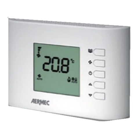
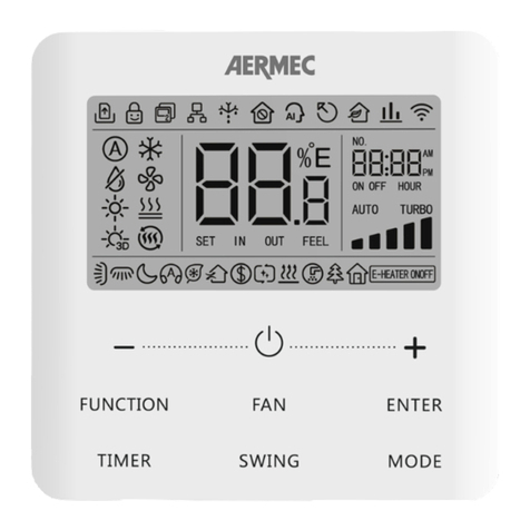
AERMEC WRCB User manual

22/10 – 5330601_01
Translation of Original instructions
www.aermec.com
User manual
WIRED CONTROLLER
WRCB

All specications are subject to change without prior notice. Although every eort has been made to ensure accuracy, Aermec shall not be held liable for any errors or
omissions.
This marking indicates that this product should not be disposed with other household wastes throughout the EU. To prevent possible harm to the envi-
ronment or human health from uncontrolled disposal of Waste Electrical and Electronic Equipment (WEEE), please return the device using appropriate
collection systems, or contact the retailer where the product was purchased. Please contact your local authority for further details. Illegal dumping of
the product by the user entails the application of administrative sanctions provided by law.
Dear customer,Thank you for choosing an Aermec product. It is the fruit of many years of experience and special design studies and has been made of the highest grade
materials and with cutting edge technology.In addition, all our products bear the CE mark indicating that they meet the requirements of the European Machine Direc-
tive regarding safety. The quality level is being constantly monitored, so Aermec products are synonymous with Safety, Quality and Reliability.The data may undergo
modications considered necessary for the improvement of the product, at any time and without the obligation for any notice thereof.
Thank you again.
Aermec S.p.A.

3
TABLE OF CONTENTS
1. User Notice.............................................................................................p.4
2. Wired Controller WRCB ...................................................................p.5
Symbols on LCD......................................................................................p.5
3. Buttons.....................................................................................................p.7
Buttons on the Wired Controller.......................................................p.7
Function of the Buttons .......................................................................p.7
4. Operation Instructions....................................................................p.8
ON/OFF ......................................................................................................p.8
Mode Setting ...........................................................................................p.8
Temperature Setting.............................................................................p.8
Fan Setting................................................................................................p.9
Timer Setting ...........................................................................................p.9
Up & Down Swing Setting ............................................................... p.10
Left & Right Swing Setting (if available)...................................... p.10
Sleep Setting......................................................................................... p.11
Turbo Setting........................................................................................ p.12
Energy Saving Function Setting .................................................... p.13
X-fan Setting ......................................................................................... p.14
Quiet Function Setting...................................................................... p.15
Absent Setting...................................................................................... p.16
I-Demand Setting................................................................................ p.17
WiFi Function Setting......................................................................... p.18
Other Functions................................................................................... p.18
5. Installation and Dismantlement............................................. p.19
Connection of the Signal Line of the Wired Controller.......... p.19
Installation of the Wired Controller .............................................. p.19
Dismantlement of the Wired Controller...................................... p.21
6. Set the indoor unit address (CC2).......................................... p.22
7. Set the indoor unit address (BMS)......................................... p.22
8. Errors Display..................................................................................... p.23

4
USER NOTICE
— Never install the wired controller in the moist circumstance or expose it directly under the sunlight.
— Never beat, throw, and frequently disassemble the wired controller and the wireless remote controller.
— Never operate the wired controller and the wireless remote controller with wet hands.
— Do not remove or install the wired controller by yourself. If there is any question, please contact our after-sales service center.
— The wired controller is a general model, applicable for several kinds of units.Some functions of the wired controller are not available for certain kinds of units, more details
please refer to the owner’s manual of unit. The setting of such unavailable function will not aect unit’s operation.
— The wired controller is universal. The remote receiver is either in the indoor unit or in the wired controller. Please refer to the specic models.
— As for some indoor units connected with the wired controller, if use the remote controller whose set temperature is adjustable under auto mode, the wired controller will
receive the mode signal of remote controller, rather than its set temperature under the auto mode.
— The wired controller is the universal component.When indoor unit has connected with the wired controller, display status of indoor unit is decided by the indoor unit. Valid
status and invalid status are all belong to normal status.
Please read the manual carefully before using and installing this product.

5
WIRED CONTROLLER WRCB
2.1 SYMBOLS ON LCD
2.1.1 Outside View of the Wired Controller
Fig.1: Outside View of the Wired Controller

6
2.1.2 LCD of the Wired Controller
Fig.2: LCD of the Wired Controller
N. Display Function
1 Automatic Indica che è attiva la modalità automatica (in modalità automatica, l’unità interna selezionerà la sua modalità di
funzionamento al variare della temperatura ambiente)
2 Cooling Cooling mode
3 De-Humidication Dry mode
4 Ventilation Fan mode
5 Heating Heating mode
6 Sleep Display when sleep function is set
7 UNAVAILABLE UNAVAILABLE
8 Quiet Display when quiet function is set
9 UNAVAILABLE UNAVAILABLE
10 Absent Display when absent function is set
11 I-DEMAND Display when I-DEMAND function is set
12 WiFi Display when WiFi function is set
13 Child-lock Child-lock status, display when child-lock function is set
14 Up & Down Swing Setting Display when up and down swing function is set
15 UNAVAILABLE UNAVAILABLE
16 Fan speed The fan speed set currently (including auto, low, medium low, medium, medium high, high, and turbo)
17 No card No card in gate control system
18 Left & Right Swing Setting Display when left and right swing function is s
19 X-fan Display when X-fan function is set
20 Temperature It will display the setting temperature
21 UNAVAILABLE UNAVAILABLE
22 Memory Memory status (After power failure and re-energizing the unit, it will resume to ON/OFF status of unit before the power
failure)
23 UNAVAILABLE UNAVAILABLE
24 Save Display when energy-saving function is set
25 Defrost Defrosting status
26 Timer Display when timer status is set
27 Shield Shielding status

7
3 BUTTONS
3.1 BUTTONS ON THE WIRED CONTROLLER
Fig. 3: Buttons on the Wired Controller
21 3 4
5678
3.2 FUNCTION OF THE BUTTONS
N° Name Function
1 SWING/ENTER 1. Function selection and cancellation.
2. Setting of the up and down swing function.
31. Running temperature setting of the indoor unit, range:16~30°C(61~86°F).
2. Timer setting, range:0.5-24 hr.
7
6 FAN Setting of the auto/low/medium low/medium/medium high/ high fan speed.
4 MODE Setting of the Cooling/Heating/Fan/Dry/Auto mode of the indoor unit.
5 FUNCTION Switchover among the functions (Turbo / WiFi / X-FAN etc..)
2 TIMER Timer setting.
8 ON/OFF Turn on/o the indoor unit.
3+4 + MODE
Press them for 5s under o state of the unit to Enter/Cancel the Memory function (If memory is set, indoor unit after power failure and then
power recovery will resume the original setting state. If not, the indoor unit is defaulted to be o after power recovery. Memory o is default
before delivery.).
6+7 FAN + By pressing them at the same time under o state of the unit, will be displayed on the wired controller for the cooling only unit, while
will be displayed on the wired controller for the cooling and heating unit.
3+7 + Upon startup of the unit without malfunction or under o state of the unit,press them at the same time for 5s to enter the lock state, in which
case, any other buttons won’t respond the press. Repress them for 5s to quit this state.
4+7 MODE + Under OFF state, the Celsius and Fahrenheit scales can be switched by pressing "MODE" and "“ " for 5s.
2+5 TIMER + FUNCTION
Under OFF state, it is available to go to the commissioning status by pressing "FUNCTION" and "TIMER" for ve seconds, and let "00" displayed on
the temperature display area by pressing“MODE”, then adjust the options which is shown on the timer area by pressing “ ” and “ ”. There are
totally four options, as follows:
1. Indoor ambient temperature is sensed by the return air temperature sensor (01 displayed on the timer area).
2. Indoor ambient temperature is sensed by the wired controller (02 displayed on the timer area).
3. The return air temperature sensor is selected under the cooling, dry, or fan mode; while the wired controller temperature sensor is selected
under the heating or auto mode. (03 is displayed on the timer area).
4. The wired controller temperature sensor is selected under the cooling, dry, or fan mode; while the return air temperature sensor is selected
under the heating mode. (04 is displayed on the timer display area).
5+6 FUNCTION + FAN Reset the WiFi function: Under o status, press “FUNCTION” +“FAN”combination buttons on its wired controller for 5s. Once“oC” is displayed, this
indicates that reset was successful.
8
4 OPERATION INSTRUCTIONS
4.1 ON/OFF
Press ON/OFF to turn on the unit and turn it o by another press.
Note: The state shown in Fig.4 indicates the “OFF” state of the unit after power o. The state shown in Fig.5 indicates the “ON” state of the unit after power on.
Wi
Fi
Wi
Fi
Fig. 4 “OFF” State Fig. 5 “ON” State
4.2 MODE SETTING
Under the “ON” state of the unit, press MODE to switch the operation modes as the following sequence:
AUTOAUTO COOLING DRY FAN HEATING
4.3 TEMPERATURE SETTING
Press or to increase/decrease the preset temperature. If press either of them continuously, the temperature will be increased or decreased by 1°C (1°F) every 0.5s, as
shown in Fig.6.
In the Cooling, Dry, Fan or Heating mode, the temperature setting range is 16°C~30°C(61°F~86°F).
In the Auto mode, the setting temperature is unadjustable.
Note: If the wired controller receives the signals of remote controller, the wired controller can analyze the set temperature adjustment function of automatic mode of the remote
controller, but it needs to be used with an indoor unit with the set temperature adjustment function of automatic mode.
Fig. 6
Wi
Fi

9
4.4 FAN SETTING
Under the “ON” State of the unit, press Fan and then fan speed of the indoor unit will change circularly as shown in Fig.7.
Fig. 7
Wi
Fi
Auto
(Low) (Medium Low) (Medium) (Medium-High) (High)
4.5 TIMER SETTING
Under the “ON”/”OFF”state of the unit, press Timer to set timer o/on.
Timer on setting: press Timer, and then LCD will display“xx.x hour”, with “hour” blinking. In this case, press “ “ or “ “ to adjust the timing value. Then press SWING/ENTER
to conrm the setting.
Timer o setting: press Timer, if LCD won’t display xx.x hour, and then it means the timer setting is canceled.
Timer o setting under the“ON” state of the unit is shown as Fig.8.
Fig. 8: Timer o Setting under the “ON”State of the Unit
Wi
Fi
Wi
Fi
Wi
Fi
Wi
Fi
Wi
Fi
Turn on the unit, without setting timer Press“TIMER” button to set Press or button to adjust time
Press“SWING/ENTER” to nish timer setting
Press“TIMER” button to cancel
timer setting
Timer range: 0.5-24hr. Every press of or will make the set time increased or decreased by 0.5hr. If either of them is pressed continuously, the set time will increase/
decrease by 0.5hr every 0.5s.

10
4.6 UP & DOWN SWING SETTING
There are two ways for up and down swing mode: simple swing and xed swing. Under o status, press“SWING/ENTER” button and“ ” button simultaneously for 5 seconds,
then switch for simple swing and xed swing is done.
When it is set to be simple swing, under on status, press“SWING/ENTER” button, the mode is activated, press the button again the mode is turned o.
When it is set to be xed swing, press“SWING/ENTER”button, the unit will circularly switch the swing mode according to the order shown below:
4.7 LEFT & RIGHT SWING SETTING (IF AVAILABLE)
Swing On: Press FUNCTION under on state of the unit to activate the swing function. In this case, will blink. After that, press SWING/ENTER to make a conrmation.
After that, press SWING/ENTER to make a conrmation
Swing O: When the Swing function is on, press FUNCTION to enter the Swing setting interface with blinking.
After that, press SWING/ENTER to cancel this function
Swing setting is shown as Fig.9.
Fig. 9: Swing Setting
Wi
Fi
Wi
Fi
Wi
Fi
Wi
Fi
Wi
Fi
11
Turn on the unit, without turning on swing
function
Press“FUNCTION” button into swing state Press“SWING/ENTER” button to conrm
Press“FUNCTION” button into swing statePress“SWING/ENTER” button to cancel
swing
Note:
1. Sleep, Turbo or X-FAN setting is the same as the Swing setting
2. After the setting has been done, it has to press the key “SWING/ENTER”to back to the setting status or quit automatically ve second later.

11
4.8 SLEEP SETTING
Sleep on: Press FUNCTION under on state of the unit till the unit enters the Sleep setting interface.
Press SWING/ENTER to conrm the setting.
Sleep o: When the Sleep function is activated, press FUNCTION to enter the Sleep setting interface. After that, press SWING/ENTER to can this function.
Sleep setting is shown as Fig.10.
Fig. 10: Sleep Setting
Wi
Fi
Wi
Fi
Wi
Fi
Wi
Fi
Wi
Fi
Turn on the unit, without turning on sleep Press“SWING/ENTER” button to
turn on sleep
Press“FUNCTION”button into sleep
Press“SWING/ENTER” button to cancel
sleep

12
4.9 TURBO SETTING
Turbo function: The unit at the high fan speed can realize quick cooling or heating so that the room temperature can quickly approach the setting value.
In the Cooling or Heating mode, press FUNCTION till the unit enters the Turbo setting interface and then press SWING/ENTER to conrm the setting.
When the Turbo function is activated, press FUNCTION to enter the Turbo setting interface and then press SWING/ENTER to cancel this function.
Turbo function setting is as shown in Fig.11.
Fig.11: Turbo Setting
Wi
Fi
Wi
Fi
Wi
Fi
Wi
Fi
Wi
Fi
Turn on the unit, without turning on turbo Press“FUNCTION” button into turbo state Press“SWING/ENTER” to turn on turbo
function
Press“FUNCTION” button into turbo state
Press“SWING/ENTER” to turn o
turbo function

13
4.10 ENERGY SAVING FUNCTION SETTING
Turn on energy saving function:
1. Energy Saving Setting for Cooling
When the unit runs under the COOL or DRY mode, press FUNCTION button to select "SAVE" function option, with "SAVE" ashing, and then press or to adjust the lower
limit, after that, press the SWING/ENTER button to activate this function.
2. Energy Saving Setting for Heating
When the unit runs under the HEAT mode, press FUNCTION button to select "SAVE" function option, with "SAVE" ashing, and then press or to adjust the upper limit,
after that, press SWING/ENTER button to activate this function.
Note: under energy saving setting mode, press “MODE” button to switch the energy saving setting for COOL or HEAT mode.
Cancel energy saving function:
If energy saving function has been set, press FUNCTION button on the panel to select“SAVE”. When "SAVE" icon ashes, if you press SWING/ENTER button without pressing
or button, energy saving function will be canceled; if you press SWING/ENTER button after pressing or button, energy saving function will be activated.
Fig. 12: Energy Saving Function Setting
Wi
Fi
Wi
Fi
Wi
Fi
Wi
Fi
Wi
Fi
Wi
Fi
Turn on the unit with the “SAVE” function
deactivated
Press“FUNCTION”button to select the
“SAVE” function option Press or to adjust the lower
limit
Press“MODE” button to switch to the
“SAVE” setting for heating
Press“SWING/ENTER” button to activate
the “SAVE” function Press or to adjust the upper
limit

14
4.11 X-FAN SETTING
X-FAN function: After the unit is turned o, the water in evaporator of indoor unit will be automatically evaporated to avoid mildew.
In the Cooling or Dry mode, press FUNCTION till the unit enters the X-fan setting interface (X-FAN) and then press SWING/ENTER to active this function.
When the X-FAN function is activated, press FUNCTION to the X-fan setting interface and then press SWING/ENTER to cancel this function.
X-FAN function setting is as shown in Fig.13
Fig.13: X-fan Setting
Wi
Fi
Wi
Fi
Wi
Fi
Wi
Fi
Wi
Fi
Turn on the unit, without turning on X-fan
function
Press“FUNCTION” button into X-fan state Press “SWING/ENTER” button to turn
on X-fan function
Press“FUNCTION” button into X-fan state
Press“SWING/ENTER” button to turn
o X-fan function
Note:
1. When the X-FAN function is activated, if turning o the unit by pressing ON/OFF or by the remote controller, the indoor fan will run at the low fan speed for 2 min, with
“X-FAN” displayed on the LCD. While, if the X-FAN function is deactivated, the indoor fan will be turned o directly.
2. X-FAN function is unavailable in the Fan or Heating mode.

15
4.12 QUIET FUNCTION SETTING
This function is available only for MPG_C, MPG_CS and MPG_DH.
Turn on quiet function:
Under unit on status, press FUNCTION button on the panel to select “Quiet” function option. When “Quiet” or “Auto quiet”ashes, it enters quiet function setting mode. Press
or button to switch between “Quiet” and “Auto quiet” function. Then press SWING/ENTER button to activate this function.
Cancel quiet function:
If quiet function has been set, press FUNCTION button on the panel to select “Quiet” function option.
When“Quiet”or “Auto quiet”ashes, if you press SWING/ENTER button without pressing or button, quiet function will be canceled; if you press SWING/ENTER button
after pressing or button, quiet function will be activated.
Fig. 14: Setting of Quiet Function
Wi
Fi
Wi
Fi
Wi
Fi
Wi
Fi
Wi
Fi
Wi
Fi
Turn on the unit with the “Quiet”function
deactivated
Press“FUNCTION” button to select the
“Quiet” function option
Press or to select the desired type,
“QUIET” or “AUTO QUIET”.
Press“SWING/ENTER” button to activate
this function
Press the Function button to select the
“Quiet” function option
Press“SWING/ENTER” button to deactivate
this function

16
4.13 ABSENT SETTING
Absent on: Press FUNCTION under on state of the unit till the unit enters the Absent setting interface. Press SWING/ENTER to conrm the setting.
Absent o: When the Absent function is activated, press FUNCTION to enter the Absent setting interface. After that, press SWING/ENTER to cancel this function.
Note:
1. This function is only available in heating mode.
2. When this function has been set, set temperature is displayed in 8°C(46°F). In this case, temperature setting and fan speed setting are shielded.
3. This function will be cancelled when switching modes.
4. This function and sleep function cannot be on simultaneously. If Absent function is set rstly and then sleep/quiet function is set, Absent function will be cancelled while
sleep function will be valid, and vice versa.
Fig. 15: Absent Setting
Wi
Fi
Wi
Fi
Wi
Fi
Wi
Fi
Wi
Fi
Turn on the unit,without turning on absent
function
Press“FUNCTION” button into absent state Press“SWING/ENTER” button to turn
on absent function
Press“FUNCTION” button into absent state
Press“SWING/ENTER” button to turn o
absent function

17
4.14 I-DEMAND SETTING
I-Demand function: under this function the indoor air setting temperature in cooling mode is xed at 27°C.
I-Demand on: Press FUNCTION under on state of the unit till the unit enters the I-Demand setting interface. Press SWING/ENTER to conrm the setting.
I-Demand o: When the I-Demand function is activated, press FUNCTION to enter the I-Demand setting interface. After that, press SWING/ENTER to cancel this function.
Note:
1. This function is only available in cooling mode.
2. When this function has been set, set temperature is displayed in SE. In this case, temperature setting and fan speed setting are shielded.
3. This function will be cancelled when switching modes.
4. This function and sleep function cannot be on simultaneously. If I-demand function is set rstly and then sleep/quiet function is set, I-demand function will be cancelled
while sleep function will be valid, and vice versa.
Fig. 16: I-Demand Setting
Wi
Fi
Wi
Fi
Wi
Fi
Wi
Fi
Wi
Fi
Turn on the unit,without turning on
I-demand function
Press “FUNCTION” button into
I-demand state
Press“SWING/ENTER” button to turn
on I-demand function
Press“FUNCTION” button into I-demand
state
Press“SWING/ENTER” button to turn
o I-demand function

18
4.15 WIFI FUNCTION SETTING
It is possible to connect remotely to the system using this function and the EWPE Smart App for iOS and Android devices (available free on Apple Store and Google Play).
EWPE Smart App can only set some common functions of WiFi wired controller: ON/OFF, mode, set temperature, FAN speed, etc.
When using the EWPE Smart App for the rst time, please reset the WiFi function of wired controller (reset WiFi to ex-factory setting): Under o status, press “FUNCTION” +
“FAN” combination buttons on its wired controller for 5s. Once “oC” is displayed,this indicates that reset was successful.
If there is a communication failure for WiFi, after resetting WiFi, the temperature display area of wired controller displays “JF” for 5 seconds, which indicates that the current
reset is invalid.
Press FUNCTION under on state of the unit till the unit enters the WiFi setting interface, the temperature area will display the WiFi status.
Press “ ” or “ ” button to turn on WiFi(“ON”is displayed) or turn o WiFi (“OFF” is displayed), and then press “SWING/ENTER”button to conrm it.
Note:
WiFi can be only be reset or turned o by the buttons on the wired controller rather than the remote controller.
WiFi networking performance is related to the distance between the wired controller and the router and the obstacles between them. During the installation process, the
distance between the wired controller and the router should be as close as possible, and the obstacles should be as little as possible.
If the WiFi signal is not good, use the WiFi signal enhanced router.
The specic situation depends on the actual installation.
4.16 OTHER FUNCTIONS
1. LOCK
Upon startup of the unit without malfunction or under the“OFF”state of the unit, press“ ”and “ ”at the same time for 5s till the wired controller enters the Lock function.
In this case, LCD displays . After that, repress these two buttons at the same time for 5s to quit this function.
Under the Lock state, any other button press won’t get any response.
2. MEMORY
Memory switchover: Under the “OFF”state of the unit, press Mode and“ ”at the same time for 5s to switch memory states between memory on and memory o. When this
function is activated, Memory will be displayed. If this function is not set, the unit will be under the “OFF”state after power failure and then power recovery.
Memory recovery: If this function has been set for the wired controller, the wired controller after power failure will resume its original running state upon power recovery.
Memory contents: ON/OFF, Mode, set temperature, set fan speed and Lock function.
3. SELECTION OF THE TEMPERATURE SENSOR
Under OFF state of the unit, press both“FUNCTION”and“TIMER” for ve seconds to go the commissioning status. Under this status, adjust the display in the temperature dis-
play area to“00” through the button “MODE”, and then adjust the option of the temperature sensor in the timer display area through the button “ ” or " ".
1. Indoor ambient temperature is sensed at the return air inlet (01 in the timer display area).
2. Indoor ambient temperature is the sensed at the wired controller (02 in the timer display area).
3. Select the temperature sensor at the return air inlet under the cooling, dry and fan modes, while select the temperature sensor at the wired controller under the heating
and auto modes. (03 in the timer display area).
4. Select the temperature sensor at the wired controller under the cooling, dry and fan modes, and select the temperature sensor at the return air inlet under the heating
mode and auto modes (04 displayed in the timer display area).
After the setting, press "SWING/ENTER" to make a conrmation and quit this setting status.
Pressing the button“ON/OFF”also can quit this commissioning status but the set data won’t be memorized.
Under the commissioning status, if there is no any operation in 20 seconds after the last button press, it will back to the previous state without memorizing the current data.
Note: set, the wired controller will select the ambient temperature sensor according to the model of connected IDU; if it connects to cassette type IDU, duct type IDU, oor ceiling
type IDU, ceiling type IDU, it will adopt 3, otherwise it will adopt 1. If the type of ambient temperature sensor is set manually, the wired controller will subject to the manual setting,
and will not set according to automatic IDU model selection.
4. SELECTION OF THE FAN SPEED
Under OFF state of the unit, press both the buttons "FUNCTION" and "TIMER" for ve seconds to go to the commissioning status, and then adjust the display in the temperature
display area to 01 through the button “MODE”and adjust the setting of the fan speed, which comes to two options:
— 01: Three low fan speeds;
— 02: Three high fan speeds.
After the setting, press "SWING/ENTER" to make a conrmation and quit this setting status.
Pressing the button“ON/OFF”also can quit this commissioning status but the set data won’t be memorized.
Under the commissioning status, if there is no any operation in 20 seconds after the last button press, it will back to the previous state without memorizing the current data.

19
5 INSTALLATION AND DISMANTLEMENT
5.1 CONNECTION OF THE SIGNAL LINE OF THE WIRED CONTROLLER
— Open the cover of the electric control box of the indoor unit.
— Let the single line of the wired controller through the soleplate of wired controller.
— Connect the signal line of the wired controller to the 4-pin socket of the indoor unit.
— The communication distance between the main board and the wired controller can be up to 20 meters (the standard distance is 8 meters)
5.2 INSTALLATION OF THE WIRED CONTROLLER
Fig. 17: Accessories for the Installation of the Wired Controller
1 3 42
PVC
N° 1 2 3 4
Name Wired Controller Screw M4X25 Soleplate of the Wired Controller Socket box embedded in the wall
Fig. 18
3 5
12
4
Note: In the back side of the Wired Controller, it is possible to nd:
— CN1, which is RS485 communication interface and is used for connecting the panel to the unit using a 4-core communication wire;
— CN2 and CN3, which are used for connecting the CC2 Accessory if desired.
There is no sequence for these two needle stands. You can connect one or two needle stand(s) basing on the requirement.
Fig. 18 shows the installation steps of the wired controller, please pay attention to the following notes:
1. Prior to the installation, please rstly cut o the power supply of the wire buried in the installation hole, that is, no operation is allowed with electricity during the whole
installation.
2. Pull out the four-core twisted pair line from the installation holes and then let it go through the rectangular hole behind the soleplate of the wired controller.
3. Stick the soleplate of wired controller on the wall and then use screw M4×25 to x soleplate and installation hole on wall together
4. Insert the four-core twisted pair line into the slot of the wired controller.
5. Buckle the front panel and the soleplate of the wired controller together.
For matching with dierent models, the patch cord and the connection wire are provided in the packaging box of wired controller. As shown in g. 19.

20
Fig. 19: Schematic diagram of patch cord and connection wire
Fig. 20: Schematic diagram of connection wire:
Connect terminal 1 with wired controller CN1;
Connect terminal 2 with the terminal 4 of patch cord.
Use the connection wire and patch cord in the packing box of wired controller. Pull out the protection terminal of patch cord at rst, connect the connection wire with the
patch cord according to g. 21, and then insert the terminal 1 of connection wire into the needle stand CN1 of wired controller and insert the terminal 5 of patch cord into the
terminal of wired controller of air conditioner as well.
Fig. 21: Schematic diagram after the connection wire and the patch cord have been connected: connect the terminal 2 of connection wire and the terminal 4 of patch cord
WRCB Control Panel can be connected to the CC2 Accessor.
Fig. 22
WRCB
n.1
WRCB
n.2
WRCB
n.3
CC2
B2 A2 B3 A3 F1 F2 G1 G2
WRCB
n.36
Termination Resistance
CN3 - CN2 - CN1 Terminals
Twisted cable
KEY:
Connection can be made
with the aid of the IC-2P accessory
Indoor
unit
Indoor
unit
Indoor
unit
Indoor
unit
NOTE:
— The twisted cable connecting the centraliser to the wired control panel network (not supplied) must be connected via the IC-2P accessory (mandatory accessory not sup-
plied). The length will vary according to the connected multisplit indoor units.
— The sequence in which the indoor units are connected does not matter, except for the last panel (only use CN2 or CN3 and connect nothing else).
Table of contents
Other AERMEC Controllers manuals

AERMEC
AERMEC HMI-1 User manual

AERMEC
AERMEC NXW Parts list manual

AERMEC
AERMEC WRC50 User manual

AERMEC
AERMEC EXTK PRO User manual

AERMEC
AERMEC HMI-BHP User manual

AERMEC
AERMEC CC2 Guide

AERMEC
AERMEC anz Parts list manual

AERMEC
AERMEC Multichiller-Evo User manual

AERMEC
AERMEC WMT21 User manual

AERMEC
AERMEC pCO3 User manual
Popular Controllers manuals by other brands

Gardner Denver
Gardner Denver GD Connect 12 manual

ICP DAS USA
ICP DAS USA ISaGRAF mPAC Series Getting started

HighPoint
HighPoint RocketRAID mini SAS 3G HBA Series installation guide

Milltronics
Milltronics EnviroRanger ERS500 instruction manual

Superior Electric
Superior Electric 9T92PVC2 Series instructions

Victron energy
Victron energy SmartShunt IP65 Quick installation guide