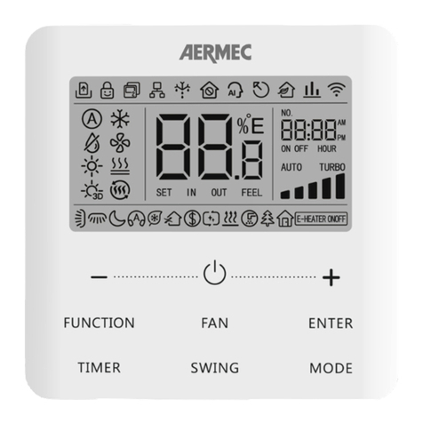
AERMEC WMT21 User manual

FAN COIL CONTROLLER WITH DISPLAY AND 0..10V OUTPUT
THERMOSTAT MIT BILDSCHIRM FÜR FAN-COIL MIT AUSGANG FÜR VENTILATOR 0 .. 10V
THERMOSTAT AVEC ECRAN POUR VENTILO-CONVECTEURS ET SORTIE VENTILATEUR 0 .. 10V
TERMOSTATO CON DISPLAY PARA FAN COIL CON SALIDA VENTILADOR 0 .. 10V
c
WMT21
1412
WMT21
5135600_02
TERMOSTATO A DISPLAY PER FAN COIL CON
USCITA VENTILATORE 0 .. 10V

2

3
DICHIARAZIONE DI CONFORMITÁ / CONFORMITY
DECLARATION / CERTIFICAT DE CONFORMITÉ /
KONFORMITÄTSERKLÄRUNG / DECLARACIÓN DE CONFORMIDAD
Noi, rmatari della presente, dichiariamo soo la nostra esclusiva responsabilità che
l’insieme in oggeo così denito:
We the undersigned declare, under our own exclusive responsibility, that the product:
Nous soussignés déclarons sous notre exclusive responsabilité que le produit:
Wir, die hier Unterzeichnenden, erklären auf unsere ausschließlich Verantwor-
tung, dass das Produkt:
Los que suscriben la presente declaran bajo la propia y exclusiva responsabilidad
que el conjunto en objeto, denido como sigue:
Tipo :
ACCESSORIO - TERMOSTATO DIGITALE PER FANCOIL
Type :
ACCESSORY - DIGITAL THERMOSTAT FOR FANCOIL
Type :
ACCESSOIRE - THERMOSTAT NUMÉRIQUE POUR VENTILO-CONVECTEURS
Typ :
ZUBEHÖR - DIGITAL-THERMOSTAT FÜR GEBLÄSEKONVEKTOR
Tipo :
ACCESORIOS - TERMOSTATO DIGITAL PARA FANCOIL
Modello / Model / Modèle / Model / Modelo : WMT21
Al quale questa dichiarazione si riferisce è conforme alle seguenti norme armonizzate:
To which this declaraon refers, complies with the following standardised regulaons:
Auquel cee déclaraon fait référence, est conforme aux normes harmonisées suivantes:
Auf das sich diese Erklärung bezieht, den folgenden harmonisierten Normen entspricht:
Al que esta declaración se reere, está en conformidad a las siguientes normas armonizadas:
CEI EN 60730-1
CEI EN 60730-2-9
Soddisfacendo così i requisiti essenziali delle seguenti direttive:
Thus meeng the essenal requisites of the following direcves:
Sasfaisant ainsi aux condions essenelles des direcves suivantes:
Womit die grundlegenden Anforderungen folgender Richtlinien erfüllt werden:
Al que esta declaración se refiere, está en conformidad a las siguientes normas armonizadas:
LVD 2006/95/CE
Direttiva Bassa Tensione / Low Voltage Directive / Directive Basse Tension
/
Niederspannungsrichtlinie / Directiva de Baja de Tensión
EMC 2004/108/CE
Direttiva Compatibilità Elettromagnetica / Electromagnec Compability
Direcve / Directive compatibilité électromagnétique / Richtlinie zur elekt-
romagneschen Verträglichkeit / Direcva Compabilidad Electromagnéc
Bevilacqua 29/04/2014
AERMEC S.p.A.
37040 Bevilacqua (VR) Italy–Via Roma, 996
Tel. (+39) 0442 633111
Telefax 0442 93730–(+39) 0442 93566
www.aermec.com - info@aermec.com
WMT21
La Direzione Commerciale – Sales and Marketing Director
Luigi Zucchi
4

5
INSTALLAZIONE - INSTALLATION - AUFSTELLUNG - INSTALLATION - INSTALLACIÓN
Fig. 1 - Abb. 1
2
1
1
Fig. 2 - Abb. 2
2
Fig. 3 - Abb. 3
3

6
Fig. 5 - Abb. 5
Fig. 4 - Abb. 4
4
5
2
1

7
6SELEZIONE JUMPER - JUMPER SET-UP - JUMPER EINSTELLUNG - SÉLECTION JUMPER - SELECCIÓN JUMPER
Frequenza 60Hz - 60Hz frequency - Netzfrequenz 60Hz
- Fréquence 60Hz - Frecuencia 60Hz
JP3
JP4
JP1
JP2
Alimetazione 230V~ (impostazione di fabbrica)
230V~ power supply (factory setting)
Betriebsspannung 230V~ (Werkseinstellung)
Alimentation 230V~ (conguration d’usine)
Alimentación 230V~ (ajustado de fábrica)
JP1
JP2
Alimetazione 24V~ - 24V~ power supply -
Betriebsspannung 24V~ - Alimentation 24V~-
Alimentación 24V~
JP3
JP4
Frequenza 50Hz (impostazione di fabbrica)
50Hz frequency (factory setting)
Netzfrequenz 50Hz (Werkseinstellung)
Fréquence 50Hz (conguration d’usine)
Frecuencia 50Hz (ajustado de fábrica)
JP5
Congurazione parametri abilitata
Parameter conguration enabled
Zugang zur Parameterebene freigegeben
Conguration paramètres autorisée
Conguración parámetros habilitada
JP5
Congurazione parametri disabilitata
Parameter conguration disabled
Zugang zur Parameterebene gesperrt
Conguration paramètres non autorisée
Conguración parámetros deshabilitada
Fig. 6 - Abb. 6

8
ESEGUIRE ICOLLEGAMENTI ELETTRICISEGUENDO LO SCHEMA
DI COLLEGAMENTO PIU’ APPROPRIATO (FIG. 8, 9, 10, 11) E LE
POSSIBILI VARIANTI (FIG. 12, 13); LEGGERE ATTENTAMENTE
IL PARAGRAFO “COLLEGAMENTI ELETTRICI“.
PERFORM THE ELECTRICAL CONNECTIONS FOLLOWING THE
MOST APPROPRIATE CONNECTION DIAGRAM (FIG. 8, 9, 10,
11) AND THE POSSIBLE VARIANTS (FIG. 12, 13). CAREFULLY
READ THE “ELECTRICAL CONNECTIONS“ PARAGRAPH.
ELEKTRISCHER ANSCHLUSS - VERWENDEN SIE DIE
NACHFOLGENDEN VARIANTEN (ABB. 8, 9, 10, 11) ODER DIE
ALTERNATIVEN VARIANTEN (ABB. 12, 13). BEACHTEN SIE
DEN ABSCHNITT “ELEKTRISCHE ANSCHLÜSSE”.
EXÉCUTER LES CONNECTIONS ÉLECTRIQUES SUIVANT
LE SCHÉMA DE CONNECTION LE PLUS APPROPRIÉ (FIG.
8, 9, 10, 11) ET LES POSSIBLES VARIANTES (FIG. 12, 13);
LIRE ATTENTIVEMENT LE PARAGRAPHE “CONNECTIONS
ÉLECTRIQUES“.
REALIZAR LAS CONEXIONES ELÉCTRICAS SIGUIENDO EL
ESQUEMA DE CONEXIÓN MÁS APROPIADO (FIG. 8, 9, 10, 11) Y
LAS POSIBLES VARIANTES (FIG. 12, 13); LEER ATENTAMENTE
EL PÁRRAFO “CONEXIONES ELÉCTRICAS“.
7 8
1
1
23Fig. 7 - Abb. 7

9
LEGENDA - EXPLANATION - ERLÄUTERUNG - LÉGENDE - REFERENCIA
JP2: Selezione alimentazione a 24V~ - 24V~ selection - Auswahl Anspeisung zu 24V~ - Sélection alimentation à 24V~ - Selección alimentación a 24V~
V HEAT: Uscita segnale 0..10V caldo - 0..10V heating signal output - Ausgang Heizen, 0..10V - Sortie signal 0..10V chaud - Salida señal 0..10V calor
V COOL: Uscita segnale 0..10V freddo - 0..10V cooling signal output - Ausgang Kühlen 0..10V - Sortie signal 0..10V froid - Salida señal 0..10V frío
V FAN: Uscita segnale 0..10V ventilatore - 0..10V fan signal output - Signalausgang 0..10V Ventilator - Sortie signal 0..10V ventilateur - Salida señal 0..10V ventilador
HEAT: Uscita valvola caldo - Heating valve output - Ausgang Heizventil - Sortie vanne chaud - Salida válvula calor
COOL: Uscita valvola freddo - Cooling valve output - Ausgang Kühlventil - Sortie vanne froid - Salida válvula frío
E/I: Ingresso remoto per l’attivazione della funzione ‘Estate/Inverno centralizzata’(1)
Remote input to activate ‘centralised Summer/Winter’ function(1)
Eingang zur zentralen Umschaltung zwischen ‘Sommer/Winter’(1)
Entrée à distance pour l’activation de la fonction `Été/Hiver centralisée’(1)
Ingreso remoto para activación de la función “Verano/Invierno centralizada”(1)
RDC: Ingresso remoto per l’attivazione della funzione ‘Economy‘(1)
Remote input to activate ‘Economy’ function(1)
Eingang zur Aktivierung ’ECO-Betrieb‘(1)
Entrée à distance pour l’activation de la fonction ‘Economy‘(1)
Ingreso remoto para la activación de la función ‘Economy’(1)
M: Motore ventilatore a 3 velocità - 3 speed fan motor - 3-stuger Ventilator - Moteur ventilateur à 3 vitesses - Motor ventilador a 3 velocidad
ECM: Motore elettronico - Electronically commutated motor - EC-Motor - Moteur électronique - Motor ventilador
Sc: Servocomando 0..10V - 0..10V Floating actuator - 0..10V Ansteuerung - Servocommande 0..10V - Servomando 0..10V
SW: Sonda acqua di mandata - Supply water sensor - Wasserzulaufsonde - Sonde eau de refoulement - Sonda agua de envío
SA: Sonda ambiente - Room sensor - Raumtemperaturfühler - Sonde ambiance - Sonda ambiente
SCHEMA DI COLLEGAMENTO - WIRING DIAGRAM - SCHALTSCHEMA - SCHÉMA DE BRANCHEMENT - ESQUEMA DE CONEXIÓN

10
ATTENZIONE! La funzione associata al terminale 8 può essere modicata nel parametro C23.
WARNING! The C23 parameter of the function associated to the terminal 8 can be changed.
ACHTUNG! Der Parameter C23, gekoppelt mit der Klemme 8, kann modiziert werden (Ausgang).
ATTENTION! La fonction associée au terminal 8 peut être modiée avec le paramètre C23.
ATENCIÓN! La función asociada al terminal 8 puede ser modicada en el parámetro C23.
Note - Notes - Hinweis - Remarques - Note:
(1): La funzione associata all’ingresso può essere modicata nei parametri C17, C18 e C19.
The C17, C18 and C19. parameters of the function associated to the input can be changed.
Die Parameter der Eingänge können individuell eingestellt werden, siehe C17, C18 und C19.
La fonction associée à l’entrée peut être modiée dans les paramètres C17, C18 et C19.
La función asociada al ingreso puede modicarse en los parámetros C17, C18 y C19.
CF: Ingresso remoto per l’attivazione della funzione ‘Contatto nestra‘(1)
Remote input to activate ‘Window contact’ function(1)
Eingang zur Aktivierung Funktion ‘Fensterkontakt‘(1)
Entrée à distance pour l’activation de la fonction ‘Contact fenêtre‘(1)
Ingreso remoto para la activación de la función ‘Contacto ventana’(1)
RS: Connettore per il collegamento della sonda temperatura ambiente remota, vedere paragrafo “Collegamenti elettrici“
Connector for remote room temperature sensor connection. See “Electric connections“
Anschluss eines externen Raumfühlers, siehe ‘Elektrische Anschlüsse‘
Connecteur pour le branchement de la sonde à distance, voir le paragraphe `Branchements électriques`
Conector para la conexión de la sonda remonta, ver párrafo “Conexiones eléctricas”
: Isolamento rinforzato - reinforced insulation - verstärkte Isolation - Isolation renforcée - Aislamiento reforzado

11
Fig. 8: Schema di collegamento per pilotaggio di due attuatori on/off a 230V~ per impianto a 4 tubi e pilotaggio proporzionale del ventilatore.
Wiring diagram for 2 on/off 230V~ actuators in 4 pipes system and proportional fan drive.
Schéma de connexion pour pilotage de deux actuateurs on/off à 230V~ pour installation à 4 tubes et pilotage proportionnel du ventilateur.
Esquema de conexión para el pilotaje de dos actuadores on/off a 230V~ para instalación a 4 tubos y pilotaje prporcional del ventilador.
Abb. 8: Verbindungsschema für die Steuerung der beiden Aktuatoren on/off mit 230V~ pro Anlage mit 4 Rohren und proportionaler Steuerung.
Nel caso di impianto a 2 tubi con un solo attuatore on/off, esso dovrà essere
collegato sul morsetto 6.
In case of 2 pipes system with single on/off actuator, it must be wired at
terminal 6.
Im Falle einer Anlage mit 2 Rohren mit einem einzigen Aktuator on/off, muss
dieser auf der Klemme 6 angeschlossen werden.
Dans le cas d’installation à 2 tubes avec un seul actuateur on/off, celui-ci devra
être connecté sur la borne 6.
Si la instalación es a 2 tubos un sólo actuador on/off, este deberá conectarse
al borne 6.
P01: 1
P05: 0 (1)
P06: 2 (3)
P07: 2 (3)
SW

12
Fig. 9: Schema di collegamento per pilotaggio di 2 attuatori on/off a 24V~ per impianto a 4 tubi e pilotaggio proporzionale del ventilatore.
Wiring diagram for 2 on/off 24V~ actuators in 4 pipes system and proportional fan drive.
Schéma de connexion pour pilotage de 2 actuateurs on/off à 24V~ pour installation à 4 tubes et pilotage proportionnel du ventilateur.
Esquema de conexión para pilotaje de 2 actuadores on/off a 24V~ para instalación a 4 tubos y pilotaje proporcional del ventilador.
Abb. 9: Verbindungsschema Steuerung der 2 On/Off-Aktuatoren mit 24V~ pro Anlage mit 4 Rohren u. proport. Steuerung des Ventilators.
aATTENZIONE
Nel caso di alimentazione del termostato a 24V~ è possibile che tale bassa
tensione venga ad essere collegata al neutro 230V~ tramite il motore elettronico,
in questo caso la 24V~ non si può più considerare bassissima tensione di
sicurezza ed è cura dell’installatore garantire un adeguato isolamento.
aWARNING
Should the thermostat be supplied with 24V~ , such a low voltage may be
connected to the 230V~ Neutral through the Electronically commutated motor. In
this case, you cannot consider the 24V~ as a very low safety voltage: hence, it will
be the installer’s duty to grant a proper insulation.
aACHTUNG
Wird der Thermostat mit einer Betriebsspannung von 24V ~ versorgt und es
ist gleichzeitig ein EC-Motor (Ventilator) mit einer Betriebsspannung von 230V~
angeschlossen, so ist der Thermostat durch den Installateur entsprechend
anzuschliessen bzw. abzusichern.
aATTENTION
En cas d’alimentation du thermostat en 24 V~, on peut connecter cette basse
tension au neutre de 230 V~ par le moteur électronique ; dans ce cas-là, la tension
de 24 V ne peut plus être considérée comme très basse tension de sécurité et
l’installateur doit donc garantir son isolement approprié.
aATENCIÓN
Si la alimentación del termostato es a 24V~, es posible que tal baja tensión se
conecte al neutro 230V~ mediante el motor electrónico, en este caso la 24V~
no se puede considerar bajísima tensión de seguridad y es responsabilidad del
instalador garantizar un adecuado aislamiento.
SW
P01: 1
P05: 0 (1)
P06: 2 (3)
P07: 2 (3)

13
Fig. 10: Schema di collegamento per pilotaggio di due attuatori 0..10V a 24V~ per impianto a 4 tubi e pilotaggio di un motore a tre velocità a 230V.
Wiring diagram for two 0..10V 24V~ actuators in a 4 pipes system and a three speeds motor.
Schéma de connexion pour pilotage de deux actionneurs 0..10V à 24V~ pour système à 4 tubes et pilotage d’un moteur à 3 vitesses à 230V.
Esquema de conexión pour pilotage de deux actuateurs 0..10V à 24V~ pour installation à 4 tubes et pilotage d’un moteur à trois vitesses à 230V.
Abb. 10: Anschlussschema für 2 0..10V (24V~) Antriebe für 4 Vier-Leitersystem und dreistugem Ventilator.
P01: 1
P05: 2
P06: 0 (1)
P07: 0 (1)
SW

14
Fig. 11: Schema di collegamento per pilotaggio di un attuatore 0..10V a 24V~ per impianto con resistenza di integrazione e pilotaggio proporzionale del ventilatore.
Wiring diagram for a 0..10V 24V~ actuator for system with resistance to integration and proportional fan drive.
Schéma de connexion pour pilotage d’un actionneur 0..10V à 24V~ pour système avec résistance supplémentaire et pilotage proportionnel du ventilateur.
Esquema de conexión pour pilotage de deux actuateurs 0..10V à 24V~ pour installation avec résistance d’intégration et pilotage proportionnel du ventilateur.
Abb. 11: Anschlussschema für 2 0..10V (24V~) Antriebe , sowie elektr. Heuzregister und stufenlosem Ventilator.
aATTENZIONE
Nel caso di alimentazione del termostato a 24V~ è possibile che tale bassa
tensione venga ad essere collegata al neutro 230V~ tramite il motore elettronico,
in questo caso la 24V~ non si può più considerare bassissima tensione di
sicurezza ed è cura dell’installatore garantire un adeguato isolamento.
aWARNING
Should the thermostat be supplied with 24V~ , such a low voltage may be
connected to the 230V~ Neutral through the Electronically commutated motor. In
this case, you cannot consider the 24V~ as a very low safety voltage: hence, it will
be the installer’s duty to grant a proper insulation.
aACHTUNG
Wird der Thermostat mit einer Betriebsspannung von 24V ~ versorgt und es
ist gleichzeitig ein EC-Motor (Ventilator) mit einer Betriebsspannung von 230V~
angeschlossen, so ist der Thermostat durch den Installateur entsprechend
anzuschliessen bzw. abzusichern.
aATTENTION
En cas d’alimentation du thermostat en 24 V~, on peut connecter cette basse
tension au neutre de 230 V~ par le moteur électronique ; dans ce cas-là, la tension
de 24 V ne peut plus être considérée comme très basse tension de sécurité et
l’installateur doit donc garantir son isolement approprié.
aATENCIÓN
Si la alimentación del termostato es a 24V~, es posible que tal baja tensión se
conecte al neutro 230V~ mediante el motor electrónico, en este caso la 24V~
no se puede considerar bajísima tensión de seguridad y es responsabilidad del
instalador garantizar un adecuado aislamiento.
P01: 2 (3)
P05: 0 (1)
P06: 2
P07: 0 (1)
SW

15
Fig. 12a. Abb. 12a.
Sistema a 2 tubi con una valvola ON/OFF.
2-pipe system with ON/OFF valve.
Zwei-Leitersystem mit on/off Ansteuerung.
Système à 2 tubes avec une valve ON/OFF.
Sistema a 2 tubos con una válvula ON/OFF.
Fig. 12b. Abb. 12b.
Sistema a 2 tubi con un servocomando 0..10V.
2-pipe system with 0..10V servocontrol.
Zwei-Leitersystem mit stetiger 0..10V Ansteuerung.
Système à 2 tubes avec une servocommande 0..10V.
Sistema a 2 tubos con un servomando 0..10V.
Fig. 12c. Abb. 12c.
Sistema a 4 tubi con due valvole ON/OFF.
4-pipe system with two ON/OFF valves.
Vier-Leitersystem mit on/off Ansteuerung.
Système à 4 tubes avec deux vannes ON/OFF.
Sistema a 4 tubos con dos válvulas ON/OFF.
Fig. 12d. Abb. 12d.
Sistema a 4 tubi con due servocomandi 0..10V.
4-pipe system with two 0..10V servocontrols.
Vier-Leitersystem mit stetiger 0..10V Ansteuerung.
Système à 4 tubes avec deux servocommandes 0..10V.
Sistema a 4 tubos con dos servomandos 0..10V.
P01: 0
P06: 2(3)
P01: 0
P06: 0(1)
P01: 1
P06: 2(3)
P07: 2(3)
P01: 1
P06: 0(1)
P07: 0(1)

16
Fig. 12e. Abb. 12e.
Sistema con resistenza di integrazione e con una valvola ON/OFF.
System with integration resistor and ON/OFF valve.
System mit Heizregister und on/off Ansteuerung.
Système avec résistance électrique d’intégration et une vanne ON/OFF.
Sistema con resistencia de integración y con una válvula ON/OFF.
Fig. 12f. Abb. 12f.
Sistema con resistenza di integrazione e con un servocomando 0..10V.
System with integration resistor and 0..10V servocontrol.
System mit Heizregister und stetiger 0..10V Ansteuerung.
Système avec résistance électrique d’intégration et une servocommande 0..10V.
Sistema con resistencia de integración y con un servomando 0..10V.
Fig. 13a. Abb. 13a.
Collegamento di un ventilatore proporzionale con motore elettronico (EC
motor) con ingresso 0..10V.
Connection of a proportional fan to an electronically commutated motor
(EC motor) with 0..10V input.
Steuerung Ventilator mit 0..10V (EC-Motor).
Connexion d’un ventilateur proportionnel avec moteur électronique (EC
moteur) avec entrée 0..10V.
Conexión de un ventilador proporcional con motor eléctrico (EC motor)
con ingreso 0..10V.
Fig. 13b. Abb. 13b.
Collegamento di un ventilatore con motore a tre velocità.
Connection of a fan with a motor featuring three speed settings.
Steuerung dreistuger Ventilator.
Connexion d’un ventilateur avec moteur à 3 vitesses.
Conexión de un ventilador con motor a tres velocidades.
P01: 2(3)
P06: 2(3)
P07: 0(1) P05: 2
P01: 2(3)
P06: 2(3)
P07: 2(3) P05: 0(1)
ECM

17
PILOTAGGIO USCITE - OUTPUT DRIVING - AUSGANGSSIGNALE - PILOTAGE DES SORTIES - PILOTAJE SALIDAS
Lo schema mostra il pilotaggio delle valvole in un impianto a 4 tubi con zona
neutra. Lo schema presuppone uscite congurate per azione proporzionale
diretta 0..10V e non tiene conto dell’eventuale azione del tempo integra-
tivo. Analogamente l’uscita valvola di un sistema a 2 tubi (uscita valvola
caldo) verrà pilotata allo stesso modo, in questo caso la Ts (temperatura di
setpoint) coinciderà con Ts hea in inverno e Ts coo in estate.
The scheme shows the valve control in a 4-pipe unit with neutral zone. In
the diagram it is assumed that outputs are congured for proportional direct
Ts hea Ts cooTs
Bp hea Bp coo
ZN
C03 P20 C04
Ta
Ta
Ta
V
COOL
V
HEAT
V
FAN
10V
0V
5V
10V
0V
5V
10V
0V
5V
Fig. 14 - Abb. 14
action (0..10V) and that any integrative action is not taken into account. Li-
kewise a 2-pipes system valve output (heating valve output) would be driven
at the same way, in this case Ts (knob set-point temperature) would coin-
cide with Ts hea when in heating mode and Ts coo when in cooling mode.
Das Schema zeigt die Ventilsteuerung in einem 4-Leitersystem, mit Neutral-
zone . Im Diagramm wird angenommen, dass die Ventile proportional mit
0…10 V angesteuert und kein weiteren Einüsse berücksichtigt werden.
Wird ein 2-Leitersystem verwendet, wird das zugehörige Ventil in gleicher
Weise angesteuert. Die Temperatur Ts ( Solltemperatur ) würde mit
Ts hea zusammenfallen, bei aktivem Heizbetrieb und Ts coo, im Kühlbetrieb.
Le schéma montre le pilotage des vannes d’une installation à 4 tubes avec
zone neutre. Le schéma présuppose des sorties prédisposées pour action
proportionnelle directe 0..10V et ne tient pas compte de l’éventuelle action
du temps intégratif. La sortie vanne d’un système à 2 tubes (sortie vanne
chaud) sera pilotée de la même façon et, dans ce cas, la Ts (température de
setpoint) coïncidera avec Ts hea en hiver et Ts coo en été.
El esquema muestra el manejo de las válvulas en una instalación a 4 tubos
con zona neutra. El esquema presupone salidas conguradas para accio-
ne proporcional directa 0..10V y no tiene en cuenta la eventual acción del
tiempo complementario. Análogamente la salida válvula de un sistema a 2
tubos (salida válvula calor) será manejada del mismo modo, en este caso
la Ts (temperatura de setpoint) coincidirá con Ts hea en invierno y Ts
coo en verano.

18
ist ist
Ts hea Ts cooTs
Bp hea Bp coo
ZN
C03 P20 C04
Ta
Ta
Ta
OFF
OFF
ON
ON
COOL
HEAT
V
FAN
10V
0V
5V
P19P19
Fig. 15 - Abb. 15
Lo schema mostra il pilotaggio delle valvole in un impianto a 4 tubi con zona
neutra. Analogamente, l’uscita valvola caldo (HEAT) di un sistema a 2 tubi
verrà pilotata allo stesso modo, in questo caso la Ts (temperatura di setpoint)
coinciderà con Ts ris in inverno e Ts raf in estate.
Lo schema non tiene conto dell’eventuale azione del tempo integrativo e
presuppone che l’uscita proporzionale del ventilatore (V FAN) sia congurata
per azione diretta (P05=0) e segnale 0..10V (C15=0; C16=100). L’uscita
proporzionale del ventilatore viene sempre spenta (0V) quando l’uscita della
valvola, COOL o HEAT, è spenta (caso non visibile sullo schema).
The scheme shows the valve control in a 4-pipe unit with neutral zone.
Similarly, the heating valve output (HEAT) in a 2-pipe system will be controlled
in the same way. In this case, the Ts (setpoint temperature) will correspond to
Ts ris in winter time, and to Ts raf in summer time.
The scheme shall not consider the integrating time action, if any, and shall
suppose the fan proportional output (V FAN) is congured for the direct
action (P05=0) and 0..10V signal (C15=0; C16=100).
The fan proportional output is always turned off (0V) when the valve output,
COOL or HEAT, is off (not shown on the scheme).
Das Schema zeigt die Steuerung der Ventile in einer Anlage mit 4 Rohren
mit neutralem Bereich. Analog dazu wird der Ausgang des Warmventils in
einem System mit 2 Rohren gleich gesteuert. In diesem Fall entspricht die Ts
(Setpointtemperatur) der Ts ris im Winter und der Ts raf im Sommer.
Das Schema berücksichtigt nicht die mögliche Wirkung der Zusatzzeit und setzt
voraus, dass der proportionale Ausgang des Ventilators (V FAN) für eine direkte
Betätigung (P05=0) und für ein Signal 0..10V (C15=0; C16=100) konguriert ist.
Der proportionale Ausgang des Ventilators wird immer ausgeschaltet (0V),
wenn der Ausgang des Ventils, COOL oder HEAT, ausgeschaltet ist (Fall, der
auf dem Schema nicht ersichtlich ist).
Le schéma montre le pilotage des vannes dans un système à 4 tuyaux avec zone
neutre. De façon analogue, la sortie de la vanne chaude (HEAT) d’un système à
2 tuyaux sera pilotée de la même manière ; dans ce cas-là, la Ts (température du
point de consigne) coïncidera avec la Ts hea en hiver et avec la Ts coo en été.
Le schéma ne tient pas compte de l’action éventuelle du temps d’intégration et
présuppose que la sortie proportionnelle du ventilateur (V FAN) est congurée pour
action directe (P05=0) et pour un signal 0-10 V (C15=0; C16=100).
La sortie proportionnelle du ventilateur est toujours éteinte (0 V) quand la sortie de la
vanne (COOL ou HEAT) est éteinte (ce cas n’est pas visible sur le schéma).
El esquema muestra el pilotaje de las válvulas en una instalación a 4 tubos
con zona neutra. Análogamente, la salida válvula calor, (HEAT) de un sistema
a 2 tubos será pilotada del mismo modo, en este caso la Ts (temperatura de

19
setpoint) coincidirá con Ts hea en invierno y Ts coo en verano.
El esquema no tiene en cuenta la eventual acción del tiempo complementario y
presupone que la salida proporcional del l ventilador (V FAN) esté congurada para
acción directa (P05=0) y señal 0..10V (C15=0; C16=100).
La salida proporcional del ventilador se apaga siempre (0V) cuando la salida de la
válvula, COOL o HEAT, está apagada (caso non visible en el esquema).
V COOL: Uscita proporzionale valvola freddo - Cooling valve proportional
output - Kühlventil, Ausgang (stetig) - Sortie proportionnelle vanne
froid - Salida proporcional válvula frío
V HEAT: Uscita proporzionale valvola caldo - Heating valve proportional
output - Heizventil, Ausgang (stetig) - Sortie proportionnelle vanne
chaud - Salida proporcional válvula calor
V FAN: Uscita proporzionale ventilatore / Fan proportional output / Ven-
tilatorsteuerung (stetig) / Sortie proportionnelle du ventilateur /
Salida proporcional ventilador
HEAT: Uscita valvola caldo ON/OFF - ON/OFF Heating valve output - Heizbe-
trieb, Ausgang Ventil: ON/ OFF - Sortie vanne chaud ON/OFF - Salid
válvula calor ON/OFF
COOL: Uscita valvola freddo ON/OFF - ON/OFF Cooling valve output -
Kühlbetrieb, Ausgang Ventil: ON/ OFF - Sortie vanne froid ON/OFF -
Salida válvula frío ON/OFF
Ta: Temperatura ambiente / Ambient temperature / Umgebungstem-
peratur / Température ambiante / Temperatura ambiente
Ts: Temperatura setpoint / Setpoint temperature / Temperatur
Setpoint / Température du point de consigne / Temperatura
setpoint
Ts hea: Temperatura setpoint in riscaldamento / Heating setpoint tempe-
rature / Temperatur Setpoint Heizungsmodus / Température du
point de consigne en mode chauffage / Temperatura setpoint en
calefacción
Ts coo: Temperatura setpoint in raffrescamento / Cooling setpoint tem-
perature / Temperatur Setpoint Kühlungsmodus / Température du
point de consigne en mode refroidissement / Temperatura setpoint
en refrigeración
ist: Isteresi temperatura ambiente / Ambient temperature hysteresis /
Hysterese Umgebungstemperatur / Hystérésis de la température
ambiante / Histéresis temperatura ambiente
Bp hea: Banda proporzionale in riscaldamento / Heating proportional band
/ Proport. Bandbreite Heizungsmodus / Bande proportionnelle en
mode chauffage / Banda proporcional en calefacción
Bp coo: Banda proporzionale in raffrescamento / Cooling proportional band
/ Proport. Bandbreite Kühlungsmodus / Bande proportionnelle en
mode refroidissement / Banda proporcional en calefacción
ZN: Ampiezza zona neutra / Neutral zone amplitude / Reichweite neu-
traler Bereich / Ampleur de la zone neutre / Amplitud zona neutra
LEGENDA - EXPLANATION - ERLÄUTERUNG - LÉGENDE - REFERENCIA

20
Fig. 16 - Abb. 16
Table of contents
Languages:
Other AERMEC Controllers manuals

AERMEC
AERMEC NXW Parts list manual

AERMEC
AERMEC EXTK PRO User manual

AERMEC
AERMEC pCO3 User manual

AERMEC
AERMEC Multichiller-Evo User manual

AERMEC
AERMEC HMI-BHP User manual

AERMEC
AERMEC WRC50 User manual

AERMEC
AERMEC WRCB User manual

AERMEC
AERMEC anz Parts list manual

AERMEC
AERMEC CC2 Guide

AERMEC
AERMEC HMI-1 User manual
Popular Controllers manuals by other brands

Motech
Motech CBP2 user guide

Emerson
Emerson FISHER FIELDVUE DLC3010 instruction manual

Roger Technology
Roger Technology B70/1DC Instruction and warnings for the installer

Mitsubishi Electric
Mitsubishi Electric FX3U-J1939 installation manual

Plecter Labs
Plecter Labs Petit Crouton V3.5 user manual

Ametek
Ametek SurgeX SX2200 Series installation instructions