AERMEC anz Parts list manual

ENGLISH
USAGE MANUAL
Carel electrical regulation for air-cooled heat pumps with
high efficiency scroll compressor
ISO 9001 - Cert. n° 0128/4
IANZFV. 0604 - 6755150_00
anz
Español
MANUAL DE INSTRUCCIONES
Ajuste eléctrico Carel para bombas de calor condensadas
con aire con compresor scroll de alta eficiencia

Characteristics of the electronic regulation 3
Using the keys 4
List of parameters 5
Thermostat regulation K version 7
Alarms 8
TABLE OF CONTENTS

3
with a red indicator light (alarm). With
the installation of the remote control
panel PRD (accessory) on the other
hand, it is possible to repeat from a
distance all the functionalities of the
on-machine controls. The panel has 4
multi-function keys: by pressing one
or two keys at the same time, you can
control all the parameters and the
functions of the unit.
x100h
SEL
A
L
A
R
M
• PRV
Intelligent remote
panel, repeats the
functions of on-
machine command,
can be used at up to
150m.
• PR1
Simplified remote
panel, carries out
basic controls, can
be used at up to
30m.
µchiller compact
Characteristics of the regulation
The control panel allows the quick
setting of the working parameters of
the machine, their visualisation in any
moment, and an immediate summary
of the machine's working state. The
display is made up of 3 figures and 4
LEDs, to signal the type of working,
the visualisation of the parameters set
or measured, and any alarms that have
been activated. The card memorises
all the settings saved after every
modification and used for the restarting
after an interruption owing to power
failure.
With the installation of the remote
control panel PR1 (accessory), it is
possible to control from a distance
the switching on and off, the setting of
the way of working (cold-hot), and the
visualisation of the alarms summary,
Remote connections
User interface
PRV wall or panel
assembly (ACCESSORY)
Display with bright LEDs, and display for panel assembly
x100h
SEL
x100h
SEL
Characteristics:
Row number 1
Column number 3
Character height (mm) 10

4
(a) Heating mode
(heat pump only):
Pressing this key for more than
5 seconds allows you to activate
or disactivate the heating mode.
It is not possible to pass directly
from the heating mode to the
cooling mode: if the machine is
set on cooling mode, pressing this
key will have no effect; it is first
necessary to disactivate the cooling
mode.
(b) Cooling mode:
Pressing this key for more than 5
seconds allows you to activate or
disactivate the cooling mode. It is
not possible to pass directly from
the cooling mode to the heating
mode (only for heat pumps):
if the machine is set on heating
mode, pressing this key will have
no effect; it is first necessary to
disactivate the heating mode.
• If the accessory PR1 or a remote control
switch is installed, the unit can also
be switched on and off from the panel
positioned on the machine, but only if the
remote command is set in the On position.
The modes, on the other hand, can only be
changed via the remote control.
• During the normal working of the unit, the
display shows the temperature of the water
entering the unit.
(c) Selection mode:
By pressing this key for more than
5 seconds, the sign r1 appears on
the display; this sign indicates the
set point of the water in cooling
mode. Pressing keys (a) and (b)
allows you to look through all the
parameters, while pressing key (c)
allows you to visualise the value of
the chosen parameter, which can
then be modified if necessary, by
pressing keys (a) and (b).
NOTE >
• When the unit is in parameter modification
mode, if no keys are pressed for a few
seconds, the display begins to flash. If,
after 60 seconds from the activation of the
procedure, no key has been pressed, the
system returns to normal working mode,
without memorising any parameter changes
that have been made.
• The unit is switched off by disactivating the
cooling or heating modes.
• The display is made up of 3 figures with
the automatic visualisation of the decimal
point between -19.9 and +19.9°C; outside
this measurement range, the value is
automatically visualised without the decimal
point (although the unit itself always takes
into consideration the decimal part when
working). During normal working, the value
visualised corresponds to the temperature
read by the SIW probe (the temperature of
the water entering the evaporator).
(d) Saving mode:
By pressing this key, you can
memorise the changed parameters
and end the procedure of selection/
modification of the parameters.
(a) Heating mode
(d) Saving mode
(c) Selection mode
(b) Cooling mode
Use of keys
VISUALISATION/MODIFICATION OF PARAMETERS (key for more than five
seconds)
Mode Key Pre-heating
Visualisation Scroll down to next parameter
Scroll up to previous parameter
Activation of MODIFICATION mode for chosen parameter
Saving of configuration and return to working mode
Modification Increase of value of chosen parameter
Decrease of value of chosen parameter
Return to VISUALISATION mode
Saving of configuration and return to working mode
To visualise or modify the values set for
the various parameters of the unit, refer
to the table at the side.

5
WORKING PARAMETERS (THE VALUES SHOWN IN THE WINDOWS ARE THE DEFAULT ONES):
Parameter list
Visualisation Parameter Cold Cold DCP Hot Hot DCP
Set point cold [°C] 11 11 11 11
Differential cold [°C] 2222
Set point hot [°C] 46 46 46 46
Differential hot [°C] 2222
Temperature water outlet (B2) [°C] Visualisation Visualisation Visualisation Visualisation
External room temperature (B4)
[°C]
Visualisation Visualisation Visualisation Visualisation
Temperature coil probe cond. (B3) [°C] --- Visualisation Visualisation Visualisation
Number hours compressor Visualisation Visualisation Visualisation Visualisation
Number hours pump Visualisation Visualisation Visualisation Visualisation
Number hours compressor 2 Visualisation Visualisation Visualisation Visualisation

6
The following designs show how the micro
chiller controller calculates the machine's
intervention level, according to the working
settings fixed by the user (the procedure for
modifying and the list of parameters that
can be modified are shown on the previous
pages).
WORKING THERMOSTAT
TIA
r1 r2
Po
0 %
100 %
Set
ON
OFF
Cold thermostat at a level
TIA
r4 r3
Po
0 %
100 %
Set
ON
OFF
Hot thermostat at a level
Key::
Po: Power rendered
TIA: Water inlet temperature
r1: cold setting
r2: differential in cold mode
r3: hot setting
r4: differential in hot mode
U.M. MINIMUM recovery
hole
MAXIMUM
Water temperature set to heating °C 25 46 55
Differential working thermostat in heating °C 0,3 2 19,9
Water temperature set to cooling °C 71125
Differential working thermostat in cooling °C 0,3 2 19,9
STANDARD CALIBRATION AND CALIBRATION FIELD OF REGULATING DEVICES

7
Thermostat regulation in K version
0
15
30
45
60
75
90
°C
30
20
10
0
-10
-20
-30
°C
TLR / TSRE TMA
TLRTLR
TLRTSRE
TLRTMA
TLRTLR
TLRTSRE
TLRTMA
TLRTLR TLRTSRE
TLRTMA TLRTMA
TLRTSRE
TLRTLR
Thermostat Default value
TMA Thermostat minimum outside air temperature 5°C
TLR Working thermostat resistor 35°C
TSRE Safety thermostat 60°C
In the K versions, the unit is supplied with
an electrical resistor (in the smaller units,
the resistor is supplied as an accessory and
assembled externally). The working of the
resistor is not managed by the microchiller
card, but by a group of three thermostats
which insert the electrical resistance on the
basis of the following parameters:
• Water accumulation temperature
• Outside air temperature
• Safety limit for water temperature
The above table shows the default settings
of the various thermostats; the resistor will
be active when both the outside temperature
(TMA), and that of the water inside the tank
(TLR), are lower than the settings on the
relative thermostats.
All the thermostat settings for controlling
electrical resistance can be modified by the
user, following the procedure explained
below.
WARNING: the safety thermostat is
calibrated and blocked during construction
of the unit; any tampering with the
thermostat results in the non-validity of the
guarantee.
To modify the thermostat settings, just turn the selector
as far as the temperature value you want.
N.B: the working thermostat resistor and the safety
thermostat are the same, but are identified by a plate
with the inscription TLR (Working thermostat) or TSRE
(Safety thermostat)
Position of thermostat within the ANZ K unit
Models ANZK 0207 - 0257 - 0307 - 0417 - 0507 - 0807 - 0907
Models ANZK 1007 - 1507 - 2007
Modification of thermostats in the ANZ K models
CAUTION:
The working thermostat resistor and the safety
thermostat are the same, but are identified
by a plate with the inscription TLR (Working
thermostat) or TSRE (Safety thermostat).
The positions of the thermostats shown on this
page are examples; before any intervention on
the thermostat settings, check the identification
plate on the thermostat itself.
The safety thermostat TMA has automatic
resetting; if this should intervene, it only switches
off the resistor.
Remember that any tampering with the
safety thermostat will result in the non-
validity of the guarantee of the unit.

8
ALARMS
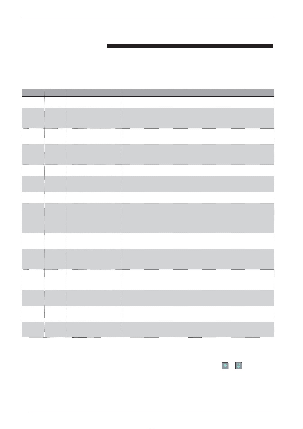
Type Code Cause Description
Sd1 Defrosting level D uring the defrosting procedure, the machine visualises
the message d1 alternated with the temperature.
Sr1 Defrosting error If the defrosting finishes according to maximum time, when the conclusion for the
reaching of temperature threshold, or outside contact, is selected, the machine
shows the sign r1. The message is disactivated by cancelling the alarms, or by
carrying out another, correct defrosting cycle. The alarm relay is not activated.
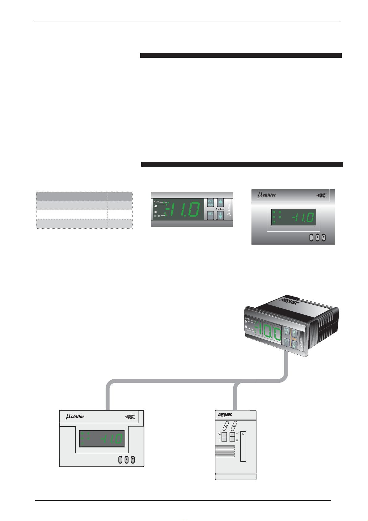
SCn Error of communication with
the remote terminal
In the event of a communication error between the panel on the
machine, and the remote terminal PRD, the message Cn is visualised;
check the connection cable. The alarm relay is not activated.
AH1 high pressure The compressor is immediately switched off, the alarm relays are activated, and the
display flashes. The fans are activated at maximum speed for 60 seconds, to contrast
the alarm situation, then they are switched off. The heat pumps can also indicate the
intervention of the thermal protection of the compressor. The restoration is manual.
AL1 low pressure The alarm leads to the immediate switching off of the compressor, or its non-starting.
The alarm relays are activated, and the display flashes. The restoration is automatic.
AA1 Antifreeze The alarm is sensed by the water outlet probe of the evaporator (SUW). The
alarm immediately switches off the compressor and the fans, while the
alarm relays are activated and the display flashes. The restoration is manual.
AFL FLOW SWITCH The alarm switches off the pump, the compressor and fans. The display
flashes and the alarm relays are activated; The restoration is manual.
AE1, E2,
E3
Probe alarms T h e presence of a probe alarm leads to the disactivation of
the compressor, the fans and the pump; the relay alarms are
activated and the display flashes. The restoration is automatic.
E1: Water inlet probe
E2: Water outlet probe
E3: Coil probe
AE4 Compensation probe alarm T he presence of a probe alarm leads to the disactivation of
the compressor, the fans and the pump; the relay alarms are
activated and the display flashes. The restoration is automatic.
AEU/EO Error of low or high supply
voltage
In the event of a supply voltage that is too low, the message EU appears;
if too high, the indication is EO. In these cases, the correct working
of the unit is no longer guaranteed. In the event of EO alarm, the
compressor, pump and fans are switched off; the restoration is automatic.
AEP/EE Eeprom alarm error A problem in the non-volatile memory of the machine (eeprom). If it is a case
of EE, the unit continues to work until the first loss of power supply. When
power supply is restored, if the error is still present, the display begins to flash,
showing the sign EP, and the unit doesn't start up; the restoration is automatic
AEL Error of line disturbance Appears if a loud noise is present in the power supply. In this case, the fans (if driven
with the DCPX accessory) will begin to work On/Off for the time that the disturbance
continues. The restoration is automatic.
AEr Error of expansion module for
compensation probe
The presence of an expansion module alarm leads to the disactivation
of the compressor, the fans and the pump; the relay alarms are
activated and the display flashes. The restoration is automatic
AHt High temperature of return
water
In the event that the temperature of the return water is higher
than the set limit, the working cycle of the unit is interrupted;
the alarm relay is not activated. The restoration is automatic.
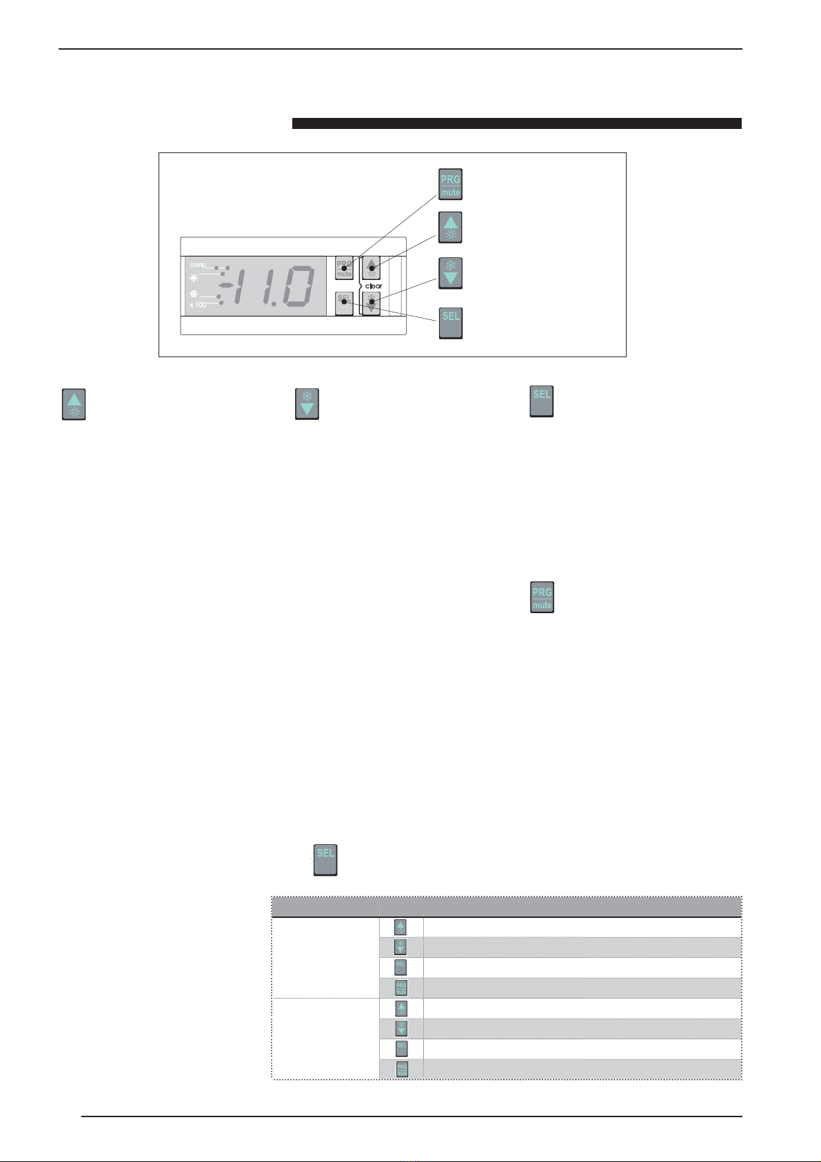
The signalling of particular working states
of the unit, or the emergence of an alarm
condition, are communicated by the micro
chiller controller, with codified messages
visualised on the display; to decode these
messages, use the table below. When an
alarm is activated, the following actions are
generally carried out:
• activation of alarm relay
• flashing of the temperature visualisation on
Key::
S: Signalling
A: ALARM
the display
• visualisation on the display of the alarm
code, alternated with the temperature
With the disappearance of the automatically restored alarms (or the contemporary pressing of
and for five seconds for the manually restored alarms), the following actions are obtained:
• disactivation of the alarm relays;
• suspension of the flashing temperature on the display;
• suspension of the visualisation of the alarm code.
If the alarm condition continues, the procedure for signalling the alarm is repeated.
RESETTING OF THE ALARMS

Características del ajuste electrónico 10
Uso de las teclas 11
Lista de parámetros 12
Ajuste termostatos versiones K 14
ALARMAS 15
Índice
Índice

10
visualización del historial de alarmas
con un indicador rojo (alarmas). Si,
por el contrario, se instala el mando
accesorio de control remoto PRD, es
posible realizar a distancia todas las
funciones del control a bordo de
la máquina. El control dispone de
cuatro teclas multifunción: al pulsar
una o dos teclas al mismo tiempo, es
posible controlar todos los parámetros y
funciones de la unidad.
x100h
SEL
A
L
A
R
M
• PRV
Mando de control
remoto inteligente:
reproduce las
funciones del mando
de la máquina a una
distancia máxima de
150 m.
• PR1
Mando de control
remoto simplificado:
realiza todas las
funciones básicas
a una distancia
máxima de 30 m.
µchiller compact
Características del ajuste
El tablero de mandos de la unidad
permite programar rápidamente los
parámetros de funcionamiento de la
máquina, visualizarlos en cualquier
momento y comprobar inmediatamente
el estado de funcionamiento de la
máquina. El visor está formado por 3
cifras y 4 led que indican el tipo de
funcionamiento, la visualización de los
parámetros programados o medidos,
y de las posibles alarmas activadas.
En la tarjeta se memorizan todas las
programaciones guardadas en cada
modificación y utilizadas cuando se
vuelve a encender la unidad después de
un apagado por falta de tensión.
Con la instalación del mando accesorio
de control remoto PR1 es posible
controlar a distancia el encendido y
apagado, la programación del modo
de funcionamiento (frío-calor), y la
Conexiones remotas
Interfaz del usuario
PRV instalación en pared o
mando (ACCESORIO)
Visor con indicadores luminosos y visor de montaje en tablero.
x100h
SEL
x100h
SEL
Características:
Número de filas 1
Número de columnas 3
Altura carácter (mm) 10

11
(a) Modo Calentamiento
(sólo para bomba de calor):
Si se pulsa la tecla durante más
de 5 segundos, es posible
activar o desactivar el modo de
funcionamiento en enfriamiento.
No se puede pasar directamente
del modo de calentamiento al
modo enfriamiento: si el aparato
está en el modo de enfriamiento,
no ocurrirá nada al pulsar la tecla;
habrá que desactivar antes el modo
enfriamiento.
(b) Modo enfriamiento:
Si se pulsa esta tecla durante
más de 5 segundos, es posible
activar o desactivar el modo de
funcionamiento en enfriamiento.
No es posible pasar directamente
del modo enfriamiento al modo
calentamiento (sólo para bombas
de calor): si el aparato está en
el modo de calentamiento, no
ocurrirá nada al pulsar la tecla;
habrá que desactivar antes el modo
calentamiento.
• Si están instalados el accesorio PR1 o
un interruptor a distancia, sólo será posible
encender y apagar la unidad utilizando
también el mando instalado en la máquina,
si el mando de control remoto está en ON.
Sin embargo, sólo es posible cambiar de
modo utilizando el mando a distancia.
• Durante el funcionamiento normal de la
unidad, en el visor aparece el valor de la
temperatura del agua entrante de la unidad.
(c) Modo de selección:
Al pulsar esta tecla durante más de
5 segundos, en el visor aparece el
mensaje r1, que indica el punto
de ajuste del agua en el modo de
enfriamiento. Pulsando las teclas
(a) y (b) es posible recorrer todos
los parámetros; si entonces se pulsa
la tecla (c) es posible visualizar el
valor del parámetro anteriormente
seleccionado y modificarlo, si se
desea, utilizando las teclas (a) y
(b).
Notas:
• Durante el modo de cambio de los
parámetros y si durante varios segundos no
se producen operaciones, el visor empieza
a parpadear. Si transcurre un minuto sin que
se haya pulsado ninguna tecla, el control
vuelve al modo de funcionamiento normal,
sin guardar los cambios que se hayan podido
realizar.
• La unidad se apaga desactivando los
modos de enfriamiento o calentamiento.
• El visor está formado por 3 cifras, que
muestran automáticamente el punto decimal
entre -19.9 y +19.9 °C; fuera de este rango
de medida, el valor aparece automáticamente
sin decimales, aunque la máquina, en su
funcionamiento, siempre tenga en cuenta la
parte decimal. En funcionamiento normal,
aparece el valor correspondiente a la
temperatura registrada por la sonda SIW,
esto es, la temperatura del agua de entrada
evaporador.
(d) Modo de memorización:
Al pulsar esta tecla, se guardan los
parámetros modificados y se sale
del modo de selección/cambio de
los parámetros.
(a) Modo Calentamiento
(d) Modo de memorización
(c) Modo de selección
(b) Modo enfriamiento
Uso de las teclas
VISUALIZACIÓN/CAMBIO PARÁMETROS (tecla durante más de cinco segundos)
Modo Tecla Función
Visualización Paso al parámetro siguiente
Paso al parámetro anterior
Activación del modo CAMBIO para el parámetro seleccionado
Memorización de la configuración y vuelta al modo de
funcionamiento
Cambio Aumento del valor del parámetro seleccionado
Disminución del valor del parámetro seleccionado
Vuelta al modo VISUALIZACIÓN
Memorización de la configuración y vuelta al modo de
funcionamiento
Para visualizar o modificar los valores
programados para los distintos
parámetros de la unidad, consulte la
tabla de al lado.

12
PARÁMETROS DE FUNCIONAMIENTO (LOS VALORES QUE APARECEN EN LAS VENTANAS SON LOS DE POR DEFECTO):
Lista de parámetros
Visualización Parámetro Frío Frío DCP Calor Calor DCP
Set point frío [°C] 11 11 11 11
Diferencial frío [°C] 2222
Set point calor [°C] 46 46 46 46
Diferencial calor [°C] 2222
Temperatura salida agua (B2) [°C] Visualización. Visualización. Visualización. Visualización.
Temp. ambiente exterior (B4) [°C] Visualización. Visualización. Visualización. Visualización.
Temp. sonda batería cond. (B3) [°C] --- Visualización. Visualización. Visualización.
Número horas compresor Visualización. Visualización. Visualización. Visualización.
Número horas bomba Visualización. Visualización. Visualización. Visualización.
Número horas compresor 2 Visualización. Visualización. Visualización. Visualización.

13
Los siguientes gráficos ilustran cómo el
controlador micro chiller calcula el nivel
de intervención de la máquina según los
distintos ajustes de funcionamiento
programados por el usuario (recuerde que
el procedimiento de cambio y la lista de
parámetros modificables aparecen explicados
en las páginas anteriores).
TERMOSTATO DE FUNCIONAMIENTO
TIA
r1 r2
Po
0 %
100 %
Set
ON
OFF
Termostato Frío a una quebrada
TIA
r4 r3
Po
0 %
100 %
Set
ON
OFF
Termostato Calor a una quebrada
Leyenda:
Po : Potencia rendimiento
TIA : Temperatura entrada agua
r1 : - set frío
r2 : Diferencial en funcionamiento frío
r3 : - set calor
r4 : Diferencial en funcionamiento en calor
U.M. MÍNIMO estándar MÁXIMO
Temperatura agua programada en calentamiento °C 25 46 55
Diferencial termostato de funcionamiento en calentamiento °C 0,3 2 19,9
Temperatura agua programada en enfriamiento °C 71125
Diferencial termostato de funcionamiento en enfriamiento °C 0,3 2 19,9
CALIBRADO ESTÁNDAR Y RANGO DE CALIBRADO DE LOS DISPOSITIVOS DE AJUSTE

14
Ajuste termostatos versiones K
0
15
30
45
60
75
90
°C
30
20
10
0
-10
-20
-30
°C
TLR / TSRE TMA
TLRTLR
TLRTSRE
TLRTMA
TLRTLR
TLRTSRE
TLRTMA
TLRTLR TLRTSRE
TLRTMA TLRTMA
TLRTSRE
TLRTLR
Termostato Valor por defecto
TMA Termostato temperatura mínima aire exterior 5°C
TLR Termostato de funcionamiento resistencia 35°C
TSRE Termostato de seguridad 60°C
En las versiones K, la unidad está equipada
con resistencia eléctrica (en las unidades
más pequeñas, la resistencia está incluida
como accesorio y se monta en el exterior).
El funcionamiento de la resistencia no lo
controla la tarjeta microchiller, sino un grupo
de tres termostatos, que activan la resistencia
eléctrica según los siguientes parámetros:
• Temperatura agua acumulación
• Temperatura aire exterior
• Límite de seguridad para la temperatura
del agua
En la tabla de más arriba aparecen los ajustes
por defecto de los distintos termostatos;
la resistencia estará activa cuando la
temperatura externa (TMA) y la del agua
dentro de la acumulación (TLR) sean
inferiores a los ajustes programados en los
termostatos correspondientes.
Todos los ajustes de los termostatos de
control de la resistencia eléctrica pueden
ser modificados por el usuario tal y como se
explica a continuación.
ATENCIÓN: el termostato de seguridad se
calibra y bloquea durante la fabricación de
la unidad; toda manipulación del mismo
conllevará la anulación de la garantía.
Para modificar el ajuste de los termostatos bastará con
girar el selector hasta el valor de temperatura deseado.
NOTA: El termostato de funcionamiento resistencia y
el de seguridad son iguales, pero llevan una etiqueta
de identificación con las siglas TLR (Termostato de
funcionamiento) o TSRE (Termostato de seguridad)
Posición termostatos dentro de las unidades ANZ K
Modelos ANZK 0207 - 0257 - 0307 - 0417 - 0507 - 0807 - 0907
Modelos ANZK 1007 - 1507 - 2007
Cambio ajustes termostatos en los modelos ANZ K
ATENCIÓN:
El termostato de funcionamiento resistencia y el
de seguridad son iguales, pero llevan una etiqueta
de identificación con las siglas TLR (Termostato
de funcionamiento) o TSRE (Termostato de
seguridad).
Las posiciones de los termostatos que aparecen
en esta página sirven sólo como ejemplo;
antes de cualquier intervención en el ajuste
de los termostatos, compruebe su etiqueta
identificativa.
El termostato de seguridad TMA es de rearme
automático: cuando interviene, sólo apaga la
resistencia.
Recuerde que si se manipula el
termostato de seguridad, se anulará
automáticamente la garantía de la
unidad.

15
Alarmas
Tipología Código Causa Descripción
Sd1 Estado de desescarche Durante el desescarche la máquina muestra el
mensaje d1 alternativamente a la temperatura.
Sr1 Error de desescarche Si el desescarche acaba porque se ha alcanzado el tiempo máximo
cuando, sin embargo, se ha seleccionado el final por alcance del
umbral de temperatura o por contacto exterior, en el visor aparece el
mensaje r1. El mensaje se desactiva cuando se cancela la alarma o
se ejecuta otro ciclo correcto de desescarche. El relé de alarma no se activa.
SCn Error de comunicación con el
terminal remoto
En caso de error de comunicación entre el tablero de la
máquina y el terminal remoto PRD aparece el mensaje Cn;
compruebe el cable de conexión. El relé de alarma no se activa.
AH1 Alta presión El compresor se apaga inmediatamente, se activan los relés de alarma
y el visor parpadea. Los ventiladores se activan a la velocidad máxima
durante 60 s, para hacer frente a la situación de alarma; a continuación
se apagan. En las bombas de calor puede indicar también la activación
de la protección térmica del compresor. Se reajusta de forma manual.
AL1 Baja presión La alarma apaga inmediatamente el compresor, o evita que se encienda; se
activan los relés de alarma y el visor parpadea. Se reajusta de forma automática.
AA1 Anticongelante La alarma se detecta mediante la sonda de agua salida evaporador (SUW).
La alarma apaga inmediatamente el compresor y los ventiladores; se
activan los relés de alarma y parpadea el visor. Se reajusta de forma manual.
AFL Flujostato La alarma apaga la bomba, el compresor y los ventiladores; se activan
los relés de alarma y parpadea el visor. Se reajusta de forma manual.
AE1, E2,
E3
Alarmas sonda Al activarse una alarma sonda, se desactivan el compresor, los ventiladores y la bomba;
el relé de alarma se activa y parpadea el visor. Se reajusta de forma automática.
E1: sonda entrada agua
E2 : Sonda salida agua
E3 : Sonda batería
AE4 Alarma sonda compensación Al activarse una alarma sonda, se desactivan el compresor, los ventiladores y la bomba;
el relé de alarma se activa y parpadea el visor. Se reajusta de forma automática.
AEU/EO Error de baja o alta tensión de
alimentación
En caso de tensión de alimentación demasiado baja, aparece el mensaje EU;
si la tensión es demasiado alta, aparece EO. En estos casos, no se garantiza
el funcionamiento correcto de la unidad. En caso de alarma EO se apagan el
compresor, la bomba y los ventiladores; se reajusta de forma automática.
AEP/EE Error alarma eeprom Es un problema en la memoria no volátil de la máquina (eeprom). Si se trata de
EE, la unidad sigue funcionando hasta la primera interrupción de la alimentación.
Cuando vuelva la tensión, si persiste el error, el visor empezará a parpadear con
el mensaje EP y la unidad no se encenderá; se reajusta de forma automática.
AEL Error de irregularidades de
línea
Aparece si hay fuertes irregularidades en la alimentación. En tal caso, los ventiladores,
se están controlados por el accesorio DCPX, empezarán a funcionar On/Off mientras
duren las irregularidades. Se reajusta de forma automática.
AEr Error módulo de expansión
por sonda de compensación
Al activarse una alarma módulo expansión, se desactivan el
compresor, los ventiladores y la bomba; el relé de alarma se
activa y parpadea el visor. Se reajusta de forma automática.
AHt Alta temperatura agua de
retorno
Si la temperatura del agua de retorno del sistema sobrepasa el
límite fijado, se interrumpe el ciclo de funcionamiento de la unidad;
el relé de alarma no se activa. Se reajusta de forma automática.
El controlador micro chiller informa de
determinados estados de funcionamiento
de la unidad o de que se ha producido una
situación de alarma mediante mensajes
codificados en el visor. Consulte la tabla de
más abajo para descodificar dichos mensajes.
Al producirse una alarma, se producen, por
lo general, las siguientes acciones:
• El relé de alarma se activa
• La visualización de la temperatura del
Leyenda:
S: Señal
A: Alarma
visor parpadea
• Aparece en el visor el código de
alarma alternativamente a la temperatura
Al desaparecer las alarmas de reajuste automático o al apretar simultáneamente y durante
cinco segundos, en el caso de alarma de reajuste manual, se producen las acciones siguientes:
• El relé de alarma se desactiva.
• Deja de parpadear la visualización de la temperatura en el visor.
• Desaparece la indicación del código de alarma.
Si la situación de alarma perdura, se repetirá el procedimiento de indicación de alarma.
REAJUSTE DE LAS ALARMAS

AERMEC S.p.A.
37040 Bevilacqua (VR) - Italy
Via Roma, 44 - Tel. (+39) 0442 633111
Telefax (+39) 0442 93730 – (+39) 0442 93566
www.aermec.com
The technical data in the following documentation are not binding.
Aermec reserves the right to make all the modifications considered
necessary for improving the product at any time.
carta riciclata
recycled paper
papier recyclé
recycled Papier
ISO 9001 - Cert. n° 0128/4
Los datos técnicos contenidos en este documento no son vinculantes.
AERMEC se reserva la facultad de aportar, en cualquier momento, todas las
modificaciones consideradas necesarias para la mejora del producto.
Table of contents
Languages:
Other AERMEC Controllers manuals

AERMEC
AERMEC WRCB User manual

AERMEC
AERMEC pCO3 User manual

AERMEC
AERMEC HMI-1 User manual

AERMEC
AERMEC HMI-BHP User manual

AERMEC
AERMEC NXW Parts list manual

AERMEC
AERMEC WRC50 User manual

AERMEC
AERMEC Multichiller-Evo User manual

AERMEC
AERMEC CC2 Guide

AERMEC
AERMEC WMT21 User manual

AERMEC
AERMEC EXTK PRO User manual