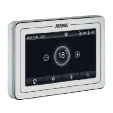
AERMEC WRC50 User manual

23/02 – 5385746_00
Translation of Original instructions
User manual
www.aermec.com
WRC50
WIRED CONTROLLER

Dear customer,Thank you for choosing an Aermec product. It is the fruit of many years of experience and special design studies and has been made of the highest grade
materials and with cutting edge technology.In addition, all our products bear the CE mark indicating that they meet the requirements of the European Machine Direc-
tive regarding safety. The quality level is being constantly monitored, so Aermec products are synonymous with Safety, Quality and Reliability.The data may undergo
modications considered necessary for the improvement of the product, at any time and without the obligation for any notice thereof.
Thank you again.
Aermec S.p.A.
COMPANY CERTIFICATIONS
SAFETY CERTIFICATIONS
This marking indicates that this product should not be disposed with other household wastes throughout the EU. To prevent possible harm to the envi-
ronment or human health from uncontrolled disposal of Waste Electrical and Electronic Equipment (WEEE), please return the device using appropriate
collection systems, or contact the retailer where the product was purchased. Please contact your local authority for further details. Illegal dumping of
the product by the user entails the application of administrative sanctions provided by law.
All specications are subject to change without prior notice. Although every eort has been made to ensure accuracy, Aermec shall not be held liable for any errors or
omissions.

3
TABLE OF CONTENTS
1. Electrical device warnings.............................................................p.4
GENERAL WARNINGS ............................................................................p.4
WARNINGS FOR THE USER ..................................................................p.4
WARNINGS FOR THE INSTALLER........................................................p.4
2. Operation notices ..............................................................................p.5
3. Display......................................................................................................p.5
LCD of the Wired Controller................................................................p.5
LCD Display instruction........................................................................p.6
4. Installation and start-up.................................................................p.7
Instruction of wired controller ..........................................................p.7
Commissioning.................................................................................... p.11
5. Operation Instructions................................................................. p.13
ON/OFF ................................................................................................... p.13
Mode Setting ........................................................................................ p.13
Temperature Setting.......................................................................... p.14
Fan Setting............................................................................................. p.14
Timer Setting ........................................................................................ p.14
Set delivery n (swing)...................................................................... p.16
Quiet Function Setting...................................................................... p.16
Sleep Setting......................................................................................... p.16
Energy Saving Function Setting .................................................... p.16
Filter clean reminder setting........................................................... p.18
X-fan Setting ......................................................................................... p.18
I-Demand Setting................................................................................ p.18
Absent Setting...................................................................................... p.18
Shielding status ................................................................................... p.18
Child Lock function............................................................................. p.18
Inquiry of Indoor Temperature with one button..................... p.18
Setback Function................................................................................. p.18
Set the indoor unit address (CC2) ................................................. p.19
Set the indoor unit address (BMS) ................................................ p.19
6. Errors Display..................................................................................... p.20
Table of display error codes for LPG unit.................................... p.20

4
1 ELECTRICAL DEVICE WARNINGS
GENERAL WARNINGS
— Read carefully these general safety precautions before installing the air condi-
tioning devices and ensure that the installation is performed correctly.
— Failure to observe these instructions can cause damages to property or people's
injuries, which may b e serious depending on the circumstances.
— Aermec S.p.A. will in no case be liable for any damages to property and/or per-
sons caused by improper operations such as: incorrect installations, debugging
or maintenance not carried out, non-compliance with the installation regula-
tions foreseen in the country where the device will be installed or non-compli-
ance with the rules contained in this manual.
— Refer to the national regulations for the installation: the device must be in-
stalled in compliance with national plant engineering rules.
WARNINGS FOR THE USER
— It is not recommended for persons (including children) with limited physical,
sensorial or mental abilities, or operators without experience and knowledge,
to use the machine unless in the presence of a person responsible for their safe-
ty capable of monitoring them and of providing adequate instructions for use.
Do not allow children to play with the appliance.
— All illustrations and information contained in this manual are purely indicative;
for the actual command of the device functions, refer to the controller display
(if tted).
— In order to improve the product, we reserve the right to modify or revise this
document without prior notice; therefore remember to periodically verify the
presence of new versions.
— To prevent electric shock or re accidents:
1. Do not operate the air conditioner with wet hands.
2. Do not disassemble the device or remove its internal parts.
3. Do not modify or repair the air conditioner by yourself.
4. Do not move or re-install the device by yourself.
5. Do not use ammable materials near the device.
— To clean the device, do not use organic solvents, such as paint thinners. Possible
result: damages, electric shock or re accidents.
WARNINGS FOR THE INSTALLER
— This device cannot be used on its own. Also refer to the user manuals of the
outdoor/indoor unit.
— The electric connections and installation of the device must only be performed
by individuals with the technical-professional requisites for installation, trans-
formation, expansion and maintenance of the systems and able to check the
same for safety and functionality purposes. In this manual they will be generi-
cally referred to as "Sta with specic technical skill".
— Improper installation or assembly of the device could cause electrocution,
short-circuits, leaks and res.
— Use exclusively optional devices and spare parts approved by Aermec S.p.A..
— Ensure that the electrical power supply complies with the parameters included
in this manual. A power supply that is dierent from the recommended one can
cause damage.
— Ensure that all connections are performed according to the instructions in this
manual. Incorrect connections could cause communication malfunctioning.
— Ensure to be able to use the correct communication ports, otherwise the con-
nection may not work properly.
— The connected communication line must be protected with electrical tape to
prevent oxidation and short-circuits.
WARNING: Do not install the device in a location where it could be aected
by inammable gas leaks or deposits of materials which are inammable,
explosive, poisonous, corrosive or hazardous substances. Risk of re or ex-
plosion. Install the device in a place with minimal levels of dust, fumes,
air humidity and corrosive agents, and where it is not exposed to direct
sunlight or adverse weather conditions.
5
2 OPERATION NOTICES
1. The power supply for all indoor units must be unied.
2. Never install the wired controller in the moist circumstance or expose it directly under the sunlight.
3. Never beat, throw, and frequently disassemble the wired controller and the wireless remote controller.
4. Never operate the wired controller and the wireless remote controller with wet hands.
5. This product is applicable to LPG unit whose outdoor unit and indoor unit communicate with each other by live line and neutral line.
6. When two wired controllers control one (or more) indoor unit(s), the address of wired controller should be dierent.
3 DISPLAY
Fig. 3.1: Outside View of the Wired Controller
2
3 D
3.1 LCD OF THE WIRED CONTROLLER
Fig. 3.2: LCD graphics of wired controller
2
3 D
1 2 3 4 5 6 7 8 9 10
24
25
27
29
31
26
23 22 21 20 19 18 17 16 15 14 13
28
30
32
33
12
11

6
3.2 LCD DISPLAY INSTRUCTION
N. Symbols Functions
1FUNCTION NOT AVAILABLE
2Child Lock
3
2
Slave wired controller (address of wired controller is 02)
4One wired controller controls multiple indoor units
5Outdoor unit defrosting status
6Shielding status
7Current wired controller connects master indoor unit
8FUNCTION NOT AVAILABLE
9
FUNCTION NOT AVAILABLE
10
FUNCTION NOT AVAILABLE
11 Timer zone: Display system clock and timer status
12 Current set fan speed
13 Absence function
14
FUNCTION NOT AVAILABLE
15 Remind to clean the lter
16 X-FAN function
17 FUNCTION NOT AVAILABLE
18 Save status of indoor unit
19
FUNCTION NOT AVAILABLE
20 I-DEMAND function, Indoor unit optional function
21 Quiet status (including Quiet and Auto Quiet two status)
22 Night-time comfort function
23 Left & Right Swing Setting
24 Up & Down Swing Setting
25
3 D
FUNCTION NOT AVAILABLE
26 FUNCTION NOT AVAILABLE
27 Heating mode
28 FUNCTION NOT AVAILABLE
29 Dry mode
30 Fan mode
31 Auto mode
32 Cooling mode
33 It shows the value of temperature, and displays the current type of value
NOTE: When wired controller is connected with dierent indoor units, some functions will be dierent.

7
4 INSTALLATION AND STARTUP
Fig. 4.1: Dimensions of Wired Controller
Fig. 4.2: Parts and Components of Wired Controller
N. 1 2 3 4
Name Wired Controller Self-tapping screw ST3.9×25 MA Screw M4×25 Soleplate of the Wired Controller
Quantity 1421
4.1 INSTRUCTION OF WIRED CONTROLLER
4.1.1 Requirements for model selection of communication wire
Fig. 4.3: Length of communication wire
L= L01+L02+L1+L2+....+L(n-1) (n≤16)
1 2 3 n
L1 L2 L(n-1)
MASTERSLAVE
L02 L01
Indoor unit Indoor unit Indoor unit Indoor unit
Wired panel
Cable type Max lenght Size Note
Standard 2-pole cable with PVC sheath (60227 IEC
52 / 60227 IEC 53) L ≤ 250 m From 2 x 0,75 to 2 x 1,25
mm2
(1) Total length of communication line can’t exceed 250m.
(2) The cord shall be Circular cord (the cores shall be twisted together).
(3) If unit is installed in places with intense magnetic eld or strong interference, it is necessary to use shielded
wire.

8
4.1.2 Requirements for installation
1. It is not allowed to install the wired controller in the wet place.
2. It is not allowed to install the wired controller in the place with direct sunlight.
3. It is not allowed to install the wired controller near the high-temperature object or the place is likely to be spattered with water.
4. It is not allowed to install the wired controller outdoor.
4.1.3 Requirements for wired connection
Network connecting methods between wired controller and indoor unit are as below:
Fig. 4.4: one wired controller controls one indoor unit
1. D1 D2 or N(1) 2 3
2. H1 H2
12
Indoor unit
Outdoor unit
Fig. 4.5: two wired controllers control one indoor unit
1. D1 D2 or N(1) 2 3
2. H1 H2
12
Outdoor unit
Indoor unit

9
Fig. 4.6: one wired controller controls multiple LPG unit indoor units simultaneously
1. N(1) 2 3
2. H1 H2
1 2 n
1 2 n
121212
Outdoor unit Outdoor unit Outdoor unit
Wired panel
Indoor unit Indoor unit Indoor unit
Fig. 4.7: two wired controller control multiple LPG indoor units simultaneously
1. N(1) 2 3
2. H1 H2
1 2 n
1 2 n
121212
MASTERSLAVE
Outdoor unit Outdoor unit Outdoor unit
Indoor unit Indoor unit Indoor unit
Wired panel
Instruction for wire connection:
1. The wiring methods in g. 4.4, g. 4.5, g. 4.6 and g. 4.7 can be adopted for the wired controller connecting LPG unit.
2. When one (or two) wired controller(s) control(s) multiple indoor units simultaneously, the wired controller can connect to any one indoor unit.The total quantity of indoor
unit controlled by wired controller can’t exceed 16 sets, and the connected indoor unit must be within the same indoor unit’s network. Wire controller must set quantity
of group control indoor units. Please refer to Parameter Setting“P14”.
3. When two wired controllers control one (or more) indoor unit(s), the addresses of those two wired controllers should be dierent. Please refer to Parameter Setting “P13”.
4. The terminal of the wire controller is non-polarized and cannot be connected to strong electric.

10
4.1.4 Installation
Fig. 4.8: Installation of Wired Controller
Fig. 4.8 shows a simple installation course of wired controller, and the following points should be noted:
1. Before installation, please cut o the power supply of indoor unit, it is not allowed to operate with power supply;
2. Pull out the 2-core twisted pair inside the installation hole in the wall, and thread the wire through the hole in the back of soleplate of wired controller;
3. Stick the soleplate of wired controller on the wall, and use Self-tapping Screw ST3.9×25 MA or screw M4×25 to x the soleplate with the installation hole of wall;
4. Connect the 2-core twisted pair to wiring terminal H1 and H2, and then tighten the screw;
5. Arrange the wires in the back of panel, and then buckle the panel of wired controller with the soleplate of wired controller.
4.1.5 Disassembly
Fig. 4.9: Disassembly of wired controller

11
4.2 COMMISSIONING
4.2.1 Set a Master unit
Under O status, long press“MODE” button for 5s to set the corresponding indoor unit of wired controller as master indoor unit.
If the system mode priority is the master-slave mode, “ ”icon will be light after nishing setting.
NOTE: There is a master indoor unit in a system, other slave indoor units can be set as master unit, in which case, the original master unit will become a slave unit.
4.2.2 Display indoor unit operating parameters
Unit parameters can be checked in unit On or O status:
1. Press“FUNCTION”button for 5s to enter the interface of viewing unit parameters.“C00” is displayed in temperature zone.
2. Press“+” or “-”button to select parameter code.
3. Press“ENTER” button to return to last step until exits viewing parameters.
The parameter enquiry list is as following:
Index
parameter Function Range Description of operating parameter
C07 Display the room temperature
-
Enter viewing: press“MODE” button in “C07”status. Press“+” or“-” button to select indoor unit.
Temperature zone: displays current indoor unit project number;
Timer zone: displays outdoor ambient temperature.
C08 View Filter Clean Reminder time 4-416: days Timer zone: displays Filter Clean Reminder time
C09 Display the address of the wired
panel 01, 02 Timer zone: displays the address of wired controller
C11 View the indoor unit quantity 01-16 This parameter indicates (in the timer zone) the number of units in any group connected to the wired panel
C12 Display external temperature;
-
This parameter indicates (in the timer zone) the temperature of the external air
C17 View indoor relative humidity 0~100%: relative
humidity
Press“MODE” button to enter into the review interface of indoor relative humidity under“C17”status. Press
“+”or “-” button to switch the number of indoor unit.
Temp area: display current indoor unit’s project number.
Timer zone: display indoor relative humidity.
C23 Version inquiry
-
Timer zone: program version of the current wired controller
NOTE:
1. Under parameter viewing status,“FAN”, “TIMER”, and“SWING” buttons are invalid. Press“ ” button to go back to the homepage, while not to turn on/o the unit.
2. Under parameter viewing status, the signal from remote controller is invalid.

12
4.2.3 Activation of indoor unit operating parameter modication menu
Unit parameters can be set in unit On or O status:
1. Long press“FUNCTION”button for 5s and the temperature zone displays “C00”; long press “FUNCTION” button for another 5s to enter the interface of setting wired con-
troller parameters. “P00”is displayed in temperature zone.
2. Press“+” or “-”button to select parameter code. Press“MODE”button to enter parameter setting. At that time, parameter value is blinking.
3. Press“+” or “-”button to adjust the parameter value and press“ENTER” button to nish setting.
4. Press“ENTER” button to return to last step until exists setting parameters.
The parameter setting list is as following:
Index
parameter Function Range Default Description of operating parameter
P11 Enable infra-red remote controls 00: NOT enabled
01: enabled
01
This parameter is used to enable or disenable the infra-red remote controls
on the system (if envisaged); this parameter can ONLY be set from the panel
of the master indoor unit.
P13 Set the address of the wired panel 01: MASTER panel
02: SLAVE panel
01
This parameter is used to set the address to be assigned to the wired panel;
this parameter is used if two panels are connected to the same machine or
the same group in order to set two dierent addresses.
P14 Set the number of units in the
group
00: test disenabled
01-16: group with ... units
01
This parameter performs a test on the group (if a group has been created)
in order to specify how many indoor units belong to it. This test checks
whether the number set in the parameter matches the number of units
detected by the system in the group; if this function is disenabled (value 00)
and the wired panel manages a group, no alarms will be displayed for any
malfunctions in this group.
P16 Set unit of measure 00: °C
01: °F
00
This parameter species which unit of measure is used to display
temperatures.
P30 Set static pressure of indoor fan
motor
01-09: static pressure level of
indoor fan motor
05 -
P42 Setting the serial address of the
indoor unit
1~36 (for CC2) / 1~255 (for
BMS)
---
Setting indoor unit address when it is connected to a CC2 centralized
controller or a third party management system (BMS).
P46 Clear Filter / Clean accumulated
time
00: do not clear
01: clear
00 -
P71 Set Setback Function 01: deactivated
01: activated
00 -
P72 Temperature upper limit for
Setback Function
20~30°C
68~86°F)
26°C
(79°F)
When temperature unit is °C, temperature upper limit – temperature lower
limit ≥ 4°C;
When temperature unit is °F, temperature upper limit – temperature lower
limit ≥7°F.
P73 Temperature lower limit for Setback
Function
16~26°C
61~79°F)
20°C
(68°F)
P74 When inserting the card, whether
to resume to previous status
00: no
01: yes
01
When it is set as 00, it will keep the status after inserting the gate control
card, that is, if it is OFF status when pulling out the card, when inserting the
card, it is still OFF status.
P83 Temperature control method under
cooling mode
00: Ambient temperature
control
01:Temperature and humidity
correction control
Depending on Indoor
unit
NOTE: Only applicable to the unit which is with temperature and humidity
correction control function
P87 Interval of Set temperature in
Celsius
00: 1°C
01: 0.5°C
01
01: The set temperature will be adjusted at 0.5°C.
00: The set temperature will be adjusted at 1°C.
NOTE:
1. Under parameter setting status,“FAN”, “TIMER”and“SWING” button are invalid. Press“ ” button to go back to home page, but not turning on/o the unit.
2. Under parameter setting status, the signal from remote controller is invalid.
WARNING: accidental modication of these parameters may cause malfunctions or block the entire system; reminder: setting or modifying these parameters must
ONLY be performed by the technical assistance service or personnel having the necessary technical skills.

13
5 OPERATION INSTRUCTIONS
5.1 ON/OFF
Press “ ” button to turn on the unit. Press “ ” button again to turn o the unit.
The interfaces of “ON/OFF”status are shown in Fig. 5.1 and 5.2.
Fig. 5.1: Interface of ON status
Fig. 5.2 Interface of OFF status
5.2 MODE SETTING
Under On status, pressing“MODE” button can set mode circularly as:
A Auto
B Cooling
C De-Humidication
D Ventilation
E Heating
F FUNCTION NOT AVAILABLE
G FUNCTION NOT AVAILABLE
H FUNCTION NOT AVAILABLE
3 D
ABCD E F GH
Or:
A Auto
B Cooling
C De-Humidication
D Ventilation
E Heating
ABCD E
NOTE:
1. The available modes are dierent for dierent models, the wired controller will automatically select mode setting range according to the model of indoor unit.
2. Under Auto mode, if the indoor unit is running under Cooling, the icons“ ” and “ ” will light up; if the indoor unit is running under Heating, the icons“ ” and “
”will light up.

14
5.3 TEMPERATURE SETTING
Press“+” or “-” button under on status to increase or decrease set temperature by 0.5°C/1°C or 1°F; hold “+” or “-” button to increase or decrease set temperature by 0.5°C/1°C
or 1°F every 0.3s. Please refer to "4.2.3Activation of indoor unit operating parameter modication menup.12" Parameter Setting for the setting method of the temperature
setting interval in Celsius.
n Dry mode, when temperature is 16°C or 61°F, continuously press “-”button twice to decrease temperature to 12°C or 54°F (when save function is activated, the temperature
in Dry mode can’t be adjusted to 12°C or 54°F).
When the control method under Dry mode is humidity control, press “+” or“-” button to adjust the set humidity at 5% intervals.
The humidity setting range is 45%-75%, and the default value is 65%. The humidity control method under Dry mode can only be set for the unit with this function.
Please refer to "4.2.3Activation of indoor unit operating parameter modication menup.12" Parameter Setting for the setting method.
NOTE:
1. Only when the wired controller controls LPG indoor units can the setting temperature be adjusted by pressing“+” or “-”under Auto mode.
2. When Absence function is activated, the setting temperature cannot be adjusted by pressing“+” or“-”.
5.4 FAN SETTING
Under On status, pressing“FAN”button can set fan speed circularly as:
AUTO
In unit on status, press “FUNCTION” button to switch to Turbo function with Turbo function icon “TURBO” blinking, and then press “ENTER” button to start or cancel Turbo
function.
When Turbo function is activated, Turbo function icon “ ”will be bright.
NOTE:
1. Under Dry mode, fan speed is low and can’t be adjusted.
2. If indoor unit’s fan speed is set auto, indoor unit will change fan speed automatically according to room temperature in order to make the room temperature more stable
and comfortable.
5.5 TIMER SETTING
The wired controller is equipped with two kinds of timer: general timer and clock timer.
General timer is factory defaulted setting. Please refer to "4.2.3Activation of indoor unit operating parameter modication menup.12" Parameter Setting for the timer
setting way.
5.5.1 General timer
Unit On/O after a desired hour can be set through general timer.
Set Timer: when timer is not set, press“TIMER” button to enter timer setting and“HOUR” icon is blinking. Press“+” or “-” button to adjust timer time. Press“TIMER” button to
save the setting and then exit setting.
Cancel Timer: when timer is set, press“TIMER” button to cancel it.
Timer setting range: 0.5-24h. Press“+”or “-” button to increase or decrease timer time by 0.5h; hold “+”or “-” button to increase or decrease timer time by 0.5h every 0.3s.
5.5.2 Clock setting
Clock display: when the timer setting way is clock timer, timer zone displays system clock in unit On and O status. The clock can be set at this time.
Clock setting: long press“TIMER” button for 5s to enter clock setting. Press“+”or “-”button to increase or decrease clock time by 1min; hold“+” or “-”button for 5s to increase
or decrease clock time by 10min; hold“+” or “-”button for 10s to increase or decrease clock time by 60min.
Press“ENTER” button or “TIMER”button to save the setting and then exit setting.
5.5.3 Clock timer
Unit On/O at a certain time can be set through clock timer.
Timer Setting:
1. Press“TIMER” button to enter timer on setting and the“ON”icon is blinking.
2. Press“+” or “-”button to adjust unit On time. Press“ENTER” button to nish setting.
3. Before pressing“ENTER” button, pressing“TIMER” button can save unit On time and then switch to unit O time setting with“OFF”icon blinking.
4. Press“+” or “-”button to adjust unit O time. Press“ENTER”button to nish setting.
Cancel Timer:
Press“TIMER” button to enter timer setting; press “TIMER”button again to switch to the setting of unit ON time or unit O time; press“ENTER”button to cancel timer.
Press “+” or “-” button to increase or decrease timer time by 1min; hold “+” or “-” button for 5s to increase or decrease timer time by 10min; hold “+” or “-” button for 10s to
increase or decrease 60min.

15
Clock Timer setting is as shown in Fig. 5.3:
Fig. 5.3: Unit On/O time setting in unit On status
1 Unit is on and timer is not set
2 Press "TIMER" button to set unit On time
3 Press“+” or “-” button to adjust unit On time
4 Press TIMER button to switch to unit O time setting
5 Press“+” or “-” button to adjust unit O time
6 Press "ENTER" button to nish setting
1 2
4 3
5 6

16
5.6 SET DELIVERY FIN SWING
In unit on status, up & down swing function and left & right swing function can be set.
Up & down swing function:
Up & down swing function has two modes: simple swing mode and xed-angle swing mode. In unit o status, press“SWING”button and “+”button together for 5 seconds to
switch between simple swing mode and xed-angle swing mode. Up & down swing icon“ ”will blink during switching.
1. When simple swing mode is set in unit on status, press “SWING”button to start or stop up & down swing.
2. When xed-angle swing mode is set in unit on status, press“SWING”button to adjust swing angle circularly as below:
CLOSED
Left & right swing function:
In unit on status, press“FUNCTION”button to switch to left & right swing function with left & right swing icon“ ”blinking, and then press “ENTER”button to start or cancel
left & right swing. When left & right swing is activated, left & right swing icon “ ”will be bright.
5.7 QUIET FUNCTION SETTING
Quiet function: decrease the noise of indoor unit and achieve the quiet eect. Quiet function has two modes: Quiet mode and Auto Quiet mode. It is available only in Auto,
Cooling, Dry, Fan, Heating,.
Turn on Quiet Function: press “FUNCTION” button to turn to Quiet function and then Quiet icon “ ” or auto quiet icon “ ” is blinking. At this moment, press “+” or “-”
button to switch between quiet and auto quiet, and then press“ENTER”button to activate.
Turn o Quiet Function: press“FUNCTION”button to turn to Quiet function and then press “ENTER” button to cancel Quiet function.
NOTE:
1. When Quiet function is enabled, indoor unit will operate at quiet fan speed. Fan speed is lowered so as to reduce the noise of indoor fan motor.
2. When Auto Quiet function is enabled, indoor unit will change fan speed automatically according to room temperature. After room temperature reaches a set point, unit
will operate at quiet fan speed.
5.8 SLEEP SETTING
Night-time comfort function: in this mode, the unit will operate according to the preset sleep curve to provide comfortable sleep environment.
Activating / Deactivating the Night-Time Comfort Function: in unit On status, press “FUNCTION” button to switch to Sleep function and the Sleep icon ““ ” will blink.
Press“ENTER” button to turn on this function. When Sleep function is activated, ““ ”icon is bright and quiet or auto quiet mode is also activated.
Under Auto or Fan the Sleep function is not available.
5.9 ENERGY SAVING FUNCTION SETTING
Energy Saving function: Air conditioner can be operated in small temperature range by setting the minimum temperature under Cooling and Dry modes and setting maxi-
mum temperature under Heating mode. Thus, energy saving can be realized.
Start up Energy-Saving function for Cooling: When the unit is o, simultaneously press “TIMER” and “+” buttons for 5s, the buzzer will give out a sound and then unit will
enter into Save setting mode.“ ”icon is blinking. Mode icon is on. Press“MODE”button to switch to Cooling or Dry mode. Press“+” or “-” button to adjust the temperature
limit for Save function; press“ENTER” button to start up Save function.

17
Fig. 5.4 shows how to set Save function for Cooling:
Fig. 5.4: Energy Saving Function Setting for cooling
1 Press TIMER and “+” buttons for 5 seconds and set Energy-Saving function in OFF status
2 Press MODE button and select Cooling or Dry mode
3 Press“+” or “-” button to adjust the minimum temperature
4 Press Enter button to activate Energy-Saving function
1 2
4 3
Start up Energy-Saving function for Heating: When the unit is o, simultaneously press“TIMER”and“+”buttons for 5s, the buzzer will give out a sound and then unit will en-
ter into Energy-Saving setting mode.“ ” icon is blinking. Mode icon is on. Press“MODE”button to switch to Heating mode. Press“+” or “-”button to adjust the temperature
limit for Save function. Press “ENTER” button to start up Save function. After starting up save function, it will display “ ”icon for all modes under on and o status.
Cancel Energy-Saving function: When the unit is o, press“TIMER”and“+”buttons for 5s to enter into save setting, press“ENTER”button to cancel Save function of all modes.
NOTE: When the Save function is turned on and then set temperature exceeds the limit value for Save function, “ ” icon blinks three times and then buzzer will give out two
sounds successively.

18
5.10 FILTER CLEAN REMINDER SETTING
Filter Clean Reminder Function: Unit will remember its own operating time.When the setting time is up, this function will remind you to clean the ler. A dirty lter will result
in bad heating and cooling performance, abnormal protection, bacteria gathering, etc.
Turn on Filter Clean Reminder Function: When unit is on, press “FUNCTION” button and select Filter Clean Reminder. “ ” icon will blink. Press “+” or “-” button to adjust
the cleaning level, of which the range is 00, 10-39. Press“ENTER”to turn on this function.
Turn o Filter Clean Reminder Function: When unit is on and this function has been turned on, press“FUNCTION” button and select Clean. Then “ ” icon will blink. Set
the cleaning level as 00 and press“ENTER” function to cancel this setting.
When Filter Clean Reminder time is up,“ ” icon will light up to remind you to clean the lter. There are two ways to cancel lter clean reminding:
1. Press “ ” button twice within one second to cancel reminding and it will retime according to the original cleaning level.
2. Press“FUNCTION” button to turn to Filter Clean Reminder Function, then press “ENTER”to cancel reminding, and it will retime according to the original cleaning level. The
clean reminding can be cancel only when you didn’t reset the cleaning level under the setting of Filter Clean Reminder Function.
NOTE:
Description on cleaning level: When setting the Filter Clean Reminder Function, timer zone will display 2 digits, of which the former indicates the pollution degree of oper-
ating place and the latter indicates the operating time of indoor unit.
There are 4 types of situations:
Pollution level of the environment where
the indoor unit is installed Description of Levels
Turn o Clean reminding Timer zone shows 00
Light Pollution The former digit shows 1 while the latter one shows 0, which indicates the accumulating operating time is 5500 hours. Each time the
latter digit increases 1, the operating time increases 500 hours. When it reaches 9, it means the operating time is 10000 hours.
Medium Pollution The former digit shows 2 while the latter one shows 0, which indicates the accumulating operating time is 1400 hours. Each time the
latter digit increases 1, the operating time increases 400 hours. When it reaches 9, it means the operating time is 5000 hours.
Heavy Pollution The former digit shows 3 while the latter one shows 0, which indicates the accumulating operating time is 100 hours. Each time the
latter digit increases 1, the operating time increases 100 hours. When it reaches 9, it means the operating time is 1000 hours.
5.11 XFAN SETTING
X-FAN function: After the unit is turned o, the water in evaporator of indoor unit will be automatically evaporated to avoid mildew.
Under Cooling or Dry mode, press“FUNCTION”button to select X-FAN.“ ”icon will blink.
Then press“ENTER” button to turn on/o this function.
5.12 IDEMAND SETTING
I-DEMAND Function: The unit will operate in the“SE”mode to save energy. I-DEMAND function can be only used under cooling mode.
Under Cooling mode, press “FUNCTION” button to select I-DEMAND. “ ” icon will blink.
Then press“ENTER” button to turn on/o this function.
5.13 ABSENT SETTING
Absence Function: This is used to maintain indoor temperature so that unit can realize fast heating after it is turned on. This function can only be used under Heating mode.
Under Heating mode, press“FUNCTION” button to select Absence.“ ”icon will blink.
Then press“ENTER” button to turn on/o this function.
5.14 SHIELDING STATUS
Remote Shield Function: Remote monitor or central controller can disable the relevant functions of wired controller so as to realize the function of remote control.
When the remote monitor or central controller activates Remote Shield on the wired controller, “ ” icon will show. If user wants to control through the wired controller, “
”icon will blink to remind that these controls are disabled.
5.15 CHILD LOCK FUNCTION
Child Lock Function: When unit is turned on normally or turned o, pressing“+”and“-” button together for 5 seconds will turn on Child Lock function. “ ”will show on the
display. Pressing“+” and“-”together again for 5 seconds to turn o this function.
All the other buttons will be disabled when Child Lock function is on.
5.16 INQUIRY OF INDOOR TEMPERATURE WITH ONE BUTTON
In the homepage, hold“ENTER”button for 5 seconds, and the wired controller will display the indoor temperature for 5 seconds.
Within the 5 seconds, it can quit displaying the indoor temperature immediately and be responded to the instructions as usual after pressing any buttons.
5.17 SETBACK FUNCTION
In unit o status with Setback Function activated, the unit will operate in heating mode automatically when indoor temperature is lower than temperature lower limit for
Setback Function and operate in cooling mode automatically when indoor temperature is higher than temperature upper limit for Setback Function, so as to keep indoor
temperature within the temperature upper and lower limit range for Setback Function.
In unit o status, if the air conditioner is operating in cooling or heating mode of Setback Function, the wired controller will display the status code“A9”.

19
NOTE:
1. Setback Function is forbidden as defaulted; you can activate or forbid Setback Function through P71 parameter setting.
2. When All Shield function of remote monitor or central controller is turned on, the wired controller can’t enter or exits from Setback Function.
3. When the unit is operating at Setback Function, the slave wired controller cannot set Save function and doesn’t display or receive Save setting.
5.18 SET THE INDOOR UNIT ADDRESS CC2
In order to use the Centrilized controller CC2 accessory correctly, each indoor unit (up to a maximum of 36) must have a dierent serial address.
Unit parameters can be set in unit On or O status:
1. Press“FUNCTION”button for 5s and the temperature zone on the display will show“C00”.
2. Press“FUNCTION”button for 5 seconds once again to enter the wired contoller parameters setting page. “P00”will be shown in the temperature zone of the display.
3. Press“+” or “-”button to select parameter code “P42”.
4. Press the "MODE" button to enter the parameters setting page. The desired parameter value will ash.
5. Press“+” or “-”button to adjust the parameter value (from 1 to 36) and press “ENTER” button to exit the setting mode.
6. Press“ENTER” button to go back to previous step and nally exiting the setting parameter page.
Attention:
— To avoid communication errors, remember that dierent indoor units must have dierent serial addresses.
— It is not possible to connect more than 36 indoor units to centrilized controller CC2.
— The MINIMODBUS20 accessory (to be purchased separately) is mandatory for connecting the units to the CC2 centralized controller.
5.19 SET THE INDOOR UNIT ADDRESS BMS
To manage the indoor unit with BMS supervision system, each indoor unit (up to a maximum of 255) must have a dierent serial address.
Unit parameters can be set in unit On or O status:
1. Press“FUNCTION”button for 5s and the temperature zone on the display will show“C00”.
2. Press“FUNCTION”button for 5 seconds once again to enter the wired contoller parameters setting page. “P00”will be shown in the temperature zone of the display.
3. Press“+” or “-”button to select parameter code “P42”.
4. Press the "MODE" button to enter the parameters setting page. The desired parameter value will ash.
5. Press“+” or “-”button to adjust the parameter value ( from 1 to 255) and press “ENTER” button to end setting mode.
6. Press“ENTER” button to go back to previous step and nally exiting the setting parameter page.
Attention:
— Units cannot be connected to CC2 centralized controller and MODBUS system at the same time, only one can be selected.
— Maximum 255 indoor units can be connected in the same network.
— Before contacting any wires, make sure power is cut o.
— The MINIMODBUS20 accessory (to be purchased separately) is mandatory for connecting the units to theMODBUS system.

20
6 ERRORS DISPLAY
When there occurs any error during operation, the temperature display zone on the wired controller will show error codes. If several errors happen at the same time, error
codes will show on the display repeatedly.
WARNING: reminder: in the event of an alarm, the unit must be switched o and the technical assistance service contacted for any kind of intervention on the unit.
Fig. 6.1 is the display of Outdoor Unit High Pressure Protection when unit is on:
Fig. 6.1: Display of Outdoor Unit High Pressure Protection
6.1 TABLE OF DISPLAY ERROR CODES FOR LPG UNIT
6.1.1 Table of error codes for outdoor unit
Code Description Code Description
E4 Compressor discharge high temperature protection error LA Outdoor unit fan motor 2 error
H4 Overload protection L3 Outdoor unit fan motor 1 error
PA Outdoor unit AC current protection E1 Compressor high pressure protection error
H5 IPM module current protection U3 DC bus voltage drop error
P8 Driver module temperature protection error U5 General current detection error
E2 Anti-freeze protection PU Capacitor charging error
U2 Compressor phase inversion and phase loss protection U1 Compressor phase current sensing circuit error
HC PFC overcurrent protection H7 Compressor phase displacement protection
PH BUS overvoltage protection HE Compressor demagnetisation protection
PL BUS undervoltage protection LE Excessive compressor speed
Lc Compressor startup failure P6 Master and driver control communication error
P0 Driver reset protection P5 Compressor overcurrent error
LF Power protection PP Input AC voltage error
C8 Compressor dial code or jumper cap abnormal Uo External air temperature anomaly
PF Driveboard temperature sensor error E6 Communication error between indoor and outdoor unit
P9 AC contactor protection C4 Outdoor unit jumper error
PE Temperature drift protection DJ AC sequence error (phase loss or phase inversion protection)
C7 Condenser temperature sensor error Ad Outdoor fan motor phase loss protection
C9 Compressor driver memory chip failure AE Outdoor unit fan motor current detection circuit error
EL Emergency stop (re alarm) Ac Outdoor unit fan motor starting error
oE
Outdoor unit error, for the specic error refer to the state indicated on
the main board of the outdoor unit Aj Outdoor unit fan motor phase displacement protection error
Dc Compressor intake temperature probe error UL Outdoor unit fan motor overcurrent protection
P7 Temperature sensor module circuit malfunction A1 Outdoor unit fan motor IPM module protection
U8 Zero-crossing protection C6 Compressor discharge temperature probe error
F3 Outdoor unit ambient temperature probe error C3 Condenser temperature probe error
E3 Protection against the lack of refrigerant or protection against low
compressor pressure U7 4-way valve reversing error
EE Memory chip read and write error
- -
6.1.2 Table of error codes for indoor unit
Code Description Code Description
E0 Indoor unit fan motor error
QA Indoor unit DC fan motor card current detection circuit error QC Communication error between the indoor unit DC fan motor and master
control
C1 Indoor unit ambient probe error Qd Indoor unit DC fan motor driver module high temperature protection
C2 Evaporator temperature probe error QE Indoor unit DC fan motor driver module temperature sensor error
E9 Indoor unit full water error QF Indoor unit DC fan motor card memory chip error
CJ Indoor unit jumper error QH Indoor unit fan motor card charging circuit error
Q3 Indoor unit DC fan motor card IPM module error QL Indoor unit DC fan motor card AC power supply voltage error protection
Q0 Indoor unit DC fan motor card bus undervoltage error Qo Indoor unit DC fan motor card electrical box temperature sensor error
Q1 Indoor unit DC fan motor card bus overvoltage error Qp Indoor unit DC fan motor card AC power supply zero-crossing
protection
Q2 Indoor unit DC fan motor current error C0 Communication error between the control panel and the indoor unit
Q4 Indoor unit DC fan motor PFC protection Qb Indoor unit DC fan motor phase displacement protection
Q5 Indoor unit DC fan motor start-up error L5 Control panel power supply overcurrent protection
Table of contents
Other AERMEC Controllers manuals

AERMEC
AERMEC WRCB User manual

AERMEC
AERMEC anz Parts list manual

AERMEC
AERMEC EXTK PRO User manual

AERMEC
AERMEC Multichiller-Evo User manual

AERMEC
AERMEC WMT21 User manual

AERMEC
AERMEC CC2 Guide

AERMEC
AERMEC HMI-1 User manual

AERMEC
AERMEC NXW Parts list manual

AERMEC
AERMEC HMI-BHP User manual

AERMEC
AERMEC pCO3 User manual
Popular Controllers manuals by other brands

Furious FPV
Furious FPV Acrowhoop v2 Quick connect guide

Physik Instrumente
Physik Instrumente M-22 Series quick start guide

Hewalex
Hewalex OPTI-TEMP Installation and maintenance guide

Mitsubishi Electric
Mitsubishi Electric MELSEC iQ-F FX5U CPU user manual

CDI
CDI 193-4476 Installation and troubleshooting guide

Niles
Niles IRD-8 Quick setup guide