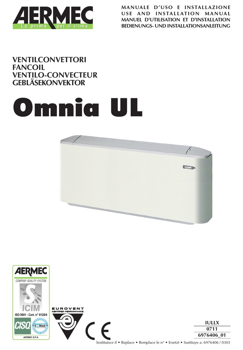
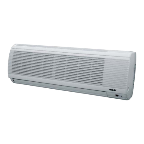
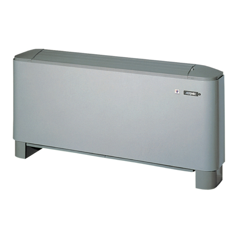
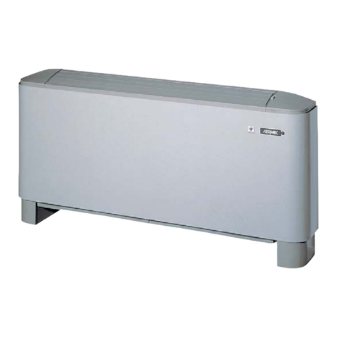
AERMEC OMNIA ULS Technical specifications

2011 - 5217100_04
www.aermec.com
MANUALE D’USO E INSTALLAZIONE
USE AND INSTALLATION MANUAL
MANUEL D'UTILISATION ET D'INSTALLATION
B E D I E N U N G S - U N D I N S T A L L A T I O N S A N L E I T U N G
MANUAL DE INSTRUCCIONES E INSTALACIÓN
IT EN FR DE ES
230V ~ 50Hz
OMNIA ULS
OMNIA ULS_C

Conservare i manuali in luogo asciutto, per evitare il
deterioramento, per almeno 10 anni per eventuali riferimenti futuri.
Leggere attentamente e completamente tutte le informazioni
contenute in questo manuale. Prestare particolarmente attenzione
alle norme d’uso accompagnate dalle scritte “PERICOLO” o
“ATTENZIONE” in quanto, se non osservate, possono causare danno
alla macchina e/o a persone e cose.
Per anomalie non contemplate da questo manuale, interpellare
tempestivamente il Servizio Assistenza di zona.
L'apparecchio deve essere installato in maniera tale da rendere
possibili operazioni di manutenzione e/o riparazione.
La garanzia dell'apparecchio non copre in ogni caso i costi dovuti
ad autoscale, ponteggi o altri sistemi di elevazione che si rendesero
necessari per effettuare gli interventi in garanzia.
AERMEC S.p.A. declina ogni responsabilità per qualsiasi danno dovuto ad
un uso improprio della macchina, ad una lettura parziale o superficiale
delle informazioni contenute in questo manuale.
OSSERVAZIONI
Store the manuals in a dry location to avoid deterioration,
as they must be kept for at least 10 years for any future reference.
All the information in this manual must be carefully read and
understood. Pay particular attention to the operating standards
with “DANGER” or “WARNING” signals as failure to comply with
them can cause damage to the machine and/or persons or objects.
If any malfunctions are not included in this manual, contact the local
After-sales Service immediately.
The apparatus must be installed in such a way that maintenance
and/or repair operations are possible.
The apparatus's warranty does not in any case cover costs due to
automatic ladders, scaffolding or other lifting systems necessary for
carrying out repairs under guarantee.
AERMEC S.p.A. declines all responsibility for any damage whatsoever
caused by improper use of the machine, and a partial or superficial
acquaintance with the information contained in this manual.
REMARKS
Conserver les manuels dans un endroit sec, afin d’éviter leur
détérioration, pendant au moins 10 ans, pour toutes éventuelles
consultations futures.
Lire attentivement et entièrement toutes les informations
contenues dans ce manuel. Prêter une attention particulière aux
normes d’utilisation signalées par les inscriptions “DANGER” ou
“ATTENTION”, car leur non observance pourrait causer un dommage
à l’appareil et/ou aux personnes et objets.
Pour toute anomalie non mentionnée dans ce manuel, contacter
aussitôt le service après-vente de votre secteur.
Lors de l'installation de l'appareil, il faut prévoir l'espace nécessaire
pour les opérations d'entretien et/ou de réparation.
La garantie de l'appareil ne couvre pas les coûts dérivant de l'utilisation
de voitures avec échelle mécanique, d'échafaudages ou d'autres
systèmes de levée employés pour effectuer des interventions en
garantie.
AERMEC S.p.A. décline toute responsabilité pour tout dommage dû
à une utilisation impropre de l’appareil et à une lecture partielle ou
superficielle des informations contenues dans ce manuel.
REMARQUES
Guarde los manuales en un lugar seco para evitar su deterioro, al menos
durante 10 años, por si fuera posible consultarlos en el futuro.
Leer atenta y completamente todas las informaciones contenidas
en este manual. Preste particular atención a las normas de uso
acompañadas de las indicaciones “PELIGRO” o “ATENCIÓN” puesto
que, si no se cumplen, pueden causar el deterioro de la máquina y/o
daños personales y materiales.
En caso de anomalías no contempladas en este manual, contacte
inmediatamente con el Servicio de Asistencia de su zona.
El aparato debe ser instalado de manera que haga posibles las
operaciones de mantenimiento y/o reparación.
En cualquier caso, la garantía del aparato no cubre los costes derivados
del uso de escaleras automáticas, andamios u otros sistemas de
elevación necesarios para efectuar las intervenciones en garantía.
AERMEC S.p.A. declina cualquier responsabilidad por cualquier daño
debido a un uso impropio de la máquina, o bien a una lectura parcial o
superficial de las informaciones contenidas en este manual.
OBSERVACIONES
Bewahren Sie die Gebrauchsanleitungen mindestens 10 Jahre für
eventuelles zukünftiges Nachschlagen an einem trockenen Ort auf.
Alle in diesem Handbuch enthaltenen Informationen
aufmerksam und vollständig lesen. Insbesondere auf die
Benutzungsanweisungen mit den Hinweisen "VORSICHT" oder
"ACHTUNG" achten, da deren Nichtbeachtung Schäden am Gerät
bzw. Sach- und Personenschäden zur Folge haben kann.
Bei Betriebsstörungen, die in dieser Gebrauchsanweisung nicht
aufgeführt sind, wenden Sie sich umgehend an die zuständige
Kundendienststelle.
Das Gerät so aufstellen, dass Instandhaltungs- und/oder
Reparaturarbeiten durchgeführt werden können.
Die Garantie des Gerätes deckt in keinem Fall Kosten für
Feuerwehrleitern, Gerüste oder andere Hebesysteme ab, die sich für die
Garantiearbeiten als erforderlich erweisen sollten.
Die AERMEC S.p.A. übernimmt keine Haftung für Schäden aus dem
unsachgemäßen Gebrauch des Gerätes und der teilweisen oder
oberflächlichen Lektüre der in diesem Handbuch enthaltenen
Informationen.
HINWEISE

Indice
Avvertenze generali ......................................................................................................................6
Informazioni importanti e manutenzione ...........................................................................8
Imballo................................................................................................................................................9
Manutenzione filtro (fig. 1 capitolo disegni )......................................................................9
Installazione dell’unità .................................................................................................................9
Collegamenti idraulici ..................................................................................................................9
Collegamenti elettrici ...................................................................................................................9
Index
General warnings ........................................................................................................................ 10
Product description.................................................................................................................... 12
Important information and maintenance......................................................................... 12
Packaging....................................................................................................................................... 13
Filter maintenance (fig.1 drawings chapter ) ................................................................... 13
Installation of the unit ............................................................................................................... 13
Hydraulic connections .............................................................................................................. 13
Electrical connections................................................................................................................ 13
Index
Avertissements généraux ........................................................................................................ 14
Description du produit.............................................................................................................. 16
Informations importantes et maintenance...................................................................... 16
Emballage....................................................................................................................................... 17
Entretien du filtre (fig. 1 chapitre dessins)......................................................................... 17
Installation de l'unite.................................................................................................................. 17
Raccordements hydrauliques................................................................................................. 17
Branchements électriques....................................................................................................... 17
Index
Allgemeine hinweise.................................................................................................................. 18
Beschreibung des produkts.................................................................................................... 20
Wichtige hinweise und wartung........................................................................................... 20
Verpackung.................................................................................................................................... 21
Wartung des filters (abb. 1 kapitel zeichnungen ) ......................................................... 21
Installation der einheit .............................................................................................................. 21
Wasseranschlüsse........................................................................................................................ 21
Elektrische anschlüsse............................................................................................................... 21
Indice
Descripción del producto ........................................................................................................ 24
Informaciones importantes y mantenimiento................................................................ 24
Embalaje ......................................................................................................................................... 25
Mantenimiento del filtro (fig. 1 capítulo dibujos) .......................................................... 25
Instalación de la unidad............................................................................................................ 25
Conexiones hidráulicas............................................................................................................. 25
Conexiones eléctricas................................................................................................................ 25
Limiti di funzionamento - operating limits - limites de fonctionnement betriebs-
grenzen - límites de funcionamiento.................................................................................. 26
Disegni - drawings - dessins - zeichnungen - dibujos.................................................. 29
Installazione del pannello comandi (accessorio) - installation of the control panel
(accessory) - installation du tableau de commande (accessoire) - installation der
zentrale (zubehör) - instalación del panel de control (accesorio)............................ 30
Spazi tecnici minimi - minimum technical spaces - espaces techniques minimum
technische mindestabstände - espacios técnicos mínimos [mm].......................... 30
Dati dimensionali • dimensions • dimensions • abmessungen • dimensiones [mm] ...
............................................................................................................................................................. 31
schemi elettrici • wiring diagrams • schemas electriques • schaltpläne • esquemas
eléctricos......................................................................................................................................... 33

IT EN FR DE ES
4UL_S 2011 - 5217100_04
TRASPORTO • TRANSPORT • TRANSPORT • TRANSPORT • TRANSPORTE
NON bagnare. Tenere
al riparo dalla pioggia.
KEEP DRY. Keep out of
the rain.
NE PAS mouiller. Tenir à
l’abri de la pluie.
NICHT nass machen.
Vor Regen geschützt
anbringen
NO mojar. Conservar
protegido de la lluvia.
NON calpestare. DO NOT step on unit. NE PAS marcher
sur l’appareil. NICHT betreten . NO pisar.
N
Sovrapponibilità:
controllare sull’imballo
per conoscere il
numero di macchine
impilabili.
Stackability: check the
package to know the
number of stackable
machines.
Empilement : vérifier
sur l’emballage le
nombre
d’appareils empilables.
Stapelbarkeit: Auf
der Verpackung
nachsehen, wie die
Anzahl der stapelbaren
Geräte lautet.
Superponibilidad:
observar en el
embalaje la cantidad
de máquinas que
pueden apilarse.
>25Kg
NON trasportare la
macchina da soli se il
suo peso supera i 25Kg.
DO NOT carry the
equipment alone if
weight exceeds 25Kg.
NE PAS faire transporter
l’appareil par une seule
personne si son poids
est supérieur à 25kg.
NICHT das Gerät allein
transportieren, wenn
sein Gewicht die 25kg
übersteigt.
NO transportar la
máquina solos si su
peso es superior a los
25Kg.
NON lasciare gli imballi
sciolti durante il
trasporto.
Non rovesciare.
DO NOT leave boxes
unsecured during
transportation.
Do not overturn.
NE PAS laisser les
emballages sans
attaches durant le
transport.
Ne pas renverser.
NICHT die
Verpackungen
während des
Transports geöffnet
lassen.
Nicht stürzen.
NO dejar los embalajes
sin sujetar durante el
transporte.
No invertir.
Fragile, maneggiare
con cura.
Fragile, handle with
care.
Fragile, manipuler avec
soin.
Zerbrechlich, sorgfältig
handhaben.
Frágil, manipular con
cuidado.
SIMBOLI DI SICUREZZA • SAFETY SYMBOL • SIMBOIES DE SECURITE • SICHERHEITSSYMBOLEOLE •
SÍMBOLOS DE SEGURIDAD
Pericolo:
Tensione
Danger:
Power supply
Danger:
Tension
Gefahr !
Spannung
Peligro:
Tensión
Pericolo:
Organi in movimento
Danger:
Movings parts
Danger:
Organes en
mouvement
Gefahr !
Rotierende Teile
Peligro:
Elementos en
movimiento
Pericolo!!! Danger!!! Danger!!! Gefahr!!! Peligro!!!
Imballo: indicazioni per
trasporto e stoccaggio
Packing: indications for
transport and storage
Emballage: indications
pour le transport et le
stockage
Verpackung:
Anweisungen für
Transport und
Lagerung
Embalaje: indicaciones
para el transporte y el
almacenamiento

IT EN FR DE ES
5UL_S 2011 - 5217100_04
IDENTIFICAZIONE DEL PRODOTTO PRODUCT IDENTIFICATION IDENTIFICATION DU PRODUIT
KENNZEICHNUNG DES PRODUKTES IDENTIFICACIÓN DEL PRODUCTO
IT
I ventilconvettori sono identificabili attraverso:
ETICHETTA IMBALLO
Posta sull’imballo, riporta i dati identificativi del prodotto.
TARGHETTA TECNICA
Posta all’interno dell’unità, riporta i dati identificativi e tecnici del prodotto.
ATTENZIONE: La manomissione, l’asportazione, la mancanza della targhetta di identificazione o quant’altro non permetta la sicura
identificazione del prodotto, rende difficoltosa qualsiasi operazione di installazione e manutenzione.
EN
The fan coils can be identified through:
PACKAGING LABEL
Located on the packaging, it indicates the product identification data.
TECHNICAL PLATE
Located inside the unit, it indicates the identification and technical data of the product.
ATTENTION: Tampering, removal, the lack of the identification plate does not allow the product to be safely identified and will
complicate any installation or maintenance operations.
FR
Les ventilo-convecteurs peuvent être identifiés par :
L’ÉTIQUETTE D’EMBALLAGE
Elle se trouve sur l’emballage et reporte les données d’identification du produit.
LA PLAQUE TECHNIQUE
Elle se trouve à l’intérieur de l’unité et reporte les données d’identification et les caractéristiques techniques du produit.
ATTENTION : L’altération, l’enlèvement, l’absence de la plaque d’identification ou de tout autre élément ne permettant pas d’identifier clairement
le produit, complique toute opération d’installation et de maintenance.
DE
Die Gebläsekonvektoren sind gekennzeichnet durch:
VERPACKUNGSETIKETT Auf der Verpackung angebracht, enthält die Kenndaten des Produktes.
TYPENSCHILD Im Inneren der Einheit angebracht, enthält die Kenndaten und die technischen Merkmale des Produktes.
ACHTUNG: Die Veränderung, das Entfernen oder das Fehlen des Typenschildes oder anderer Elemente, welche die sichere Identifizierung
des Produktes ermöglichen, erschweren die Installations- und Wartungsarbeiten.
ES
Los ventiloconvectores se pueden identificar a través de:
ETIQUETA DE EMBALAJE
Colocada en el embalaje, muestra los datos de identificación del producto.
PLACA TÉCNICA
Colocada dentro de la unidad, muestra los datos de identificación y técnicos del producto.
ATENCIÓN: La alteración, extracción, falta de la placa de identificación técnica o todo lo que no permita la identificación segura del
producto, vuelve dificultosa cualquier operación de instalación y mantenimiento.
Volt
ETICHETTA IMBALLO - PRODUCT IDENTIFICATION
L’ÉTIQUETTE D’EMBALLAGE -VERPACKUNGSETIKETT ETIQUETA DE
EMBALAJE
TARGHETTA TECNICA - PACKAGING LABEL - LA PLAQUE
TECHNIQUE - TYPENSCHILD - PLACA TÉCNICA

IT EN FR DE ES
6UL_S 2011 - 5217100_04
AVVERTENZE GENERALI
AVVERTENZE SULLA SICUREZZA E NORME D'INSTALLAZIONE
• Vengono qui riportate le indicazioni essenziali per una corretta
installazione delle apparecchiature. Si lascia comunque
all’esperienza dell’installatore il perfezionamento di tutte le
operazioni a seconda delle esigenze speciche.
• Non modicare o manomettere le unità in quanto si possono creare
situazioni di pericolo ed il costruttore non sarà responsabile di
eventuali danni provocati. La validità della garanzia decade nel caso
non siano rispettate le indicazioni menzionate in questo manuale.
• Prima di iniziare qualsiasi lavoro è necessario LEGGERE
ATTENTAMENTE LE ISTRUZIONI E FARE DEI CONTROLLI DI SICUREZZA
PER EVITARE QUALSIASI PERICOLO.
• Tutto il personale addetto deve essere a conoscenza delle operazioni
e dei pericoli che possono insorgere nel momento in cui si iniziano
tutte le operazioni di installazione dell'unità.
• L’unità deve essere installata in posizione tale da consentire
facilmente la manutenzione ordinaria (pulizia del ltro) e
straordinaria.
ATTENZIONE: il ventilconvettore è collegato alla rete elettrica ed al
circuito idraulico, un intervento da parte di personale non provvisto di
specica competenza tecnica può causare danni allo stesso operatore,
all’apparecchio ed all’ambiente circostante.
ATTENZIONE: L'apparecchio deve essere installato conformemente
alle regole impiantistiche nazionali.
ATTENZIONE: prima di eettuare qualsiasi intervento, assicurarsi che
l’alimentazione elettrica sia disinserita.
ATTENZIONE: Installare un dispositivo, interruttore generale o spina
elettrica che consenta di interrompere completamente l'alimentazione
elettrica dall'apparecchio.
ATTENZIONE: Per proteggere l’unità contro i cortocircuiti, montare
sulla linea di alimentazione un interruttore onnipolare magnetotermico. Al
ne di evitare ogni pericolo dovuto al riarmo accidentale del dispositivo
termico di interruzione, questo apparecchio non deve essere alimentato
con un dispositivo di manovra esterno, quale un temporizzatore, oppure
essere connesso a un circuito che viene regolarmente alimentato o
disalimentato dal servizio.
ATTENZIONE! PERICOLO! È vietato qualsiasi uso del dispositivo al di
fuori di quanto espressamente indicato da Aermec.
ALIMENTARE IL VENTILCONVETTORE SOLO CON LA TENSIONE
INDICATA NELLA TARGHETTA
Utilizzando alimentazioni elettriche diverse il ventilconvettore può subire
danni irreparabili.
ANOMALIE DI FUNZIONAMENTO
In caso di funzionamento anomalo, togliere tensione all’unità, poi ridare
tensione e procedere ad un riavvio dell’apparecchio.
Non tentare di riparare l'unità da soli, è molto pericoloso!
Se il problema si ripresenta, chiamare tempestivamente il Servizio
Assistenza di zona.
NON STRATTONARE IL CAVO ELETTRICO
È molto pericoloso tirare, calpestare, schiacciare o ssare con chiodi o
puntine il cavo elettrico di alimentazione.
Il cavo danneggiato può provocare corti circuiti e danni alle persone.
CAVO DI ALIMENTAZIONE ELETTRICA
Se il cavo di alimentazione è danneggiato, esso deve essere sostituito
con un cavo nuovo di sezione adeguata. Far eseguire la riparazione
da “Personale provvisto di specica competenza tecnica”, in modo da
prevenire ogni rischio.
Non riparare i cavi rovinati.
Per l’alimentazione elettrica usare cavi integri e con sezione adeguata al
carico.
NON INFILARE OGGETTI SULL’USCITA DELL’ARIA
Non inserire oggetti di nessun tipo nelle feritoie di uscita dell’aria.
Ciò potrebbe provocare ferimenti alla persona e danni al ventilatore.
• Le unità Omnia ULSsono costruite secondo gli standard tecnici
e le regole di sicurezza riconosciute. Sono progettate per il
riscaldamento e il rarescamento dell’aria ambiente, e dovranno
essere destinate a questo uso compatibilmente con le loro
caratteristiche prestazionali.
• È esclusa qualsiasi responsabilità contrattuale ed extracontrattuale
dell’Azienda per danni causati a persone, animali o cose, da errori di
installazione, di regolazione e di manutenzione o da usi impropri.
Tutti gli usi non espressamente indicati in questo manuale non sono
consentiti.
• Durante le fasi di installazione, manutenzione e pulizia, dotarsi di
adeguati Dispositivi di Protezione Individuale (DPI).
• L’unità non deve essere usata come ricovero di attrezzature, parti
di ricambio. Qualsiasi altro utilizzo dierente da quello esposto nel
presente manuale può generare pericoli ed è pertanto vietato.
• ATTENZIONE: i collegamenti elettrici, i collegamenti idraulici,
l’installazione dei ventilconvettori e dei loro accessori devono
essere eseguiti solo da soggetti in possesso dei requisiti tecnico-
professionali di abilitazione all’installazione, alla trasformazione,
all’ampliamento e alla manutenzione degli impianti ed in grado
di vericare gli stessi ai ni della sicurezza e della funzionalità
(in ottemperanza alla legislazione nazionale vigente nel paese
di destinazione), in questo sto manuale saranno identicati
anche come: tecnico abilitato e qualificato provvisto di specifica
competenza tecnica.
• AERMEC non si assume nessuna responsabilità per danni
insorti a causa della mancata osservanza di queste istruzioni.
• Prima dell’installazione controllare che l’unità non abbia subito danni
durante la fase di trasporto:
• l’utilizzo dell'unità danneggiata potrebbe risultare pericolosa;
• il piano d’appoggio deve essere in grado di sostenere il peso dell’unità.
Nota:
Per ogni futuro riferimento e per ogni comunicazione con AERMEC
S.p.A. è necessario indicare il numero di matricola.
CONSERVAZIONE DELLA DOCUMENTAZIONE
• Consegnare le istruzioni con tutta la documentazione complementare
all'utilizzatore dell'unità che si assumerà la responsabilità per la
conservazione delle istruzioni anché esse siano sempre a disposizione
in caso di necessità.
TRASPORTO
• Per trasportare l’unità in sicurezza riferirsi alle indicazioni del peso
presenti nella targhetta.
• In ogni caso il trasporto deve avvenire con le seguenti precauzioni:
• l’unità e gli eventuali accessori non devono essere sottoposti ad urti
violenti per non pregiudicare l’integrità della struttura e dei componenti
interni;
• l’unità e gli eventuali accessori, durante il trasporto, devono essere
protetti in modo che non possano subire urti, per questo devono essere
adeguatamente bloccati sul piano di trasporto mediante funi o qualsiasi
altro mezzo che ne impedisca il movimento;
• l’unità e gli eventuali accessori, durante il trasporto e lo stoccaggio,
devono essere sempre protetti dalle intemperie.
A B C
VERIFICHE AL RICEVIMENTO
• Al ricevimento dell’unità è necessario eseguire un primo controllo visivo
per vericare:
• la corretta corrispondenza dell’ordine con quanto riportato nei
documenti di trasporto;
• l’integrità dell’imballo;
• l’integrità dell’unità;
• la presenza di tutti i componenti.
• Nel caso venissero riscontrati danni o mancati componenti è necessario
segnalarli sui documenti di trasporto.
IT EN FR DE ES
7UL_S 2011 - 5217100_04
MOVIMENTAZIONE
• ATTENZIONE! : Durante le fase di movimentazione dotarsi di adeguati
dispositivi di protezione individuale (DPI).
• Prima dell’installazione e dell’uso si raccomanda di togliere
completamente l’imballaggio dall’unità base e da tutti i componenti
forniti a corredo.
INSTALLAZIONE
• Leggere attentamente il presente fascicolo; l’esecuzione di tutti i lavori
deve essere eettuata da un tecnico abilitato e qualicato provvisto di
specica competenza tecnica, secondo le norme vigenti in materia nel
paese di installazione.
• Per l’installazione si consiglia di seguire attentamente le indicazioni fornite
nei paragra successivi. I paragra sono organizzati cronologicamente in
modo da agevolare ogni fase dell’installazione.
• Recuperare all’interno dell’unità i documenti (manuali e dichiarazione di
conformità) ed i componenti necessari per completare l’installazione.
• Gli accessori Aermec sono forniti completi di manuali per l'installazione
e l'uso.
• Gli accessori Aermec sono progettati per integrarsi con le unità Aermec
sia per l'aspetto funzionale che per la sicurezza. Le nostre unità sono
progettate per poter montare all'interno gli accessori riscaldatori
supplementari Aermec e se correttamente montati non hanno alcun
inusso sull'ambiente circostante, gli spazi tecnici sono invariati rispetto
all'unità base.
Prima di eseguire l’installazione devono essere vericati gli spazi
tecnici necessari:
• all’operatore per compiere l’installazione;
• al collegamento ai circuiti idraulici ed alle eventuali valvole;
• al collegamento dell'alimentazione elettrica;
• ilcollegamentodi un pannelloalo esterno all'unità(quandosiaprevisto);
• alla predisposizione dei canali di mandata e di aspirazione (per i modelli
che lo prevedono);
• al corretto e suciente usso dell'aria sia in aspirazione che in mandata,
• allo scarico della condensa;
• alla pulizia dei ltri;
• alla pulizia dei componenti interni e alla manutenzione.
AVVERTENZE SULL'USO
ATTENZIONE: L’apparecchio può essere utilizzato da bambini di età
non inferiore a 8 anni e da persone con ridotte capacità siche, sensoriali
o mentali, o prive di esperienza o della necessaria conoscenza, purché
sotto sorveglianza oppure dopo che le stesse abbiano ricevuto istruzioni
relative all’uso sicuro. Dell’apparecchio e alla comprensione dei pericoli ad
esso inerenti. I bambini non devono giocare con l’apparecchio. La pulizia e
la manutenzione destinata ad essere eettuata dall’utilizzatore non deve
essere eettuata da bambini senza sorveglianza.
NON USARE IL VENTILCONVETTORE IN MODO IMPROPRIO
Il ventilconvettore non va utilizzato per allevare, far nascere e crescere
animali.
VENTILARE L'AMBIENTE
Si consiglia di ventilare periodicamente l'ambiente ove è installato il
ventilconvettore, specialmente se nel locale risiedono parecchie persone
o se sono presenti apparecchiature a gas o sorgenti di odori.
REGOLARE CORRETTAMENTE LA TEMPERATURA
La temperatura ambiente va regolata in modo da consentire il massimo
benessere alle persone presenti, specialmente se si tratta di anziani,
bambini o ammalati, evitando sbalzi di temperatura tra interno ed
esterno superiori a 7°C in estate. In estate una temperatura troppo bassa
comporta maggiori consumi elettrici.
ORIENTARE CORRETTAMENTE IL GETTO D'ARIA
L'aria che esce dal ventilconvettore non deve investire direttamente le
persone; infatti, anche se a temperatura maggiore di quella dell'ambiente,
può provocare sensazione di freddo e conseguente disagio.
DURANTE IL FUNZIONAMENTO
• Durante il funzionamento lasciare sempre il ltro montato sul
ventilconvettore altrimenti la polvere presente nell'aria andrà a sporcare
le superci della batteria.
È NORMALE
• Nel funzionamento in rareddamento può uscire del vapore acqueo
dalla mandata del ventilconvettore.
• Nel funzionamento in riscaldamento un leggero fruscio d’aria può essere
avvertibile in prossimità del ventilconvettore. Talvolta il ventilconvettore
può emettere odori sgradevoli dovuti all'accumulo di sostanze presenti
nell'aria dell'ambiente (specialmente se non si provvede a ventilare
periodicamente la stanza, pulire il ltro più spesso).
• Durante il funzionamento si potrebbero avvertire rumori e scricchiolii
interni all'apparecchio dovuti alle diverse dilatazioni termiche
degli elementi (plastici e metallici), ciò comunque non indica un
malfunzionamento e non provoca danni all’unità se si rispettano le
temperature dell'acqua di ingresso indicate nei limiti di funzionamento.
GARANZIA DI 3 ANNI
La garanzia è valida solo se l’apparecchio è venduto ed installato sul territorio italiano. Il periodo decorre dalla data d’acquisto comprovata da un
documento che abbia validità fiscale (fattura o ricevuta) e che riporti la sigla commerciale dell’apparecchio. Il documento dovrà essere esibito, al
momento dell’intervento, al tecnico del Servizio Assistenza Aermec di zona.
Il diritto alla garanzia decade in caso di:
– interventi di riparazione effettuati sull’apparecchiatura da tecnici non autorizzati;
– guasti conseguenti ad azioni volontarie o accidentali che non derivino da difetti originari dei materiali di fabbricazione.
AERMEC Spa effettuerà la riparazione o la sostituzione gratuita, a sua scelta, delle parti di apparecchiatura che dovessero presentare difetti
dei materiali o di fabbricazione tali da impedirne il normale funzionamento. Gli eventuali interventi di riparazione o sostituzione di parti
dell’apparecchio, non modificano la data di decorrenza e la durata del periodo di garanzia. Le parti difettose sostituite resteranno di proprietà della
AERMEC Spa.
Non è prevista in alcun caso la sostituzione dell’apparecchio. La garanzia non copre le parti dell’apparecchio che risultassero difettose a causa del
mancato rispetto delle istruzioni d’uso, di un’errata installazione o manutenzione, di danneggiamenti dovuti al trasporto, di difetti dell’impianto
(es: scarichi di condensa non efficienti).Non sono coperte, infine, le normali operazioni di manutenzione periodica (es: la pulizia dei filtri d’aria) e la
sostituzione delle parti di normale consumo (es: i filtri d’aria).
Le agenzie di Vendita Aermec ed i Servizi di Assistenza Tecnica Aermec della vostra provincia sono negli Elenchi telefonici dei capoluoghi
di provincia - vedi“Aermec” - e nelle Pagine Gialle alla voce“Condizionatori d’aria - Commercio”.

IT EN FR DE ES
8UL_S 2011 - 5217100_04
DESCRIZIONE DEL PRODOTTO
ATTENZIONE: il ventilconvettore è collegato alla rete elettrica ed al
circuito idraulico, un intervento da parte di personale non provvisto di
specifica competenza tecnica può causare danni allo stesso operatore,
all’apparecchio ed all’ambiente circostante.
ALIMENTARE IL VENTILCONVETTORE SOLO CON TENSIONE 230
VOLT MONOFASE
• Utilizzando alimentazioni elettriche diverse il ventilconvettore
può subire danni irreparabili.
NON USARE ILVENTILCONVETTORE IN MODO IMPROPRIO
• Il ventilconvettore non va utilizzato per allevare, far nascere e
crescere animali.
VENTILARE L'AMBIENTE
• Si consiglia di ventilare periodicamente l'ambiente ove è installato
il ventilconvettore, specialmente se nel locale risiedono parecchie
persone o se sono presenti apparecchiature a gas o sorgenti di
odori.
REGOLARE CORRETTAMENTE LA TEMPERATURA
• La temperatura ambiente va regolata in modo da consentire il
massimo benessere alle persone presenti, specialmente se si tratta
di anziani, bambini o ammalati, evitando sbalzi di temperatura tra
interno ed esterno superiori a 7 °C in estate.
• In estate una temperatura troppo bassa comporta maggiori
consumi elettrici.
ORIENTARE CORRETTAMENTE IL GETTO D'ARIA
• L'aria che esce dal ventilconvettore non deve investire
direttamente le persone; infatti, anche se a temperatura maggiore
di quella dell'ambiente, può provocare sensazione di freddo e
conseguente disagio.
NON USARE ACQUA TROPPO CALDA
• Per pulire il ventilconvettore usare panni o spugne morbidi
bagnati in acqua al massimo a 40 °C. Non usare prodotti chimici
o solventi per nessuna parte del ventilconvettore. Non spruzzare
acqua sulle superci esterne o interne del ventilconvettore (si
potrebbero provocare dei corti circuiti).
PULIRE PERIODICAMENTE IL FILTRO FIG. 1 CAPITOLO DISEGNI
• Una pulizia frequente del ltro garantisce una maggiore ecienza
di funzionamento.
• Controllare se il ltro risulta molto sporco: nel caso ripetere
l’operazione più spesso.
• Pulire frequentemente, togliere la polvere accumulata con un
aspiratore.
• Quando il ltro è pulito rimontarlo sul ventilconvettore
procedendo al contrario rispetto allo smontaggio.
DURANTE IL FUNZIONAMENTO
• Lasciare sempre il ltro montato sul ventilconvettore durante il
funzionamento, altrimenti la polvere presente nell'aria andrà a
sporcare le superci della batteria.
È NORMALE
• Nel funzionamento in rareddamento può uscire del vapore
acqueo dalla mandata del ventilconvettore.
• Nel funzionamento in riscaldamento un leggero fruscio d’aria
può essere avvertibile in prossimità del ventilconvettore.
Talvolta il ventilconvettore può emettere odori sgradevoli
dovuti all'accumulo di sostanze presenti nell'aria dell'ambiente
(specialmente se non si provvede a ventilare periodicamente la
stanza, pulire il ltro più spesso).
• Durante il funzionamento si potrebbero avvertire rumori e
scricchiolii interni all'apparecchio dovuti alle diverse dilatazioni
termiche degli elementi (plastici e metallici), ciò comunque non
indica un malfunzionamento e non provoca danni all’unità se non
si supera la massima temperatura dell'acqua di ingresso.
ATTENZIONE
• Si eviti che l'apparecchio sia utilizzato da bambini o persone inabili
senza opportuna sorveglianza; si ricorda inoltre che l'apparecchio
non deve essere usato dai bambini come gioco.
INFORMAZIONI IMPORTANTI E MANUTENZIONE
ATTENZIONE
Tutte le informazioni riguardanti gli schemi elettrici, l'installazione e l'utilizzo degli accessori e dei termostati compatibili
sono contenute nelle istruzioni a corredo con l'accessorio scelto.
Per ulteriori informazioni contattare Aermec.
• I ventilconvettori Omnia ULS sono stati progettati per poter
rispondere all’esigenza, negli ambienti soprattutto residenziali,
di coniugare le caratteristiche tipiche del radiatore, ridotta
profondità e silenziosità di funzionamento con la peculiarità del
ventilconvettore di poter climatizzare gli ambienti tutto l’anno.
• Sono installabili in qualsiasi tipo d'impianto a 2 tubi e in
abbinamento a qualsiasi generatore di calore anche a basse
temperature e grazie alla disponibilità di varie versioni e
congurazioni, è facile scegliere la soluzione ottimale per qualsiasi
esigenza.
• Struttura in lamiera zincata da 12/10 e 10/10 mm.
• Mantello frontale in lamiera zincata da 10/10 mm con verniciatura
in polvere epossidica bianca RAL9003 e con isolante termo-
acustico da 15 mm di spessore.
• Questi ventilconvettori possiedono, una ventilazione
estremamente silenziosa, grazie all’adozione di speciali ventilatori
tangenziali, che li pone ai vertici del comfort acustico.
• Il motore elettrico è monofase a tre velocità, con condensatore
permanentemente inserito.
• Con tubi di rame ed alette in alluminio, la batteria principale ha
attacchi idraulici gas femmina a sinistra e i collettori sono corredati
di sfoghi d'aria.
• Lo scambiatore non è adatto ad essere utilizzato in atmosfere
corrosive o in tutti quegli ambienti in cui si possano generare
corrosioni nei confronti dell'alluminio.
• La batteria ha gli attacchi idraulici a sinistra e non è reversibile.
• Con regolazione termostatica, commutazione manuale o senza
regolazione per abbinamento ccon i comandi TXBS, T-TOUCH-S e
VMF-E2S. Nel caso si utilizzi il VMF-E2S è necessario montare uno
tra i termostatiVMF-E0X eVMF-E19, i quali vanno installati a bordo
macchina tramite la staa del KITSV.
VERSIONI:
• ULSxx: motore a 3 velocità ed è senza comando;
• ULSxxC: motore a 3 velocità e comando installato a bordo
ULS ULS_C

IT EN FR DE ES
9UL_S 2011 - 5217100_04
• I ventilconvettori vengono spediti con imballo standard costituito
da gusci di polistirolo espanso e cartone.
IMBALLO
ATTENZIONE: prima di effettuare qualsiasi intervento, assicurarsi
che l’alimentazione elettrica sia disinserita.
ATTENZIONE: i collegamenti elettrici, l’installazione dei
ventilconvettori e dei loro accessori devono essere eseguiti solo
da soggetti in possesso dei requisiti tecnico-professionali di
abilitazione all’installazione, alla trasformazione, all’ampliamento
e alla manutenzione degli impianti ed in grado di verificare gli stessi
ai fini della sicurezza e della funzionalità.
Il ventilconvettore deve essere installato in posizione tale da consentire
facilmente la manutenzione ordinaria (pulizia del filtro) e straordinaria,
nonchè l’accesso alla valvola di sfiato dell’aria sulla fiancata del telaio (lato
attacchi).
Il luogo di montaggio deve essere scelto in modo che il limite di
temperatura ambiente massimo e minimo venga rispettato 0÷45°C (<85%
U.R.).
Per installare l’unità procedere come segue:
- Nella installazione a parete si mantenga una distanza minima dal
pavimento di 80 mm. In caso di installazione a pavimento per mezzo
dei piedini estetici, si faccia riferimento alle istruzioni a corredo
dell’accessorio.
- Rimuovere le fiancate dell'unità attraverso le viti di fissaggio dedicate
(fig. 2 capitolo Disegni )
- Per il fissaggio al muro pensile usare dei tasselli ad espansione .
- Effettuare i collegamenti idraulici (fig. 3 capitolo Disegni ).
La posizione e il diametro degli attacchi idraulici sono riportati nei dati
dimensionali.
Si consiglia di isolare adeguatamente le tubazioni dell’acqua
o di installare l’apposita bacinella ausiliaria di raccolta condensa,
disponibile come accessorio, per evitare gocciolamenti durante il
funzionamento in raffreddamento.
In caso di installazione orizzontale, montare il raccordo
di scarico della condensa fornito a corredo. Si abbia cura
di sigillare con silicone la connessione tra bacinella e
raccordo.La rete di scarico della condensa deve essere
opportunamente dimensionata e le tubazioni posizionate in modo
da mantenere lungo il percorso un’adeguata pendenza (min.1%). Nel
caso di scarico nella rete fognaria, si consiglia di realizzare un sifone
che impedisca la risalita di cattivi odori verso gli ambienti.
- Effettuare i collegamenti elettrici secondo quanto riportato negli
schemi elettrici. (vedi pag.34).
- Per accedere al filtro e necessario piegare leggermente i dentini in
plastica presenti sulla testata dell'unità.
- Rimuovere la testata per accedere al vano di alloggiamaneto del filtro
- Rimuovere il filtro per eventuali manutenzioni.
ATTENZIONE: prima di effettuare qualsiasi intervento, assicurarsi
che l’alimentazione elettrica sia disinserita.
ATTENZIONE: i collegamenti elettrici, l’installazione dei
ventilconvettori e dei loro accessori devono essere eseguiti solo
da soggetti in possesso dei requisiti tecnico-professionali di
abilitazione all’installazione, alla trasformazione, all’ampliamento
e alla manutenzione degli impianti ed in grado di verificare gli
stessi ai fini della sicurezza e della funzionalità.
CARATTERISTICHE DEI CAVI DI COLLEGAMENTO
Usare cavi tipo H05V-K oppure N07V-K con isolamento 300/500 V
incassati in tubo o canalina.
Tutti i cavi devono essere incassati in tubo o canalina finchè non sono
all’interno del ventilconvettore.
I cavi all’uscita dal tubo o canalina devono essere posizionati in modo
da non subire sollecitazioni a trazione o torsione e comunque protetti
da agenti esterni.
Cavi a trefolo possono essere usati solo con capicorda. Assicurarsi
che i trefoli dei fili siano ben inseriti.
Per tutti i collegamenti seguire gli schemi elettrici a corredo
dell’apparecchio e riportati sulla presente documentazione.
Gli schemi elettrici sono soggetti ad un continuo aggiornamento, è
obbligatorio quindi fare riferimento a quelli a bordo macchina.
Per proteggere l’unità contro i cortocircuiti, montare sulla linea di
alimentazione un interruttore onnipolare magnetotermico 2A 250V
(IG) con distanza minima di apertura dei contatti di 3mm.
INSTALLAZIONE DELL’UNITÀ
COLLEGAMENTI IDRAULICI
MANUTENZIONE FILTRO FIG. 1 CAPITOLO DISEGNI
COLLEGAMENTI ELETTRICI
E’ necessario che le condutture dell’acqua, dello scarico condensa e il
circuito elettrico siano già stati previsti.
La scelta ed il dimensionamento delle linee idrauliche è demandato per
competenza al progettista, che dovrà operare secondo le regole della
buona tecnica e della legislazione vigente.
Utilizzare sempre chiave e controchiave per fissare le tubazioni.
Si consiglia di isolare adeguatamente le tubazioni dell’acqua, per evitare
gocciolamenti durante il funzionamento in raffreddamento.
Eseguire il collaudo della tenuta dei collegamenti idraulici.

IT EN FR DE ES
10 UL_S 2011 - 5217100_04
GENERAL WARNINGS
• WARNINGS REGARDING SAFETY AND INSTALLATION
STANDARDS
• Follow the indications below to install the equipment correctly.
The completion of all operations, according to specic
requirements, is left to the experience of the installer.
• Do not modify or tamper with the units, as dangerous situations
can occur. The manufacturer will not be liable for any damage
caused. The validity of the warranty shall be void in the event of
failure to comply with the indications mentioned in this manual.
• Before starting any operations, READ THESE INSTRUCTIONS
CAREFULLY AND CARRY OUTTHE SAFETY CHECKS TO AVOID ALL
RISKS.
• All the sta involved must have thorough knowledge of the
operations and any danger that may arise when the installation
operations are carried out.
• The unit must be installed to facilitate routine (lter cleaning) and
special maintenance operations.
• ATTENTION: the fan coil is connected to the power supply
and the hydraulic circuit. Operations performed by persons who
do not have the required technical skills can lead to personal
injury to the operator or damage the unit and the surrounding
environment.
• ATTENTION: The unit must be installed in compliance with
national regulations.
• ATTENTION: make sure that the power supply has been
disconnected before carrying out any interventions.
• ATTENTION: Install a device, master switch or electric plug that
allows the unit’s power supply to be completely disconnected.
• ATTENTION: In order to protect the unit against short circuits,
mount a magnet circuit breaker omnipolar switch on the power
supply line. In order to avoid any danger due to the accidental
rearming of the thermal cut-out device, this appliance must
not be powered with an external switching device, such as a
timer, or be connected to a circuit that is regularly powered or
disconnected from the service.
• ATTENTION! DANGER! Any use other than what is indicated
by Aermec is prohibited.
• Supply the fan coil only with the voltage value indicated in
the data plate
• The fan coil may be permanently damaged if a dierent electric
power supply is used.
• OPERATION ANOMALIES
• In the event of operation anomalies, power o the unit and then
power it back on and re-start the unit.
• Do not try to repair the unit on your own, as it may be very
dangerous!
• If the problem persists, call the Area After-sales Service
immediately.
• Do not pull the electric cable
• It is very dangerous to pull, step on or crush the power supply
cable or secure it using nails or staples.
• The damaged cable can cause short circuits and injury to persons.
• Electric power supply cable
• If the power supply cable is damaged, it must be replaced with
a new cable of adequate section. Have the repair made by
"Qualied personnel", in order to prevent any risk.
• Do not repair damaged cables.
• For the electric power supply, use integral cables with suitable
section for the load.
• Do not introduce objects into air vents
• Do not introduce any objects into the air outlet slots.
• This could cause injury to persons or damage the fan.
•
INFORMATION
• The Omnia ULSAERMEC units are constructed according to the
recognised technical standards and safety regulations. They
have been designed and must be used for air conditioning and
heating purposes, in accordance with their technical features.
• Any contractual or extra-contractual liability of the Company is
excluded for injury/damage to persons, animals or objects owing
to installation, regulation and maintenance errors or improper
use. All uses not expressly indicated in this manual are prohibited.
• Use suitable Personal Protective Equipment (PPE) during
installation, maintenance, and cleaning stages.
• Do not use the unit as storage for equipment or spare parts. Any
use other than that indicated in this manual is prohibited as it can
generate dangerous situations.
• ATTENTION: the electric and hydraulic connections, together
with installation of the fan coils and their accessories must
only be performed by technicians who have the technical-
professional requisites for installation, transformation, extension
and maintenance of the systems and who can verify these
functions in terms of safety and functionality (in accordance with
the national laws in force in the country of installation). In this
manual they will be also identied as: experienced and qualied
technician with specic technical knowledge.
• Aermec will not be liable for damage due to failure to follow these
instructions.
• Make sure the unit has not been damaged during transport
before installation.
• using a damaged machine could be dangerous.
• the support surface must withstand the weight of the unit.
• Note:
• Always indicate the serial number for future reference
and for any communication with AERMEC S.p.A.
• STORING THE DOCUMENTATION
• Handovertheinstructions withalltherelateddocumentation
to the system user, who must store the instructions so that
they are always available in case of necessity.
TRANSPORT
• Refer to the weight indications on the data plate to transport the
unit safely.
• Take the following measures during transport:
• The unit and the accessories must not undergo violent impacts in
order not to aect the integrity of the structure and of the internal
components;
• during transportation, the unit and any accessories must be
protected in order to prevent impacts, for this reason they must
be properly secured on the transportation oor with ropes or any
other means that prevent their movement;
• during transport and storage, the unit and the accessories must
always be protected against bad weather.
A B C
VERIFICATIONS UPON RECEPTION
• Visually check the unit upon reception to make sure that:
• the order corresponds with what is indicated in the transport
documents;
• packaging is intact;
• the unit is intact;
• all the components have been provided.
• Indicate any damage or missing components on the transport
document.

IT EN FR DE ES
11UL_S 2011 - 5217100_04
HANDLING
• ATTENTION! : Wear proper personal protective equipment (PPE)
during handling operations.
• Fully remove the unit and the components from the packaging
before installation and use.
INSTALLATION
• Read this sheet carefully; the execution of all works must be
performed by experienced and qualied sta with specic
technical skills, according to Standards in force on this subject in
the installation country.
• Comply with the installation instructions provided in the following
paragraphs. The paragraphs follow a chronological order to
facilitate installation.
• Retrieve the documents (manuals and declarations of conformity)
and the components required to complete installation from
inside the unit.
• Aermec accessories are supplied complete with a manual for
installation and use.
• Aermec accessories are designed to be integrated into Aermec
unitsboth for functionalaspects andsafety.Our unitsaredesigned
to be integrated with Aermec additional heating accessories
and if properly tted they have no eect on the surrounding
environment, the technical spaces are unchanged with respect to
the basic unit.
• Before installation, check the technical spaces required:
• for installation;
• for connection to the hydraulic circuits and to any valve;
• for connection to the power supply;
• for connection of an external panel ush to the unit (when
provided for);
• for the setup of the ow and intake ducts (for models requiring it);
• for correct and sucient both intake and supply air ow,
• for draining condensation;
• for cleaning the lters;
• for cleaning internal components and for maintenance.
RNINGS ON USE
• ATTENTION: The appliance can be used by children over the
age of 8 and by people with reduced physical, sensory or mental
capabilities or without experience or necessary knowledge, as
long as they are supervised or have been instructed on the safe
use. Of the appliance and on the understanding of the dangers
inherent to it. Children must not play with the appliance. The
cleaning and maintenance to be carried out by the user must not
be carried out by children without supervision.
• Do not use the FAN COIL improperLY
• The fan coil must not be used to breed, deliver and raise animals.
• AIR OUT THE ROOM
• Periodically air out the room in which the fan coil has been
installed; this is particularly important if the room is occupied by
many people, or if there are gas appliances or sources of odours.
• ADJUST THE TEMPERATURE CORRECTLY
• Ambient temperature should be regulated to ensure maximum
comfort, particularly for the elderly, infants and invalids. Prevent
temperature uctuations between indoors and outdoors greater
than 7°C during summer. Excessively low temperatures during
summer involve higher electrical consumption.
• DIRECT THE AIR FLOW CORRECTLY
• Airdeliveredby thefan coilmustnotbedirected ontopeople.Even
if the air temperature is higher than the ambient temperature, it
can cause a cold sensation and, therefore, discomfort.
• DURING OPERATION
• During operation, always leave the lter mounted on the fan coil;
otherwise the dust in the air will dirty the coil surface.
• IT IS NORMAL
• When in cooling mode, water vapour can come out of the fan coil
air ow.
• When in heating mode, a slight hissing sound can be heard
near the fan coil. The fan coil may sometimes emit unpleasant
odours due to the accumulation of substances present in the
environment (clean the lter more often, especially if the room is
not aired out regularly).
• During operation, noise and/or a creaking sound may be heard
from inside the device, due to the heat expansion of the elements
(plastic and metal). However, this does not mean there is a
malfunction and it does not damage the unit as long as the inlet
water temperature remains within the operating limits.

IT EN FR DE ES
12 UL_S 2011 - 5217100_04
CAUTION
Electrical diagrams, installation and operating instructions for accessories and thermostats are supplied together with the
accessory itself.
For more information contact Aermec.
PRODUCT DESCRIPTION
IMPORTANT INFORMATION AND MAINTENANCE
ATTENTION: the fan coil is connected to the power supply and the
hydraulic circuit. Operations performed by persons who do not have
the required technical skills can lead to personal injury to the operator
or damage to the unit and the surrounding environment.
POWER THE FAN COIL ONLY BY USING SINGLEPHASE 230 VOLT
• The fan coil may be permanently damaged if a dierent electric
power supply is used.
DO NOT USE THE FAN COIL IMPROPERLY
• The fan coil must not be used to breed, deliver and raise animals.
AIR OUT THE ROOM
• Periodically air out the room in which the fan coil has been installed; this
is particularly important if the room is occupied by many people, or if
there are gas appliances or sources of odours.
ADJUST THE TEMPERATURE CORRECTLY
• Ambient temperature should be regulated to ensure maximum
comfort, particularly for the elderly, infants and invalids. Prevent
temperature uctuations between indoors and outdoors greater than
7 °C during summer.
• Excessively low temperatures during summer involve higher electrical
consumption.
DIRECT THE AIR FLOW CORRECTLY
• Air delivered by the fan coil must not be directed onto people. Even
if the air temperature is higher than the ambient temperature, it can
cause a cold sensation and, therefore, discomfort.
DO NOT USE WATER THAT IS TOO HOT
• Clean the fan coil by using soft cloths or sponges with warm water at
a maximum temperature of 40°C. Do not use chemical products or
solvents on any part of the fan coil. Do not spray water on internal or
external surfaces of the fan coil (danger of short circuits).
CLEAN THE FILTER PERIODICALLY FIG.1 DRAWINGS CHAPTER
• Frequent cleaning of the lter will ensure more ecient operation.
• Check if the lter is excessively dirty. Repeat the operation more
frequently, if required.
• Clean often and use a suction device to remove accumulated dust.
• When the lter is clean, reassemble it onto the fan coil by following the
removal procedure in reverse order.
DURING OPERATION
• Always leave the lter mounted on the fan coil during operation,
otherwise the dust in the air will dirty the surface of the coil.
IT IS NORMAL
• When in cooling mode, water vapor can come out of the fan coil air
ow.
• When in heating mode, a slight hissing sound can be heard near the
fan coil.The fan coil may sometimes emit unpleasant odours due to the
accumulation of substances present in the environment (clean the lter
more often, especially if the room is not aired out regularly).
• During operation, noise and/or a creaking sound may be heard from
inside the device due to the heat expansion of the elements (plastic
and metal), however, this does not indicate a fault and does not cause
damage to the unit unless the maximum input water temperature is
exceeded.
ATTENTION
• Do not allow the appliance to be used by children or disabled people
without appropriate supervision. Remember that children must not use
the appliance as a toy.
• The Omnia ULSfan coils have been designed to meet the need to
combine the typical features of a classic radiator - namely reduced
depth and quiet operation - with the ability of a fan coil to air-
condition rooms throughout the year.
• They can be installed on any system with a 2-pipe system and it
ts with any heat generator even at low temperatures, and thanks
to varied versions and settings, it is easy to pick the ideal solution
for any need.
• 12/10 and 10/10mm galvanised sheet metal structure.
• Front cover in 10/10 mm galvanised sheet metal with RAL9003
white epoxy powder coating and thermal-acoustic insulation of
15 mm thickness.
• These fan coils have extremely silent ventilation by using special
tangential fans, which guarantees maximum acoustic comfort.
• The electric motor is a 3-speed single-phase motor with a
permanently inserted condenser.
• With copper pipes and aluminium ns, the main coil has female
gas water connections on the left side and the manifolds have air
vents.
• The coil is not suitable for use in corrosive atmosphere or in
environments where aluminium may be subject to corrosion.
• The coil has hydraulic connections on the left and is not reversible.
• With thermostatic regulation, manual changeover or without
regulation for combination with the TXBS, T-TOUCH-S and VMF-
E2S commands. If VMF-E2S is used, one of the VMF-E0X and
VMF-E19 thermostats must be mounted, which must be installed
on the machine via the KITSV bracket..
VERSIONS:
• ULSxx: 3-speed motor and is without command;
• ULSxxC: 3-speed motor and control installed on board
ULS ULS_C

IT EN FR DE ES
13UL_S 2011 - 5217100_04
• The fan coils are delivered with standard packaging consisting in
expanded polystyrene and cardboard shells..
PACKAGING
ATTENTION: make sure that the power supply has been
disconnected before carrying out any operations.
CAUTION: the electric connections, installation of the fan coils
and their accessories must only be performed by technicians
who have the technical-professional requisites for installation,
transformation, extension and maintenance of the systems and who
can verify these functions in terms of safety and functionality.
The fan coil must be installed in a position that facilitates routine
maintenance (cleaning of the filter) and special maintenance, as well as
access to the air relief valve on the frame side (connections side).
The place of assembly must be selected in a way that the maximum and
minimum room temperature limit is respected 0÷45°C (<85% R.H.).
Proceed as follows to install the unit:
• For wall-mounted installation, maintain a minimum distance from
the floor of 80 mm. In the case of floor installation with aesthetical
feet, refer to the instructions supplied with the accessory.
• Remove the sides of the unit by using the dedicated fixing screws
(fig.2 Drawings chapter )
• For wall mounted installation, use expansion plugs .
• Make the hydraulic connections (fig.3 Drawings chapter ).
The position and diameter of the hydraulic connections are specified in
the dimensional data.
It is recommended to insulate water pipes or to install the suitable
auxiliary condensate collection tray, available as an accessory, in order to
avoid dripping during cooling operation.
In the case of horizontal installation, fit the condensate drain fitting
supplied. Seal the connection between the tray and the fitting with
silicone as shown in the drawings paragraph. The condensate drain
network must be properly sized and the pipelines must be positioned in
order to maintain a suitable slope along the path (min.1%). In the case of
discharge to the sewer, it is advisable to make a siphon which prevents
odours from returning into the environment.
• Set up the electrical connections as indicated in the wiring diagrams.
(see page 34).
- To access the filter, it is required to slightly bend the plastic teeth on
the head of the unit.
- Remove the head to access the filter housing compartment
- Remove the filter for any maintenance.
ATTENTION: make sure that the power supply has been disconnected
before carrying out any operations.
CAUTION: the electric connections, installation of the fan coils and
their accessories must only be performed by technicians who have
the technical-professional requisites for installation, transformation,
extension and maintenance of the systems and who can verify these
functions in terms of safety and functionality.
SPECIFICATIONS OF THE CONNECTION CABLES
Use H05V-K or N07V-K power cables with 300/500 V insulation enclosed
inside a pipe or trough.
All the cables must be enclosed inside a pipe or trough until they are
inside the fan coil.
The cables at the outlet of the pipe or cable trough must be positioned
in a way not to undergo traction or twisting stress and be however,
protected from external agents.
Cables with strand can only be used with crimped connectors.
Make sure that the strands are well inserted.
Follow the wiring diagrams supplied with the equipment and shown in
this document when making all connections.
The wiring diagrams are subject to constant updating and it is therefore
mandatory to refer to those on the unit.
To protect the unit against short circuits, fit an omnipolar magnet-
circuit breaker 2A 250V (IG) to the power supply line with a minimum
contact opening distance of 3 mm.
INSTALLATION OF THE UNIT
HYDRAULIC CONNECTIONS
FILTER MAINTENANCE FIG.1 DRAWINGS CHAPTER
ELECTRICAL CONNECTIONS
The water, condensate drainage and electrical circuit ducts must be
provided for.
Choice and sizing of the hydraulic lines are the responsibility of the
designer, who must operate in compliance with the rules of good
workmanship and with current regulations.
Always use a wrench and counter-wrench to fix the pipes.
We recommend duly insulating the water pipes, to avoid dripping
during operation in cooling, even if Omnia ULS is already fitted with the
condensate drip tray as standard.
Test the seal of the hydraulic connections.

IT EN FR DE ES
14 UL_S 2011 - 5217100_04
AVERTISSEMENTS GÉNÉRAUX
MISES EN GARDE SUR LA SÉCURITE ET NORMES
D'INSTALLATION
• Ci-après, les indications essentielles pour eectuer une
installation correcte des appareils. Le perfectionnement de
toutes les opérations est cependant laissé à l'expérience de
l'installateur en fonction des exigences spéciques.
• Ne pas modier ou altérer les unités, car cela pourrait
entraîner des situations de danger. Le fabricant ne sera pas
responsable des dégâts provoqués. La validité de la garantie
déchoit en cas de non-respect des indications mentionnées
dans ce manuel.
• Avant de commencer tout travail, il est indispensable de LIRE
ATTENTIVEMENT LES INSTRUCTIONS ET D'EFFECTUER DES
CONTRÔLES DE SÉCURITÉ POUR ÉVITER TOUT DANGER.
• L'ensemble du personnel préposé doit être informé sur les
opérations et les dangers qui peuvent surgir au moment où
commencent toutes les opérations d'installation de l'unité.
• L'unité doit être installée de manière à permettre un entretien
ordinaire (nettoyage du ltre) et extraordinaire aisé.
• ATTENTION: le convecteur à ventilation est branché au
réseau électrique et au circuit hydraulique; une intervention
eectuée par du personnel dépourvu des compétences
techniques spéciques peut provoquer des dommages à
lui-même, à l'appareil et au milieu environnant.
• ATTENTION: L'appareil doit être installé conformément
aux règles nationales en matière d'installations.
• ATTENTION : avant d'eectuer toute intervention,
s'assurer que l'alimentation électrique soit coupée.
• ATTENTION: Installer un dispositif, interrupteur général
ou che électrique, qui permette de couper complètement
l'alimentation électrique de l'appareil.
• ATTENTION : Pour protéger l'unité contre les
courts-circuits, monter un interrupteur omnipolaire
magnétothermique sur la ligne d'alimentation. An
d'éviter tout risque dû au réarmement inopiné du dispositif
thermique de coupure, cet appareil ne doit pas être alimenté
par un dispositif de commutation externe, comme un
minuteur ou être connecté à un circuit qui est régulièrement
alimenté ou déconnecté par le service.
• ATTENTION! DANGER! Tout usage du dispositif autre
de ce qu'expressément indiqué par Aermec est interdit.
• Alimenter le convecteur à ventilation seulement avec la
tension indiquée sur la plaque
• Des alimentations électriques diérentes peuvent
endommager le convecteur à ventilation de façon
irréparable.
ANOMALIES DE FONCTIONNEMENT
En cas de fonctionnement anormal, couper le courant à
l'unité, puis le remettre et procéder au redémarrage de
l'appareil.
Ne pas tenter de réparer l'unité soi-même, cela est
extrêmement dangereux!
• Si le problème se représente, s'adresser rapidement au
Service d'Assistance local.
• Ne pas tirer sur le câble électrique
• Il est très dangereux de tirer, de piétiner, d'écraser ou de
xer le câble d'alimentation électrique avec des clous ou des
punaises.
Le câble endommagé peut provoquer des courts-circuits et
blesser les personnes.
CÂBLE D’ALIMENTATION ÉLECTRIQUE
• Si le câble d'alimentation est endommagé, il doit être
remplacé par un neuf ayant une section appropriée. Les
réparations doivent être eectuées par un « personnel ayant
des compétences techniques spéciques », an d'éviter tout
danger.
• Ne pas réparer des câbles abîmés.
• Pour l’alimentation électrique, utiliser des câbles en bon état
ayant une section appropriée à la charge.
NE PAS INTRODUIRE D'OBJETS DANS LA SORTIE D'AIR
• Ne pas introduire d'objets d'aucune sorte dans les fentes de
sortie de l'air.
• Ceci pourrait blesser les personnes et endommager le
ventilateur.
• Les unités Omnia ULSAERMEC sont fabriquées selon les
standards techniques et les règles de sécurité reconnues.
Elles sont conçues pour le chauage et le refroidissement
de l'air ambiant et devront être destinées à cet usage,
conformément à leurs caractéristiques de fonctionnement.
• Le Fabricant décline toute responsabilité, contractuelle
et extracontractuelle, pour des dommages causés aux
personnes, animaux ou objets, provoqués par des erreurs
d'installation, de réglage et de maintenance ou des usages
impropres. Aucun usage qui n'est pas expressément indiqué
dans ce manuel n'est permis.
• Pendant les phases d'installation, de maintenance, de
nettoyage, se munir des équipements de protection
individuelle appropriés (EPI).
• L'unité ne doit pas être utilisée pour le stockage d'outils
ou de pièces détachées. Toute autre utilisation, diérente
de celle mentionnée dans ce manuel, peut entraîner des
dangers et est donc interdite.
• ATTENTION : les branchements électriques, les
raccordements hydrauliques, l'installation des convecteurs à
ventilation et de leurs accessoires ne doivent être exécutés
que par du personnel possédant les qualités requises,
techniques et professionnelles, d'habilitation à l'installation,
la transformation, l'extension et la maintenance des
installations et à même de les vérier pour ce qui est de la
sécurité et du fonctionnement (conformément aux lois en
vigueur dans le pays de destination), ils seront également
identiés dans ce manuel comme : technicien autorisé et
qualié, ayant une compétence technique spécique.
• Aermec ne prend aucune responsabilité pour les dommages
provoqués par le non-respect de ces instructions.
• Avant l'installation de l'unité, contrôler qu'elle n'ait pas subi
de dommages pendant le transport:
• L'utilisation de l'unité endommagée pourrait s'avérer
dangereuse;
• Le plan d'appui doit être en mesure de soutenir le poids de
l'unité.
Remarque:
Pour toute référence future et communication avec AERMEC
S.p.A. indiquer le numéro de série.
CONSERVATION DE LA DOCUMENTATION
• Remettre les instructions avec toute la documentation
complémentaire à l'utilisateur de l'unité, qui s'assumera la
responsabilité pour la conservation des instructions an
qu'elles soient toujours à disposition en cas de besoin.
TRANSPORT
• Pour transporter l'unité en toute sécurité, consulter les
indications de poids qui se trouvent sur la plaque.
• Le transport doit toujours être accompagné des précautions
suivantes:
• l'unité et les accessoires éventuels ne doivent pas être
soumis à des chocs violents, pour ne pas endommager la
structure et ses composants internes;
• pendant le transport, l'unité et les éventuels accessoires
doivent être protégés, de sorte qu’ils ne puissent pas subir

IT EN FR DE ES
15UL_S 2011 - 5217100_04
de chocs, c’est pourquoi ils doivent être convenablement
bloqués sur le plan de transport par des cordes ou autres, an
d'empêcher qu’ils se déplacent ;
• pendant le transport et le stockage, l'unité et les accessoires
éventuels doivent être protégés des intempéries.
A B C
CONTRÔLES À LA RÉCEPTION
• Lors de la réception de l'unité, eectuer un premier contrôle
visuel pour vérier:
• la bonne correspondance de la commande avec ce qui est
reporté dans les documents de transport;
• le bon état de l'emballage;
• le bon état de l'unité;
• la présence de tous les composants.
• En cas de dommages ou d'absence de composants, il est
obligatoire de les indiquer sur les documents de transport.
MANUTENTION
• ATTENTION! : Pendant les phases de manutention, se munir
des équipements de protection individuelle appropriés (EPI)
• Avant l'installation et l'utilisation, retirer complètement
l'emballage de l'unité de base et de tous les composants
fournis.
INSTALLATION
• Lire attentivement ce fascicule; l'exécution de tous les travaux
doit être eectue par un technicien autorisé et qualié ayant
une compétence technique spécique, conformément aux
normes en vigueur en la matière dans le pays d'installation.
• Pour l'installation, il est conseillé de suivre attentivement
les indications fournies dans les paragraphes suivants. Les
paragraphes sont organisés chronologiquement de façon à
faciliter chaque phase de l'installation.
• Récupérer à l'intérieur de l'unité les documents (manuels
et déclaration de conformité) ainsi que les composants
nécessaires pour compléter l'installation.
• Les accessoires Aermec sont fournis avec des manuels
d'installation et d'utilisation.
• Les accessoires Aermec sont conçus pour s’intégrer avec
les unités Aermec, tant pour l'aspect fonctionnel que pour
la sécurité. Nos unités sont conçues pour pouvoir monter
les accessoires réchaueurs supplémentaires Aermec à
l'intérieur et, s’ils sont correctement montés, il n'y a aucune
inuence sur le milieu environnant, les espaces techniques
sont inchangés par rapport à l'unité de base.
Avant d'eectuer l'installation, contrôler les espaces
techniques nécessaires :
• Pour l'opérateur, pour eectuer l'installation;
• Pour le branchement des circuits hydrauliques et des vannes
éventuelles;
• Pour le branchement de l'alimentation électrique;
• Pour le raccordement d'un panneau à l externe à l'unité (si
prévu);
• pour la mise en place des conduits de refoulement et
d'aspiration (dans les modèles qui les prévoient);
• pour un ux d'air correct et susant, tant en aspiration qu’en
refoulement,
• Pour l'évacuation de la condensation;
• Pour le nettoyage des ltres;
• Pour le nettoyage des composants internes et à la
maintenance.
MISES EN GARDE SUR L'UTILISATION
ATTENTION: Le dispositif peut être utilisé par des enfants
âgés de plus de 8 ans, ainsi que par des personnes aux capacités
physiques, sensorielles ou mentales réduites ou manquant
d'expérience ou de connaissances, à condition qu'elles soient
surveillées ou après avoir reçu des instructions relatives à une
utilisation en toute sécurité de l'appareil et à la compréhension
des dangers qui sont inhérents à ce dernier. Les enfants ne
doivent pas jouer avec l'appareil Le nettoyage et l'entretien
qui doivent être eectués par l'utilisateur, ne doivent pas être
eectués par des enfants sans surveillance.
NE PAS UTILISER LE VENTILOCONVECTEUR DE FAÇON
IMPROPRE
Le ventilo-convecteur ne doit pas être utilisé pour élever, faire
naître et faire grandir des animaux.
AÉRER LE LOCAL
Il est conseillé d'aérer périodiquement le local où le convecteur
à ventilation est installé, spécialement si plusieurs personnes
se trouvent dans la pièce ou s'il y a des appareils à gaz ou des
sources d'odeurs.
RÉGLER CORRECTEMENT LA TEMPÉRATURE
La température ambiante doit être réglée de façon à permettre
le plus grand bien-être des personnes présentes, spécialement
s'il s'agit de personnes âgées, d'enfants ou de malades, en évitant
les écarts de température entre l'intérieur et l'extérieur de plus de
7°C en été. Une température trop basse en été implique de plus
grandes consommations électriques.
ORIENTER CORRECTEMENT LE JET D'AIR
L'air qui sort du convecteur à ventilation ne doit pas investir
directement les personnes; cela peut en eet provoquer une
sensation de froid et, par conséquent, de gêne, même si l'air est à
une température supérieure à la température ambiante.
PENDANT LE FONCTIONNEMENT
Pendant le fonctionnement, laisser toujours le ltre monté sur
le ventilo-convecteur, autrement la poussière qui se trouve dans
l'air peut salir les surfaces de la batterie.
Phénomènes normaux
Au cours du fonctionnement en mode refroidissement, de
la vapeur aqueuse peut s'échapper par le refoulement du
convecteur à ventilation.
Au cours du fonctionnement en mode chauage, un léger
bruissement d'air peut être perçu à proximité du ventilo-
convecteur. Le convecteur à ventilation peut parfois dégager
des odeurs désagréables, dues à l'accumulation de substances
présentes dans l'air environnant (spécialement si l'on n'aère pas
régulièrement la pièce, nettoyer le ltre plus fréquemment).
Au cours du fonctionnement, il est possible de percevoir
des bruits et des craquements à l'intérieur de l'appareil
dus aux diérentes dilatations thermiques des éléments
(plastiques et métalliques), ceci n'indique cependant pas un
dysfonctionnement et n'endommage pas l'unité si l'on respecte
la température de l'eau à l'entrée, indiquée dans les limites de
fonctionnement.

IT EN FR DE ES
16 UL_S 2011 - 5217100_04
PRUDENCE
Toutes les informations concernant les schémas de câblage, l'installation et l'utilisation d'accessoires et de thermostats
compatibles sont contenus dans les instructions fournies avec l'accessoire choisi.
Pour plus d'informations contacter Aermec.
DESCRIPTION DU PRODUIT
INFORMATIONS IMPORTANTES ET MAINTENANCE
ATTENTION : le ventilo-convecteur est branché au réseau électrique et
au circuit hydraulique, une intervention eectuée par un personnel
dépourvu des compétences techniques spéciques peut provoquer des
dommages à lui-même, à l'appareil et au milieu environnant.
ALIMENTER LE VENTILO-CONVECTEUR UNIQUEMENT UNE TENSION DE
230 VOLTS MONOPHASEE
• Des alimentations électriques diérentes peuvent endommager le
ventilo-convecteur de façon irréparable.
NE PAS UTILISER LE VENTILO-CONVECTEUR DE FAÇON IMPROPRE
• Le ventilo-convecteur ne doit pas être utilisé pour élever, faire naître et
faire grandir des animaux.
AÉRER L'ESPACE
• Il est conseillé d'aérer périodiquement le local où le ventilo-convecteur
est installé, spécialement si plusieurs personnes se trouvent dans la
pièce ou s'il y a des appareils à gaz ou des sources d'odeurs.
RÉGLER CORRECTEMENT LA TEMPÉRATURE
• Il faut régler la température ambiante de façon à permettre le plus grand
bien-être aux personnes présentes, spécialement s'il s'agit de personnes
âgées, d'enfants ou de malades, en évitant des sauts de température
entre l'intérieur et l'extérieur de plus de 7 °C en été.
• Une température trop basse en été entraîne de plus grandes
consommations électriques.
ORIENTER CORRECTEMENT LE JET D'AIR
• L'air qui sort du ventilo-convecteur ne doit pas investir directement les
personnes ; cela peut en eet provoquer une sensation de froid et, par
conséquent, de gêne, même si l'air est à une température supérieure à
la température ambiante.
NE PAS UTILISER D'EAU TROP CHAUDE
• Pour nettoyer le ventilo-convecteur, utiliser des chions ou des éponges
souples imprégnés d'eau à une température maximale de 40°C. Ne
pas utiliser de produits chimiques ou de solvants sur aucune partie du
ventilo-convecteur. Ne pas pulvériser de l'eau sur les surfaces externes
ou internes du ventilo-convecteur (cela pourrait provoquer des courts-
circuits).
NETTOYER PERIODIQUEMENT LE FILTRE (FIG. 1 CHAPITRE DESSINS)
• Un nettoyage fréquent du ltre garantit une plus grande ecacité de
fonctionnement.
• Contrôler si le ltre est très sale : dans ce cas répéter l'opération plus
souvent.
• Nettoyer fréquemment, éliminer la poussière accumulée avec un
aspirateur.
• Quand le ltre est propre, le remonter sur le ventilo-convecteur en
procédant dans le sens inverse de celui utilisé pour le démontage.
PENDANT LE FONCTIONNEMENT
• Laisser toujours le ltre monté sur le ventilo-convecteur durant le
fonctionnement sinon la poussière présente dans l'air salit les surfaces
de la batterie.
PHENOMENES NORMAUX
• Au cours du fonctionnement en mode refroidissement, de la vapeur
aqueuse peut s'échapper par le refoulement du ventilo-convecteur.
• Au cours du fonctionnement en mode chauage, un léger bruissement
d'air peut être perçu à proximité du ventilo-convecteur. Le ventilo-
convecteur peut parfois dégager des odeurs désagréables, dues
à l'accumulation de substances présentes dans l'air environnant
(spécialement si l'on n'aère pas régulièrement la pièce, nettoyer le ltre
plus fréquemment).
• Au cours du fonctionnement, il est possible de percevoir des bruits et
des craquements à l'intérieur de l'appareil dus aux diérentes dilatations
thermiques des éléments (plastiques et métalliques), ceci n'indique
cependant pas un dysfonctionnement et n'endommage pas l'unité si la
température maximale de l'eau en entrée n'est pas dépassée.
ATTENTION
• Éviter que des enfants ou des personnes handicapées utilisent l'appareil
sans surveillance. De plus, nous rappelons que l'appareil n'est pas un
jouet et donc que les enfants ne doivent pas s'en servir pour jouer.
• Les ventilo-convecteurs Omnia ULSont été conçus pour pouvoir
répondre à l'exigence, surtout dans les milieux résidentiels, de conjuguer
les caractéristiques typiques du radiateur, à la profondeur réduite et au
fonctionnement silencieux, avec la particularité du ventilo-convecteur de
pouvoir climatiser les locaux toute l'année.
• Ils peuvent être installés dans n'importe quel type d'installation à 2
tuyaux et combinés à n'importe quel générateur de chaleur, même à
basses températures et, grâce aux diérentes versions et congurations
disponibles, il est facile de choisir la solution optimale pour toute
exigence.
• Structure en tôle galvanisée de 12/10 et 10/10mm.
• Enceinte frontale en tôle galvanisée de 10/10 mm avec peinture en
poudre époxy blanche RAL9003 et avec isolant thermo-acoustique de
15mm d'épaisseur.
• Ces ventilo-convecteurs possèdent une ventilation extrêmement
silencieuse grâce à l’adoption de ventilateurs tangentiels spéciaux grâce
auxquels ils atteignent le top en matière de confort sonore.
• Le moteur électrique à condenseur activé en permanence, est
monophasé à trois vitesses.
• Avec tuyaux en cuivre et ailettes en aluminium, la batterie principale
possède des xations hydrauliques gaz femelles à gauche et les
collecteurs sont dotés d'évents.
• L’échangeur n’est pas approprié à être utilisé dans des atmosphères
corrosives ou dans tous les environnements pouvant générer des
corrosions envers l’aluminium.
• Les raccords hydrauliques de la batterie sont à gauche et elle n’est pas
réversible.
• Avec régulation thermostatique, commutation manuelle ou sans
régulation pour combinaison avec les commandes TXBS, T-TOUCH-S et
VMF-E2S. SiVMF-E2S est utilisé, l'un des thermostatsVMF-E0X etVMF-E19
doit être monté, qui doit être installé sur la machine via le support KITSV.
VERSIONS:
• ULSxx: moteur à 3 vitesses et sans commande;
• ULSxxC: moteur et commande à 3 vitesses installés à bord
ULS ULS_C

IT EN FR DE ES
17UL_S 2011 - 5217100_04
• Les ventilo-convecteurs sont expédiés avec un emballage
standard constitué de coques en polystyrène expansé et en
carton.
EMBALLAGE
ATTENTION : avant d'effectuer toute intervention, s'assurer que
l'alimentation électrique est coupée.
ATTENTION : les raccordements électriques, l’installation des
ventilo-convecteurs et de leurs accessoires doivent être exécutées
uniquement par un personnel ayant les conditions technico-
professionnelles requises d'habilitation à l'installation, la
transformation, l'extension et la maintenance des installations
et en mesure d'en vérifier les conditions de sécurité et de
fonctionnement.
Le ventilo-connecteur doit être installé de manière à permettre facilement
la maintenance ordinaire (nettoyage du filtre) et extraordinaire, mais
aussi l'accès à la soupape de purge d'air sur le côté du châssis (côté
raccords). Le lieu de montage doit être choisi de manière à respecter la
limite maximum et minimum de température ambiante 0÷45 °C (<85 %
U.R.). Pour installer l'unité, procéder de la façon suivante :
• Dans l'installation murale, maintenir une distance minimum du sol
de 80 mm. En cas d'installation au sol avec des socles esthétiques, se
référer aux instructions fournies avec l'accessoire.
• Ôter les côtés de l'unité à travers les vis de serrage dédiées (fig. 2
chapitre Dessins)
• Pour la fixation murale suspendue, utiliser des chevilles à expansion.
• Effectuer les raccordements hydrauliques
(fig.3chapitreDessins).La position et le diamètre des
raccords hydrauliques sont reportés dans les données
dimensionnelles. Il est conseillé d'isoler de manière appropriée les
tuyaux de l'eau ou d'installer la cuve auxiliaire spécifique de récolte
de la condensation, disponible comme accessoire, pour éviter des
écoulements pendant le fonctionnement en mode refroidissement.
En cas d'installation horizontale, monter le raccord d'évacuation de la
condensation fourni avec. Sceller soigneusement avec de la silicone
la connexion entre le bac et le raccord comme illustré dans le
paragraphe dessins (fiLe réseau d'évacuation de la condensation
doit être correctement dimensionné et les tuyaux doivent être
placés de manière à maintenir une pente appropriée (min.1%) le
long du parcours. En cas d'évacuation dans le réseau d'égouts, nous
conseillons de réaliser un siphon pour empêcher la remontée des
mauvaises odeurs vers les locaux.
• Effectuer les branchements électriques conformément à ce qui est
reporté sur les schémas électriques. (voir la page 34).
- Pour accéder au filtre, il est nécessaire de plier légèrement les dents
en plastique présentes sur la tête de l'unité.
- Ôter la tête pour accéder au compartiment du filtre
- Ôter le filtre pour d’éventuels entretiens.
ATTENTION : avant d'effectuer toute intervention, s'assurer que
l'alimentation électrique est coupée.
ATTENTION : les raccordements électriques, l’installation des ventilo-
convecteurs et de leurs accessoires doivent être exécutées uniquement
par un personnel ayant les conditions technico-professionnelles
requises d'habilitation à l'installation, la transformation, l'extension
et la maintenance des installations et en mesure d'en vérifier les
conditions de sécurité et de fonctionnement.
CARACTÉRISTIQUES DES CÂBLES DE BRANCHEMENT
Utiliser les câbles de type H05V-K ou N07V-K avec isolation 300/500 V
encastrés dans un tuyau ou un conduit.
Tous les câbles doivent être encaissés dans des tuyaux ou conduits s'ils
ne se trouvent pas à l'intérieur du ventilo-convecteur.
Les câbles avec torons peuvent être utilisés uniquement avec une cosse.
S’assurer que les torons des fils sont bien insérés.
Pour toutes les connexions suivre les schémas électriques fournis avec
l’appareil et repris dans ce document.
Les schémas électriques sont sujets à une mise à jour constante, il est
donc obligatoire de consulter ceux qui se trouvent sur la machine.
Pour protéger l’unité contre les courts-circuits, monter sur la ligne
d’alimentation un interrupteur omnipolaire magnétothermique 2A
250V (IG) avec une distance minimale d'ouverture des robinets de 3
mm.
INSTALLATION PANNEAU DE COMMANDES (FIG. 5 CHAPITRE DESSINS)
Chaque tableau de commande peut contrôler un seul ventilo-
convecteur.
Les panneaux de commandes sont composés uniquement de circuits
électriques reliés à la tension de réseau de 230V.
INSTALLATION DE L'UNITE
RACCORDEMENTS HYDRAULIQUES
ENTRETIEN DU FILTRE FIG. 1 CHAPITRE DESSINS
BRANCHEMENTS ÉLECTRIQUES
Il faut avoir prévu les conduites d'eau, d'évacuation de la condensation
et le circuit électrique.
Le choix et le dimensionnement des lignes hydrauliques sont de la
compétence du projeteur, qui devra opérer selon les règles de la bonne
technique et de la législation en vigueur.
Utiliser toujours une clé et une contre clé pour fixer les tuyaux.
Il est conseillé de bien isoler les tuyaux de l’eau, pour éviter des
égouttements durant le fonctionnement en refroidissement.
Contrôler l'étanchéité des raccordements hydrauliques

IT EN FR DE ES
18 UL_S 2011 - 5217100_04
ALLGEMEINE HINWEISE
AUFBEWAHRUNG DER UNTERLAGEN
• Die Anleitung ist gemeinsam mit sämtlichen zusätzlichen
Unterlagen dem Betreiber der Einheit zu übergeben, welcher
die Verantwortung für die Aufbewahrung der Anweisungen
übernimmt und dafür sorgt, dass diese im Bedarfsfall verfügbar
sind.
SICHERHEITSHINWEISE UND
INSTALLATIONSBESTIMMUNGEN
• Hier sind die grundlegenden Hinweise zur richtigen Installation
der Geräte aufgeführt. Die denitive Ausführung aller Arbeiten
entsprechend den jeweiligen Erfordernissen bleibt jedoch der
Erfahrung des Installateurs überlassen.
• An den Einheiten dürfen keine Veränderungen vorgenommen
werden, da hierdurch Gefahren entstehen können und der
Hersteller nicht für entstehende Schäden haftbar gemacht
werden kann. Die Gültigkeit der Garantie verfällt, wenn die in
dieser Anleitung genanntenVorgaben nicht eingehalten werden.
• VordemBeginnirgendeiner Arbeitmüssen DIESEANWEISUNGEN
AUFMERKSAM DURCHGELESEN UND SICHERHEITSKONTROLLEN
DURCHGEFÜHRT WERDEN, UM GEFAHREN ZU VERMEIDEN.
• Das gesamte mit dem Betrieb betraute Personal muss sämtliche
Tätigkeiten kennen und über die Gefahren Bescheid wissen,
die auftreten können, sobald mit der Installation der Einheit
begonnen wird.
• Die Einheit muss so installiert sein, dass die ordentliche
(Filterreinigung) und außerordentliche Wartung problemlos
vorgenommen werden können.
• ACHTUNG:
Der Gebläsekonvektor ist an das
Stromversorgungsnetz und an die Wasserversorgung
angeschlossen. Arbeiten, die durch nicht über die erforderlichen
technischen Fachkenntnisse verfügendes Personal
vorgenommen werden, können zu Schäden an Personen (auch
dem Bediener), dem Gerät und der Umwelt führen.
• ACHTUNG:
Das Gerät ist gemäß den in den einzelnen Ländern
geltenden Vorschriften der Anlagentechnik zu installieren.
• ACHTUNG: Vor jedem Eingri ist sicherzust
ellen, dass die
Stromversorgung ausgeschaltet ist.
• ACHTUNG:
Es ist eine Vorrichtung, ein Hauptschalter oder ein
elektrischer Stecker zu installieren, so dass das Gerät vollständig
von der Stromversorgung getrennt werden kann.
• ACHTUNG:
ZumSchutzderEinheitgegenKurzschlüsseistander
Stromversorgungsleitung ein allpoliger Leitungsschutzschalter
zu montieren. Um jegliche Gefahren aufgrund einer zufälligen
Rückstellung des Leitungsschutzschalters zu vermeiden, darf
das Gerät nicht mit einem dritten Betriebsgerät, wie z.B. einem
Timer, gespeist werden, bzw. an einen Stromkreis angeschlossen
werden, der regelmäßig ein- und ausgeschaltet wird.
• ACHTUNG! GEFAHR! J
ede Verwendung der Vorrichtung, die
nicht den Angaben von Aermec entspricht, ist verboten.
DEN GEBLÄSEKONVEKTOR NUR MIT DER AUF DEM KENNSCHILD
ANGEGEBENEN SPANNUNG VERSORGEN.
• Bei Verwendung einer anderen elektrischen Stromversorgung
kann der Gebläsekonvektor bleibend beschädigt werden.
BETRIEBSSTÖRUNGEN
Bei Funktionsstörungen ist die Einheit von der Stromversorgung zu
trennen, dann wieder die Spannung einzuschalten und ein Neustart
des Geräts durchzuführen.
Versuchen Sie nicht, die Einheit selbst zu reparieren. Dies ist sehr ge-
fährlich!
• Tritt das Problem erneut auf, bitte sofort an den
Gebietskundendienst wenden.
NICHT RUCKARTIG AM ELEKTROKABEL ZIEHEN
• Vorsicht Lebensgefahr: Stromversorgungskabel nicht ziehen,
quetschen, knicken oder mit Nägeln oder Reißzwecken
befestigen!
• Ein beschädigtes Kabel kann zu Kurzschlüssen und
Personenschäden führen.
STROMVERSORGUNGSKABEL
• Falls das Versorgungskabel beschädigt ist, muss es durch ein
neues Kabel mit geeignetem Querschnitt ersetzt werden. Die
Reparatur von„Personal mit technischer Fachkenntnis'' ausführen
lassen, um jegliche Risiken zu vermeiden.
• Beschädigte Kabel nicht reparieren.
• Für die Stromvorsorgung sind unbeschädigte Kabel mit einem
der Last angemessenen Querschnitt zu verwenden.
KEINE GEGENSTÄNDE IN DEN LUFTAUSTRITT EINFÜHREN
• Keine Gegenstände, gleich welcher Art, in die Luftaustrittsschlitze
einführen.
• EsbestehtVerletzungsgefahrund dasGebläse könntebeschädigt
werden.
• Die AERMEC-Einheiten Omnia ULSwurden in Übereinstimmung
mit den technischen Standards und den anerkannten
Sicherheitsregeln gebaut. Sie wurden für die Heizung und die
Kühlung der Umgebungsluft entwickelt und sind entsprechend
ihren Leistungsmerkmalen zu diesem Zweck einzusetzen.
• Jede vertragliche und außervertragliche Haftung des
Unternehmens für Schäden an Personen,Tieren oder Sachgütern
infolge Installations-, Einstellungs- und Wartungsfehlern oder
eines unsachgemäßen Gebrauchs ist ausgeschlossen. Jede nicht
ausdrücklich in dieser Anleitung angegebene Verwendungsart
ist unzulässig.
• Bei der Installation, Wartung und Reinigung immer die
entsprechende persönliche Schutzausrüstung (PSA) tragen.
• Die Einheit darf nicht als Abstellplatz von Geräten oder
Ersatzteilen verwendet werden. Jedwede andere als in diesem
Handbuch vorgegebene Verwendung kann gefährlich sein und
ist daher verboten.
• ACHTUNG: Die elektrischen und hydraulischen Anschlüsse und
die Installation der Gebläsekonvektoren und ihres Zubehörs
dürfen nur von Personen vorgenommen werden, die die
fachtechnischen Zulassungen zur Installation, Umwandlung,
Erweiterung und Wartung der Anlagen besitzen und in der
Lage sind, diese auf Sicherheit und Funktionstüchtigkeit hin zu
überprüfen (in Übereinstimmung mit der im Bestimmungsland
gültigen Gesetzgebung). In dieser Anleitung werden sie auch
folgendermaßen bezeichnet: qualizierter und zugelassener
Techniker mit technischer Fachkenntnis.
• Aermec übernimmt keinerlei Haftung für Schäden, die infolge
der Nichtbeachtung dieser Anweisungen entstanden sind.
• Vor der Installation kontrollieren, ob die EinheitTransportschäden
aufweist:
• Die Benutzung einer beschädigten Einheit kann gefährlich sein.
• Die Auageäche muss dem Gewicht der Einheit standhalten.
Anmerkung:
Für jedwede zukünftige Konsultation oder Mitteilung an AERMEC S.p.A.
muss die Seriennummer angegeben werden.
TRANSPORT
• Für einen sicheren Transport der Einheit bitte die
Gewichtsangaben auf dem Typenschild beachten.
• Auf jeden Fall muss der Transport mit den folgenden
Vorsichtsmaßnahmen erfolgen:
• Die Einheit und etwaige Zubehörteile dürfen keinen starken
Stößen ausgesetzt werden, um die Unversehrtheit der Struktur
und der Innenbauteile nicht zu beeinträchtigen.
• Die Einheit und etwaige Zubehörteile müssen während des
Transport vor Stößen geschützt werden. Dazu müssen Sie auf der
Transportäche angemessen mit Seilen oder anderen Mitteln,
die Bewegungen verhindern, befestigt werden.
• Die Einheit und etwaige Zubehörteile müssen während des
Transports und der Lagerung immer vor Witterungseinüssen
geschützt sein.

IT EN FR DE ES
19UL_S 2011 - 5217100_04
KONTROLLEN BEIM EMPFANG
• Beim Empfang der Einheit muss mit Sichtkontrolle Folgendes
geprüft werden:
• die Übereinstimmung der Bestellung mit den Angaben in den
Transportunterlagen,
• die Unversehrtheit der Verpackung,
• die Unversehrtheit der Einheit,
• das Vorhandensein aller Bauteile.
• Sollten Schäden festgestellt werden oder Bauteile fehlen muss
dies in den Transportunterlagen vermerkt werden.
A B C
HANDLING
• A
CHTUNG!: BeimHandlingimmer dieentsprechende persönliche
Schutzausrüstung (PSA) tragen.
• Vor der Installation und Verwendung wird empfohlen, komplett
die Verpackung von der Basiseinheit und allen mitgelieferten
Bauteilen zu entfernen.
INSTALLATION
• Lesen Sie das vorliegende Dokument bitte aufmerksam durch.
Alle Arbeiten sind durch einen qualizierten und zugelassenen
Techniker mit technischen Fachkenntnissen gemäß den im
Aufstellungsland hierzu geltenden Bestimmungen auszuführen.
• Für die Installation wird empfohlen, die in den folgenden
Abschnitten gegebenen Hinweise aufmerksam zu befolgen. Die
Abschnitte sind chronologisch geordnet, um die Installation zu
vereinfachen.
• In der Einheit benden sich die notwendigen Dokumente
(Handbücher und Konformitätserkärungen) und Komponenten
zur Durchführung der Installation.
• Das Aermec-Zubehör wird einschließlich der Installations- und
Gebrauchsanleitungen ausgeliefert.
• Das Aermec-Zubehör wurde dafür entwickelt, die Aermec-
Einheiten aus funktionaler und sicherheitstechnischer
Perspektive zu ergänzen. Unsere Einheiten sind so ausgelegt, dass
darin das Aermec-Zubehör Zusatzheizungen montiert werden
kann und dieses bei korrektem Einbau keinerlei Einuss auf den
umliegenden Bereich hat, die technischen Mindestabstände
bleiben im Vergleich zur Basiseinheit unverändert.
Vor der Installation müssen die technischen Mindestabstände ge-
prüft werden:
• für den Bediener, um die Installation auszuführen;
• für den Anschluss an die Hydraulikkreisläufe und an eventuell
vorhandene Ventile;
• für den Anschluss an die Stromversorgung;
• für den Anschluss eines bündig abschließenden Außenpaneels
für die Einheit (wenn vorgesehen);
• für die Vorrüstung der Ansaug- und Auslasskanäle (wenn die
Modelle dies vorsehen);
• für richtigen und ausreichenden Luftstrom bei der Ansaugung
und beim Austritt;
• für die Kondenswasserableitung;
• für die Filterreinigung;
• für die Reinigung der internen Komponenten und für die
Wartung.
HINWEISE FÜR DEN GEBRAUCH
• ACHTUNG: Das Gerät darf von Kindern über 8 Jahren sowie von
Personen
mit eingeschränkten körperlichen, sensorischen
oder geistigen Fähigkeiten bzw. mangelnder Erfahrung und
Sachkenntnis benutzt werden, sofern sie beaufsichtigt werden
oder Anleitungen zum Gebrauch des Geräts erhielten und
sich der damit zusammenhängenden Gefahren bewusst sind.
Kinder dürfen nicht mit dem Gerät spielen. Die Reinigung und
Wartung, die der Benutzer vorzunehmen hat, darf nicht von
unbeaufsichtigten Kindern ausgeführt werden.
DEN GEBLÄSEKONVEKTOR NICHT FÜR ANDERE ALS DEN BESTIM
MUNGSGEMÄSSEN ZWECK VERWENDEN.
• Der Gebläsekonvektor darf nicht zum Ausbrüten und Aufziehen
vonTieren verwendet werden.
DEN RAUM GUT BELÜFTEN
• Der Raum, in dem der Gebläsekonvektor installiert ist, sollte
regelmäßig gelüftet werden, besonders wenn sich darin viele
Personen aufhalten bzw. wenn sich darin Gasgeräte oder
Geruchsquellen benden.
DIE TEMPERATUR KORREKT EINSTELLEN
• Die Raumtemperatur ist so einzustellen, dass sie für die
anwesendenPersonenmöglichstangenehmist,besonders,wenn
es sich um Senioren, Kinder oder Kranke handelt. Unterschiede
zwischen Außen- und Raumtemperatur von mehr als 7°C sollten
im Sommer vermieden werden. Im Sommerbetrieb führt eine zu
niedrige Temperatur zu erhöhtem Stromverbrauch.
DEN LUFTSTROM RICHTIG AUSRICHTEN
• Die aus dem Gebläsekonvektor austretende Luft darf niemals
direkt auf Personen treen, denn auch wenn die Temperatur
höher als die Raumtemperatur ist, kann dies zu Kältegefühl und
dadurch Unbehagen führen.
WÄHREND DES BETRIEBS
• Beim Betrieb immer den Filter am Gebläsekonvektor montiert
lassen, da andernfalls der in der Luft vorhandene Staub die
Registeroberäche verunreinigen könnte.
NORMALE ERSCHEINUNGEN
• Im Kühlbetrieb kann Wasserdampf aus dem Luftaustritt des
Gebläsekonvektors austreten.
• Im Heizbetrieb kann in der Nähe des Gebläsekonvektors
ein leichtes Luftrauschen hörbar sein. Manchmal gibt der
Gebläsekonvektor unangenehme Gerüche ab, was auf die
Ansammlung von in der Raumluft enthaltenen Substanzen
zurückzuführen ist (besonders, wenn der Raum nicht regelmäßig
gelüftet wird, sollte der Filter häuger gereinigt werden).
• Während des Betriebs können Knister- und Knackgeräusche
im Innern des Geräts hörbar sein, was durch die ungleiche
thermische Ausdehnung der Bauteile (Kunststoe und
Metalle) bedingt ist, dies stellt jedoch keine Störung dar und
verursacht keine Beschädigungen der Einheit, wenn die in den
Betriebsgrenzen angeführten Zulaufwassertemperaturen nicht
überschritten werden.

IT EN FR DE ES
20 UL_S 2011 - 5217100_04
VORSICHT
Alle Informationen zu den Schaltplänen , die Installation und Verwendung von Zubehör und kompatible Thermostate
sind in den Anweisungen, die mit dem Zubehör gewählt geliefert enthalten.
BESCHREIBUNG DES PRODUKTS
WICHTIGE HINWEISE UND WARTUNG
ACHTUNG: Der Gebläsekonvektor ist an das Stromversorgungsnetz
und an die Wasserversorgung angeschlossen. Werden diese
Anschlussarbeiten von Personal vorgenommen, das nicht über die
erforderlichen technischen Fachkenntnisse verfügt, kann dies zu
Schäden am Bediener, dem Gerät und der Umwelt führen.
GEBLÄSEKONVEKTOR NUR AN 230 VOLT EINPHASIGE
WECHSELSPANNUNG ANSCHLIEßEN
• Bei Verwendung einer anderen elektrischen Stromversorgung kann
der Gebläsekonvektor beschädigt werden.
GEBLÄSEKONVEKTORnichtfüranderealsdenbestimmungsgemäßen
Zweck verwenden
• Der Gebläsekonvektor darf nicht zum Ausbrüten und Aufziehen von
Tieren verwendet werden.
RAUM GUT BELÜFTEN
• Der Raum, in dem der Gebläsekonvektor installiert ist, sollte
regelmäßig gelüftet werden, besonders wenn sich darin viele
Personen aufhalten bzw. wenn sich darin Gasgeräte oder
Geruchsquellen benden.
TEMPERATUR KORREKT EINSTELLEN
• Die Raumtemperatur ist so einzustellen, dass sie für die anwesenden
Personen möglichst angenehm ist, besonders, wenn es sich um
Senioren, Kinder oder Kranke handelt. Unterschiede zwischen
Außen- und Raumtemperatur von mehr als 7 °C sollten im Sommer
vermieden werden.
• Im Sommerbetrieb führt eine zu niedrige Temperatur zu erhöhtem
Stromverbrauch.
LUFTSTROM RICHTIG AUSRICHTEN
• Die aus dem Gebläsekonvektor austretende Luft darf niemals direkt
auf Personen treen, denn auch wenn die Temperatur höher als
die Raumtemperatur ist, kann dies zu Kältegefühl und dadurch
Unbehagen führen.
KEIN ZU HEISSES WASSER VERWENDEN
• Verwenden Sie zum Reinigen des Gebläsekonvektors weiche Tücher
oder Schwämme, die in Wasser mit maximal 40 °C getränkt sind.
Verwenden Sie keine Chemikalien oder Lösemittel für keinen Teil
des Gebläsekonvektors. Spritzen Sie keinWasser auf die Außen- oder
Innenächen des Gebläsekonvektors (Gefahr von Kurzschlüssen).
FILTER REGELMÄßIG REINIGEN (ABB. 1 KAPITEL ZEICHNUNGEN )
• Häuge Reinigung des Filters gewährleistet einen ezienteren
Betrieb.
• Kontrollieren, ob der Filter sehr schmutzig ist; gegebenenfalls den
Vorgang öfter wiederholen.
• Häug reinigen und angesammelten Staub mit einem Staubsauger
entfernen.
• Gereinigten Filter wieder in den Gebläsekonvektor einsetzen, dabei
in umgekehrter Reihenfolge als beim Ausbau vorgehen.
WÄHREND DES BETRIEBS
• Während des Betriebs darf der Filter niemals vom Gebläsekonvektor
entfernt werden, denn dadurch würde sich der in der Luft enthaltene
Staub auf dem Heiz-/Kühlregister absetzen.
NORMALE ERSCHEINUNGEN
• Im Kühlbetrieb kann Wasserdampf aus dem Luftaustritt des
Gebläsekonvektors austreten.
• Im Heizbetrieb kann in der Nähe des Gebläsekonvektors ein leichtes
Luftrauschen hörbar sein. Manchmal gibt der Gebläsekonvektor
unangenehme Gerüche ab, was auf die Ansammlung von in der
Raumluft enthaltenen Substanzen zurückzuführen ist (besonders,
wenn der Raum nicht regelmäßig gelüftet wird, sollte der Filter
häuger gereinigt werden).
• WährenddesBetriebskönnenKnister-undKnack-Geräuscheausdem
Innern des Geräts hörbar sein, was durch die ungleiche thermische
Ausdehnung der Bauteile (Kunststoe und Metalle) bedingt ist, dies
ist jedoch keine Störung und verursacht keine Beschädigungen
der Einheit, wenn die maximale Zulaufwassertemperatur nicht
überschritten wird.
ACHTUNG
• Das Gerät nicht durch Kinder oder behinderte Personen ohne
ausreichende Aufsicht bedienen lassen; außerdem darf das Gerät
nicht von Kindern zum Spielen benutzt werden.
• Die Gebläsekonvektoren Omnia ULSwurden speziell für den Einsatz in
Wohnbereichen entwickelt, um die typischen Merkmale des Heizkörpers,
die reduzierte Tiefe und den leisen Betrieb mit der Besonderheit des
Gebläsekonvektors zu kombinieren, um die Räume das ganze Jahr über
zu klimatisieren.
• Sie können in jeder Art von Anlage mit 2 Rohren und in Kombination
mit jedwedem Wärmeerzeuger auch bei tiefen Temperaturen installiert
werden, und dank der Verfügbarkeit von verschiedenen Versionen und
Kongurationen kann die optimale Lösung für jeden Bedarf einfach
gewählt werden.
• Struktur in verzinktem Blecht von 12/10 und 10 / 10 mm.
• Gehäusemantel vorne aus 10/10 mm verzinktem Blech mit weißer
Epoxidharz-Pulverbeschichtung RAL9003 und einer 15 mm dicken
thermoakustischen Isolierung.
• Dank der Anwendung von speziellen Tangentialventilatoren, weisen die
Gebläsekonvektoren eine extrem geräuscharme Lüftung auf, die diese
Produkte zu akustischem Komfort-Highlight macht.
• Der Elektromotor ist einphasig mit drei Drehzahlstufen, mit permanent
eingeschaltetem Verüssiger.
• Mit Kupferrohren und Aluminiumlamellen, der Hauptwärmetauscher
besizt hydraulische Anschlussbuchsen für Gas auf der linken Seite, die
Sammelrohre sind mit Lüftungsschlitzen ausgestattet.
• Der Wärmetauscher ist nicht für den Einsatz in korrosiven Atmosphären
oder in Umgebungen geeignet, in denen Korrosion an Aluminium
auftreten kann.
• Der Registers hat die Wasseranschlüsse an der linken Seite und ist nicht
reversibel.
• Mit thermostatischer Regelung, manueller Umschaltung oder ohne
Regelung zur Kopplung mit den Befehlen TXBS, T-TOUCH-S und VMF-
E2S. Wenn VMF-E2S verwendet wird, muss einer der Thermostate VMF-
E0X und VMF-E19 montiert werden, der über die KITSV-Halterung an der
Maschine installiert werden muss.
VERSIONEN:
• ULSxx: 3-Gang-Motor und ohne Befehl;
• ULSxxC: 3-Gang-Motor und Steuerung an Bord installiert
ULS ULS_C
This manual suits for next models
1
Table of contents
Languages:
Other AERMEC Heater manuals

AERMEC
AERMEC CLIMAFON 12P User manual

AERMEC
AERMEC Omnia UL Series Technical specifications

AERMEC
AERMEC FCX US Manual

AERMEC
AERMEC Omnia UL 11 N Technical specifications

AERMEC
AERMEC OmniaRadiant User manual

AERMEC
AERMEC FCW 21 User manual

AERMEC
AERMEC Omnia UL N Technical specifications

AERMEC
AERMEC Omnia HL S Series Technical specifications

AERMEC
AERMEC FCW Series User manual

AERMEC
AERMEC RX 62 User manual