AERMEC VMF-FMD User manual

22/10 – 5905355_00
www.aermec.com
Manuale accessorio · Accessory manual · Manuel accessoire · Zubehörhandbuch · Manual de accesorios
INTERFACCIA UTENTE CON SISTEMA VMF
USER INTERFACE WITH VMF SYSTEM
INTERFACE UTILISATEUR AVEC SYSTÈME VMF
BENUTZERSCHNITTSTELLE MIT VMFSYSTEM
INTERFAZ DE USUARIO CON SISTEMA VMF
Istruzioni Originali
Translation of Original instructions
Traductions d’après les modes d’emploi d’origine
Übersetzung aus dem italienischen Originaltext
Traducción del original
VMF-FMD

Estimado cliente,
Gracias por querer conocer un producto Aermec. Este es el fruto de muchos años
de experiencia y de investigaciones especícas sobre el diseño, utilizando para su
fabricación materiales de primera calidad y las tecnologías más vanguardistas.
El manual que está a punto de leer tiene por objeto presentarle el producto y
ayudarle a seleccionar la unidad que mejor se adapte a las necesidades de su
sistema.
Sin embargo, nos gustaría recordarle que para una selección más precisa,
también puede contar con la ayuda del programa de selección de Magellano,
disponible en nuestro sitio web.
Aermec siempre atenta a las continuas mutaciones del mercado y de las
normativas, se reserva el derecho de efectuar, en cualquier momento, todas las
modicaciones que considere necesarias para mejorar el producto, modicando
los datos técnicos correspondientes, si fuera necesario.
Le damos las gracias de nuevo.
Aermec S.p.A.
Sehr geehrter Kunde,
Wir danken Ihnen für Ihr Kaunteresse an einem Aermec Produkt. Dieses ist das Ergebnis
jahrelanger Erfahrungen und spezieller Planungsstudien und wurde mit Werkstoen
höchster Güte und unter Einsatz der modernsten Technologien hergestellt.
Das Handbuch, das Sie gerade lesen, hat den Zweck Ihnen das Produkt vorzustellen und Sie
bei der Auswahl des Geräts zu unterstützen, das den Bedürfnissen Ihrer Anlage am besten
entspricht.
Wir möchten Sie auch darauf hinweisen, dass Sie sich für eine noch gründlichere Auswahl
auch des Auswahlprogramms Magellano bedienen können, das auf unserer Website zur
Verfügung steht.
Aermec Durch stetige Bedachtnahme auf die Änderungen des Marktes und seiner
Rechtsvorschriften behält sich Aermec jederzeit das Recht auf alle zur Produktverbesserung
als erforderlich betrachteten Änderungen vor, einschließlich einer eventuellen Änderung
der jeweiligen technischen Daten.
Nochmals vielen Dank für Ihre Entscheidung.
Aermec S.p.A.
Cher client,
Nous vous remercions de vouloir en savoir plus sur un produit Aermec. Il est le
résultat de plusieurs années d’expériences et d’études de conception particulières, il
a été construit avec des matériaux de première sélection à l’aide de technologies très
avancées.
Le manuel que vous êtes sur le point de lire a pour but de présenter le produit et de vous
aider à choisir l'unité qui répond le mieux aux besoins de votre système.
Cependant, nous vous rappelons que pour une sélection plus précise, vous pouvez
également utiliser l'aide du programme de sélection Magellano, disponible sur notre
site web.
Aermec est toujours attentive aux changements continus du marché et de ses
réglementations et se réserve la faculté d’apporter, à tout instant, toute modication
retenue nécessaire à l’amélioration du produit, avec modication éventuelle des
données techniques relatives.
Avec nos remerciements,
Aermec S.p.A.
Dear Customer,
Thank you for wanting to learn about a product Aermec. This product is the
result of many years of experience and in-depth engineering research, and it
is built using top quality materials and advanced technologies.
The manual you are about to read is meant to present the product and help
you select the unit that best meets the needs of your system.
However, please note that for a more accurate selection, you can also use the
Magellano selection program, available on our website.
Aermec Aermec, always attentive to the continuous changes in the market
and its regulations, reserves the right to make all the changes deemed
necessary for improving the product, including technical data.
Thank you again.
Aermec S.p.A.
Gentile cliente,
La ringraziamo per aver voluto conoscere un prodotto Aermec. Esso è frutto di
pluriennali esperienze e di particolari studi di progettazione, ed è stato costruito
con materiali di primissima scelta e con tecnologie avanzatissime.
Il manuale che Lei sta per leggere ha lo scopo di presentarle il prodotto e aiutarla
nella selezione dell'unità che più soddisfa le esigenze del suo impianto.
Le vogliamo ricordare comunque che per una selezione più accurata, Lei si potrà
avvalere anche dell'aiuto del programma di selezione Magellano, disponibile sul
nostro sito.
Aermec sempre attenta ai continui mutamenti del mercato e delle sue normative,
si riserva la facoltà di apportare in qualsiasi momento tutte le modiche ritenute
necessarie per il miglioramento del prodotto con eventuale modica dei relativi
dati tecnici.
Nuovamente grazie.
Aermec S.p.A.

Questo marchio indica che il prodotto non deve essere smaltito con altri riuti domestici in tutta
l'UE. Per evitare eventuali danni all'ambiente o alla salute umana causati dall'errato smaltimento
dei riuti elettrici ed elettronici (RAEE), si prega di restituire il dispositivo utilizzando gli
opportuni sistemi di raccolta, oppure contattando il rivenditore presso il quale il prodotto è stato
acquistato. Per maggiori informazioni si prega di contattare l'autorità locale competente. Lo
smaltimento abusivo del prodotto da parte dell'utente comporta l'applicazione delle sanzioni
amministrative previste dalla normativa vigente.
This marking indicates that this product should not be disposed with other household wastes
throughout the EU. To prevent possible harm to the environment or human health from
uncontrolled disposal of Waste Electrical and Electronic Equipment (WEEE), please return the
device using appropriate collection systems, or contact the retailer where the product was
purchased. Please contact your local authority for further details. Illegal dumping of the product
by the user entails the application of administrative sanctions provided by law.
Cette étiquette indique que le produit ne doit pas être jetés avec les autres déchets ménagers
dans toute l’UE. Pour éviter toute atteinte à l’environnement ou la santé humaine causés par
une mauvaise élimination des déchets d’équipements électriques et électroniques (DEEE), se il
vous plaît retourner l’appareil à l’aide de systèmes de collecte appropriés, ou communiquer avec
le détaillant où le produit a été acheté . Pour plus d’informations se il vous plaît communiquer
avec l’autorité locale appropriée. Déversement illégal du produit par l’utilisateur entraîne
l’application de sanctions administratives prévues par la loi.
Dieses Etikett gibt an, dass das Produkt nicht zusammen mit dem normalen Hausmüll in der
gesamten EU zu entsorgen. Um mögliche Schäden für die Umwelt oder die menschliche
Gesundheit durch unsachgemäße Entsorgung von Elektro- und Elektronik-Altgeräte (WEEE) zu
vermeiden, schicken Sie das Gerät über geeignete Sammelsysteme, oder wenden Sie sich an
den Händler, wo Sie das Produkt erworben . Für weitere Informationen wenden Sie sich bitte an
die entsprechende Behörde. Illegale Ablagerung des Produkts durch den Anwender bringt die
Verhängung von Verwaltungsstrafen gesetzlich vorgesehen ist.
Esta etiqueta indica que el producto no debe eliminarse junto con otros residuos domésticos en
toda la UE. Para evitar los posibles daños al medio ambiente oa la salud humana causados por
la eliminación inadecuada de residuos de aparatos eléctricos y electrónicos (RAEE), por favor
devuelva el dispositivo a través de los sistemas de recogida adecuados, o póngase en contacto
con el establecimiento donde se adquirió el producto. Para obtener más información, póngase
en contacto con la autoridad local competente. Vertido ilegal del producto por parte del usuario
conlleva la aplicación de sanciones administrativas previstas por la ley.
Tutte le speciche sono soggette a modiche senza preavviso. Sebbene sia stato fatto ogni sforzo per assicurare la precisione, Aermec non si assume alcuna responsabilità per eventuali errori od omissioni.
All specications are subject to change without prior notice. Although every eort has been made to ensure accuracy, Aermec shall not be held liable for any errors or omissions.
Toutes les spécications sont soumises à modications sans préavis. Même si tous les eorts ont été faits pour assurer la précision, Aermec n'assume aucune responsabilité pour d'éventuelles erreurs ou omissions.
Alle Spezikationen können ohne Vorankündigung geändert werden. Obwohl jegliche Anstrengung unternommen wurde, um Genauigkeit zu gewährleisten, übernimmt Aermec keinerlei Haftung für eventuelle Fehler oder Auslassun-
gen.
Todas las especicaciones están sujetas a modicaciones sin aviso previo. No obstante todos los esfuerzos para asegurar la precisión, Aermec no se responsabiliza por eventuales errores u omisiones.
CERTIFICAZIONI AZIENDA - COMPANY CERTIFICATIONS - CERTIFICATIONS DE L'ENTREPRISE - ZERTIFIZIERUNGEN DES UNTERNEHMENS - CERTIFICACIONES EMPRESA
CERTIFICAZIONI SICUREZZA - SAFETY CERTIFICATIONS - CERTIFICATIONS DE SÉCURITÉ - SICHERHEITSZERTIFIZIERUNGEN - CERTIFICACIONES DE SEGURIDAD

4 22/10 – 5905355_00
INDICE IT
1. Funzionalità del pannello...........................................................................................p.5
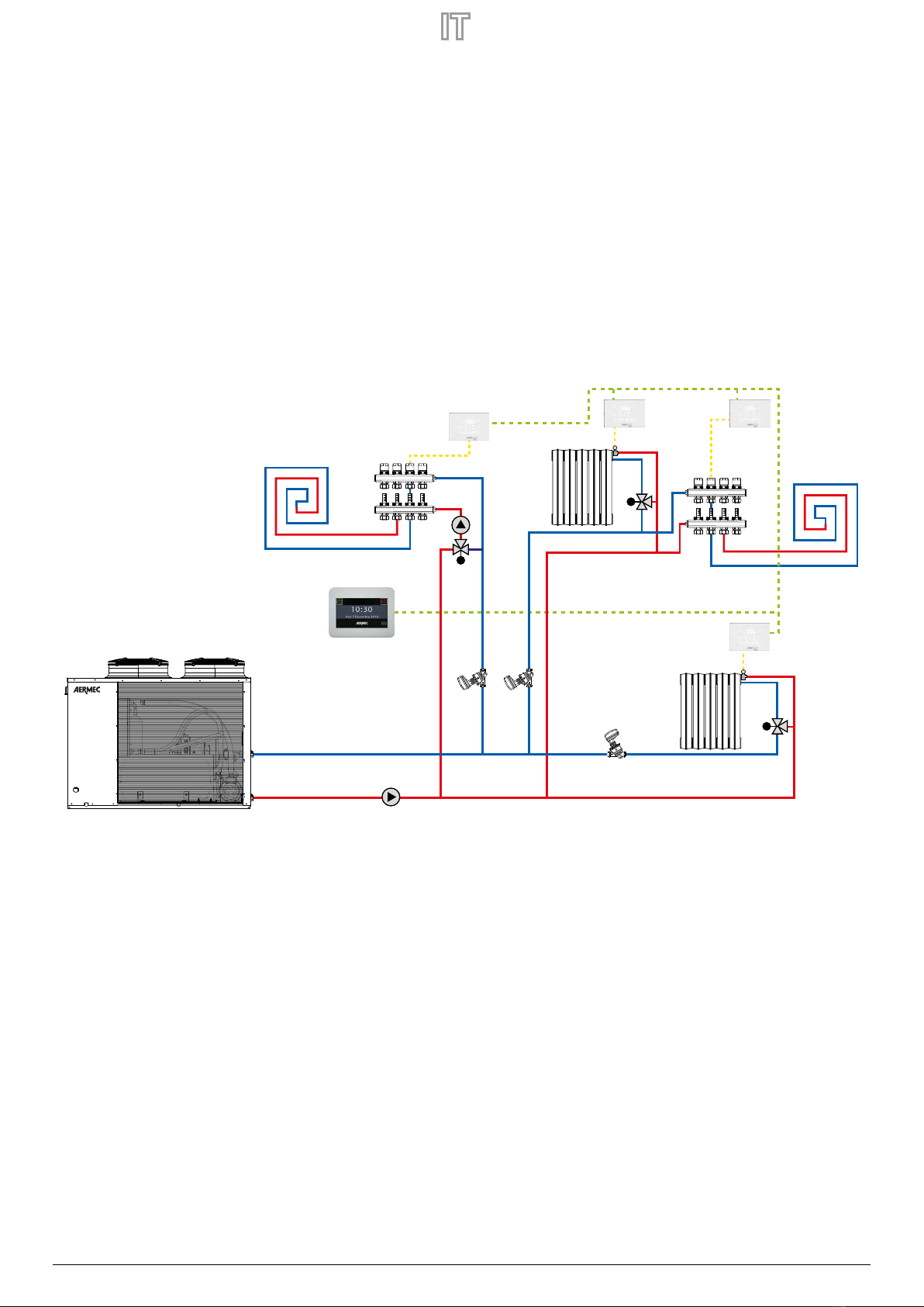
2. Tipologie di applicazioni.............................................................................................p.5
3. Interfaccia utente ..........................................................................................................p.6
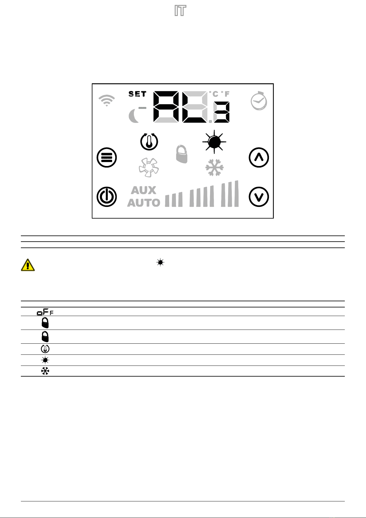
4. Display pannello VMF-FMD........................................................................................p.7
5. Menu parametrizzazione............................................................................................p.8
Parametri con password 3 ...............................................................................................................p.8
6. Cambio set di temperatura........................................................................................p.9
7. Visualizzazioni del pannello.................................................................................... p.10
Visualizzazione degli allarmi........................................................................................................ p.10
Visualizzazione di particolari condizioni di funzionamento............................................. p.10
8. Caratteristiche elettriche ......................................................................................... p.11
Esempio di connessione elettrica .............................................................................................. p.12
TABLE OF CONTENTS EN
1. Panel functionalities........................................................................................... p.13
2. Types of application........................................................................................... p.13
3. User interface ....................................................................................................... p.14
4. VMF-FMD panel display.................................................................................... p.15
5. Parametrisation menu....................................................................................... p.16
Parameters with password 3 ...............................................................................................p.16
6. Temperature set change................................................................................... p.17
7. Panel displays....................................................................................................... p.18
Alarms display...........................................................................................................................p.18
Specic functioning conditions display..........................................................................p.18
8. Electrical characteristics ................................................................................... p.19
Example of electrical connection ......................................................................................p.20
TABLE DES MATIÈRES FR
1. Fonctionnalités du panneau........................................................................................... p.21
2. Types d’applications .......................................................................................................... p.21
3. Interface utilisateur ............................................................................................................ p.22
4. Écran du panneau VMF-FMD .......................................................................................... p.23
5. Menu paramétrage ............................................................................................................ p.24
Paramètres avec mot de passe 3 ......................................................................................................... p.24
6. Changement du point de consigne de la température........................................ p.25
7. Achages du panneau..................................................................................................... p.26
Achage des alarmes.............................................................................................................................. p.26
Achage des conditions particulières de fonctionnement...................................................... p.26
8. Caractéristiques électriques............................................................................................ p.27
Exemple de connexion électrique ...................................................................................................... p.28
INHALTSVERZEICHNIS DE
1. Funktionsweise der Bedientafel.............................................................................................. S.29
2. Anwendungstypologien............................................................................................................ S.29
3. Benutzerschnittstelle.................................................................................................................. S.30
4. Display der VMF-FMD-Bedientafel......................................................................................... S.31
5. Menü Parametrierung ................................................................................................................ S.32
Parameter mit Passwort 3..................................................................................................................................S.32
6. Ändern des Temperatur-Sollwerts ......................................................................................... S.33
7. Anzeigen der Bedientafel.......................................................................................................... S.34
Alarmanzeige.........................................................................................................................................................S.34
Anzeige von besonderen Betriebsbedingungen......................................................................................S.34
8. Elektrische Merkmale.................................................................................................................. S.35
Beispiel für einen elektrischen Anschluss....................................................................................................S.36
ÍNDICE ES
1. Funcionalidad del panel........................................................................................... p.37
2. Tipos de aplicaciones................................................................................................ p.37
3. Interfaz de usuario ..................................................................................................... p.38
4. Pantalla del panel VMF-FMD .................................................................................. p.39
5. Menú de parametrización....................................................................................... p.40
Parámetros con contraseña 3...................................................................................................... p.40
6. Cambio de set de temperatura.............................................................................. p.41
7. Visualizaciones del panel......................................................................................... p.42
Visualización de las alarmas......................................................................................................... p.42
Visualización de condiciones especiales de funcionamiento.......................................... p.42
8. Características eléctricas.......................................................................................... p.43
Ejemplo de conexión eléctrica.................................................................................................... p.44

22/10 – 5905355_00 5
1 FUNZIONALITÀ DEL PANNELLO
Il pannello VMF-FMD è un termostato da incasso che, utilizzato in modalità stand alone o all'interno di un sistema centralizzato da supervisione (BMS), può gestire le esigenze impian-
tistiche in cui si vuole controllare un attuatore in funzione della temperatura ambiente.
Il pannello presenta alcuni parametri che permettono di adattarlo alle speciche esigenze impiantistiche.
2 TIPOLOGIE DI APPLICAZIONI
Nello specico il termostato VMF-FMD può essere impiegato per controllare:
— Testine di un pavimento radiante
— Valvole di zona
— Valvole di termo arredi
— Serrande motorizzate

6 22/10 – 5905355_00
3 INTERFACCIA UTENTE
1
2
3
4
Il pannello presenta 4 tasti di tipo capacitivo le cui funzioni sono di seguito riportate:
N° Tasto Funzione
1
Selezione del menù password
Conferma modica parametro o selezione del parametro
2
On/O del termostato
3
Incremento valore set temperatura ambiente o parametro selezionato nel menù utente
4
Decremento valore set temperatura ambiente o parametro selezionato nel menù utente

22/10 – 5905355_00 7
4 DISPLAY PANNELLO VMFFMD
Il pannello VMF-FMD presenta un ampio display che attraverso le icone identica le varie informazioni del sistema.
Di seguito si riporta la gura in cui sono descritti tutti i simboli presenti:
A Modalità cambio set funzionamento
B Temperatura/Set ambiente
C Visualizzazione C/°F
D Funzionamento a caldo del sistema
E Funzionamento a freddo del sistema
F Forzatura del modo di funzionamento da supervi-
sore
G Richiesta del termostato
A
B C
D
E
F
G

8 22/10 – 5905355_00
5 MENU PARAMETRIZZAZIONE
Per entrare nelle pagine di parametrizzazione si deve premere il tasto Mode/Select , dalla pagina PAS(password) si può selezionare il sottomenù idoneo al tipo di installazione e
alla necessità funzionale.
Sempre con il tasto Mode/Select si procede con l’inserimento della password che verrà scelta tramite i tasti Incrementa e Decrementa; alla ne la conferma potrà essere
data attraverso il tasto Mode/Select.
PARAMETRI CON PASSWORD 3
Parametro Descrizione Valore min Valore max Default Tipo
PASPagina password 0 999 --- ---
SEA
Parametro stagione di funzionamento:
0 1 0 ---
0: modalità rarescamento
1: modalità riscaldamento
E5b
Modica stagione di funzionamento da supervisione:
0 1 0 ---
0: blocco del cambio modo
1: abilitazione del cambio modo
LCdParametro standby LCD 0 2 0 ---
CF0
Parametro scelta °C/°F:
0 1 0 ---
0: visualizzazione in °C
1: visualizzazione in °F
AtACorrezione sonda di temperatura -5,0 +5,0 0 °C
dt5
Intervallo di scostamento del setpoint:
0 1 0 ---
0: scostamento +/- 6°C
1: scostamento +/- 3°C
SEt
Tipo di visualizzazione del setpoint:
0 1 0 ---
0: setpoint in valore assoluto
1: setpoint come scostamento
AddIndirizzo seriale Modbus 0 254 0 ---
Per scorrere la lista parametri è suciente agire sui tasti incrementa e decrementa.

22/10 – 5905355_00 9
6 CAMBIO SET DI TEMPERATURA
Per cambiare il set della temperatura ambiente è suciente seguire le tre operazioni (step) riportate nella gura sottostate:
STEP 1 STEP 3
STEP 2
Step 1: Premere il pulsante o per passare in modalità cambio set della temperatura.
Step 2: Con i pulsanti o si può modicare il set della temperatura ambiente.
Step3: Premere il pulsante oppure attendere 10 secondi per ritornare alla schermata principale.
Per le applicazioni“Stand Alone”i range del set di funzionamento sono:
Min. [°C] Max. [°C] Modalità di funzionamento
17.0 33.0 Freddo
12.0 28.0 Caldo
Per le applicazioni in cui è presente un sistema di supervisione (BMS) o un sistema di controllo d’impianto (VMF), il set visualizzato non è un valore assoluto ma uno scostamento relativo
al dato imposto dal sistema centralizzato:
Min. [°C] Max. [°C] Modalità di funzionamento
-6 +6 dt5 = 1
-3 +3 dt5 = 0

10 22/10 – 5905355_00
7 VISUALIZZAZIONI DEL PANNELLO
Il pannello VMF-FMD, come evidenziato nel paragrafo delle applicazioni, può essere usato in installazioni di diversa complessità e quindi si ha l’esigenza di prevedere delle visualizza-
zioni speciche per individuare eventuali anomalie o particolari condizioni di funzionamento dell’impianto.
VISUALIZZAZIONE DEGLI ALLARMI
Il pannello VMF-FMD prevede la visualizzazione di alcune anomalie che possono essere presenti nel termostato, questi malfunzionamenti sono indicati tramite una stringa“AL”seguita
da un codice, vedi esempio riportato di seguito:
La codica degli allarmi è rappresentata nella tabella seguente:
Codice allarme Descrizione
AL31Guasto sonda ambiente presente a bordo del pannello VMF-FMD
In caso di allarme antigelo si avrà la visualizzazione dell’icona lampeggiante.
VISUALIZZAZIONE DI PARTICOLARI CONDIZIONI DI FUNZIONAMENTO
Di seguito si riporta una tabella che descrive brevemente alcune combinazioni di visualizzazioni che rappresentano particolari condizioni di funzionamento del termostato:
Simbolo Stato simbolo Descrizione dello stato di funzionamento
ON Termostato disabilitato
ON Modo di funzionamento del termostato forzato da supervisore
LAMPEGGIANTE Il termostato è fuoriuscito dal blocco di funzionamento del supervisore (tempo massimo di 45 minuti)
ON Richiesta da termostato
ON Funzionamento a caldo del termostato
ON Funzionamento a freddo del termostato

22/10 – 5905355_00 11
8 CARATTERISTICHE ELETTRICHE
NOT USED
NOT USED
OUTPUT TRIAC
OUTPUT TRIAC
GND
A (T+) RS485
B (T-) RS485
C1 C0
I/O Funzione Caratteristiche elettriche
M1_1 Morsetto di alimentazione L/AC1 Vin: 230 Vac, 50/60 Hz, Imax: 1 A
M1_2 Morsetto di alimentazione N/AC2 Vin: 230 Vac, 50/60 Hz, Imax: 1 A
M1_3 Morsetto per riferimento di terra PE
M2_1 Morsetto uscita triac per controllo carichi Vin: 230 Vac, 50/60 Hz, Imax: 1 A
M2_2 Morsetto uscita triac per controllo carichi Vin: 230 Vac, 50/60 Hz, Imax: 1 A
M3_1 Morsetto seriale Uart RS485 A (T+) V max −9 [V] ÷ +14 [V]
M3_2 Morsetto seriale Uart RS485 B (T-) V max −9 [V] ÷ +14 [V]
M3_3 Morsetto seriale Uart RS485/TTL Slave GND

12 22/10 – 5905355_00
ESEMPIO DI CONNESSIONE ELETTRICA
Si riporta di seguito lo schema di connessione elettrica che può essere utilizzato per tutti i termostati VMF-FMD:
23OV 50Hz
LN
IG
VMF-FMD
GND
A
B
MODBUS
RTU RS485
C1
C0

22/10 – 5905355_00 13
1 PANEL FUNCTIONALITIES
The VMF-FMD panel is a ush-mounted thermostat that, when used in stand-alone mode or within a centralised supervisory system (BMS), can manage plant requirements
where an actuator is to be controlled according to room temperature.
The panel has a number of parameters that allow it to be adapted to specic plant requirements.
2 TYPES OF APPLICATION
Specically, the VMF-FMD thermostat can be used to control:
— Radiant oor heads
— Zone valves
— Heating furniture valves
— Motorised roller shutters

14 22/10 – 5905355_00
3 USER INTERFACE
1
2
3
4
The panel has 4 capacitive buttons, their funcions are listed below:
N° Button Function
1
Password menu selection
Conrm parameter change or parameter selection
2
Thermostat on/o
3
Increase room temperature set value or parameter selected in user menu
4
Decrease room temperature set value or parameter selected in user menu

22/10 – 5905355_00 15
4 VMFFMD PANEL DISPLAY
The VMF-FMD panel shows a large display which identies various system information by means of icons
The gure describing all the symbols is provided below:
A Operating set change mode
B Ambient temperature/set
C C/°F display
D Heat system operation
E Cool system operation
F Forcing the operating mode from supervisor
G Thermostat request
A
B C
D
E
F
G

16 22/10 – 5905355_00
5 PARAMETRISATION MENU
To enter the parameterisation pages, press the Mode/Select button the suitable submenu for the type of installation and the functional necessity can be selected from
the PAS(password) page.
Press the Mode/Select button to enter the password, which will be chosen using the Increase and Decrease buttons; at the end, conrm via the Mode/
Select button.
PARAMETERS WITH PASSWORD 3
Parameter Description Min value Max value Default Type
PAS
Password page 0 999 --- ---
SEA
Operating season parameter
0 1 0 ---
0: modalità rarescamento
1: modalità riscaldamento
E5b
Change of operating season from supervision:
0 1 0 ---
0: blocco del cambio modo
1: abilitazione del cambio modo
LCd
LCD standby parameter 0 2 0 ---
CF0
Selection parameter °C/°F:
0 1 0 ---
0: visualizzazione in °C
1: visualizzazione in °F
AtA
Temperature probe correction -5,0 +5,0 0 °C
dt5
Setpoint deviation interval:
0 1 0 ---
0: scostamento +/- 6°C
1: scostamento +/- 3°C
SEt
Display type of the setpoint:
0 1 0 ---
0: setpoint in valore assoluto
1: setpoint come scostamento
Add
Modbus serial address 0 254 0 ---
To scroll through the parameter list, simply use the increase and decrease buttons.

22/10 – 5905355_00 17
6 TEMPERATURE SET CHANGE
To change the room temperature set simply follow the three steps shown in the gure below:
STEP 1 STEP 3
STEP 2
Step 1: Press the button o to switch to temperature set change mode.
Step 2: With the buttons o the room temperature set can be changed.
Step3: Press the button or wait 10 seconds to return to the main screen.
The functioning set ranges for“Stand Alone”applications are:
Min. [°C] Max. [°C] Operating mode
17.0 33.0 Cooling
12.0 28.0 Heating
For the applications with a supervision system (BMS) or a system control system (VMF), the displayed set is not an absolute value but a relative dierence from the data set by
the centralised system:
Min. [°C] Max. [°C] Operating mode
-6 +6 dt5 = 1
-3 +3 dt5 = 0

18 22/10 – 5905355_00
7 PANEL DISPLAYS
The VMF-FMD panel, as highlighted in the application paragraph, can be used in installations of dierent complexity and therefore there is a need to include specic displays
to detect any anomalies or specic system functioning conditions.
ALARMS DISPLAY
The VMF-FMD panel includes the display of some anomalies which can be present in the thermostat, these faults are indicated through a string“AL“ followed by a code, see
example below:
The alarm codication is represented in the following table:
Alarm code Description
AL31VMF-FMD panel environmental probe fault
In the event of a frost alarm, the ashing icon will be displayed.
SPECIFIC FUNCTIONING CONDITIONS DISPLAY
Below you will nd a table briey describing some display combinations which represent specic thermostat functioning conditions:
Symbol Symbol status Functioning status description
ON Thermostat disabled
ON Thermostat operating mode forced by supervisor
BLINK The thermostat is outside the supervisor functioning block (maximum time 45 minutes)
ON Thermostat request
ON Thermostat heating mode functioning
ON Thermostat cooling mode functioning

22/10 – 5905355_00 19
8 ELECTRICAL CHARACTERISTICS
NOT USED
NOT USED
OUTPUT TRIAC
OUTPUT TRIAC
GND
A (T+) RS485
B (T-) RS485
C1 C0
I/O Function Electrical characteristics
M1_1 Power supply terminal L/AC1 Vin: 230 Vac, 50/60 Hz, Imax: 1 A
M1_2 Power supply terminal N/AC2 Vin: 230 Vac, 50/60 Hz, Imax: 1 A
M1_3 Terminal for earth reference PE
M2_1 Triac output terminal for load control Vin: 230 Vac, 50/60 Hz, Imax: 1 A
M2_2 Triac output terminal for load control Vin: 230 Vac, 50/60 Hz, Imax: 1 A
M3_1 Uart RS485 serial terminal A (T+) V max −9 [V] ÷ +14 [V]
M3_2 Uart RS485 serial terminal B (T-) V max −9 [V] ÷ +14 [V]
M3_3 Uart RS485/TTL Slave serial terminal GND

20 22/10 – 5905355_00
EXAMPLE OF ELECTRICAL CONNECTION
Below you will nd the electrical connection which may be used for all thermostats VMF-FMD:
23OV 50Hz
LN
IG
VMF-FMD
GND
A
B
MODBUS
RTU RS485
C1
C0
Table of contents
Languages:
Other AERMEC Recording Equipment manuals