AERMEC C-TOUCH User manual

22/05 – 4472015_01
Translation of Original instructions
www.aermec.com
User manual
NRB-Large
CARD PCO5 PANEL CTOUCH

This marking indicates that this product should not be disposed with other household wastes throughout the EU. To prevent possible harm to the envi-
ronment or human health from uncontrolled disposal of Waste Electrical and Electronic Equipment (WEEE), please return the device using appropriate
collection systems, or contact the retailer where the product was purchased. Please contact your local authority for further details. Illegal dumping of
the product by the user entails the application of administrative sanctions provided by law.
All specications are subject to change without prior notice. Although every eort has been made to ensure accuracy, Aermec shall not be held liable for any errors or
omissions.
SAFETY CERTIFICATIONS
Dear Customer,
Thank you for wanting to learn about a product Aermec. This product is the result of many years of experience and in-depth engineering research, and it is
built using top quality materials and advanced technologies.
The manual you are about to read is meant to present the product and help you select the unit that best meets the needs of your system.
However, please note that for a more accurate selection, you can also use the Magellano selection program, available on our website.
Aermec Aermec, always attentive to the continuous changes in the market and its regulations, reserves the right to make all the changes deemed necessary
for improving the product, including technical data.
Thank you again.
AERMEC S.p.A.

3
TABLE OF CONTENTS
1. Quick reference ...................................................................................p.5
2. Structure of the menus...................................................................p.6
Interacting with the graphic interface ...........................................p.6
Navigating between the program pages......................................p.6
Setting a numerical value for a parameter....................................p.7
Setting a value, selecting it from a list............................................p.7
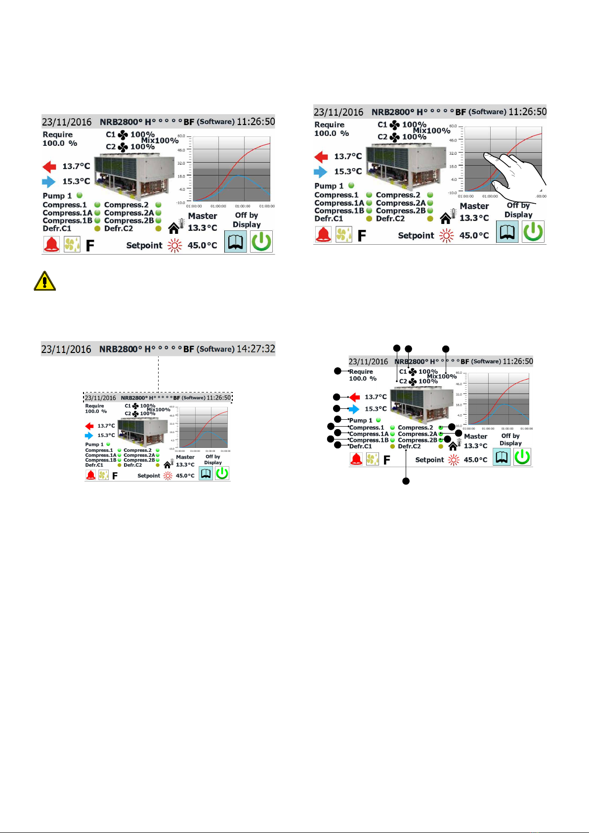
3. Main page (HOME) ............................................................................p.8
Data entered in the upper bar...........................................................p.8
Water inlet/outlet temperature chart.............................................p.8
Unit operating status information (real time data)....................p.8
Data entered in the lower bar, and navigation keys..................p.9
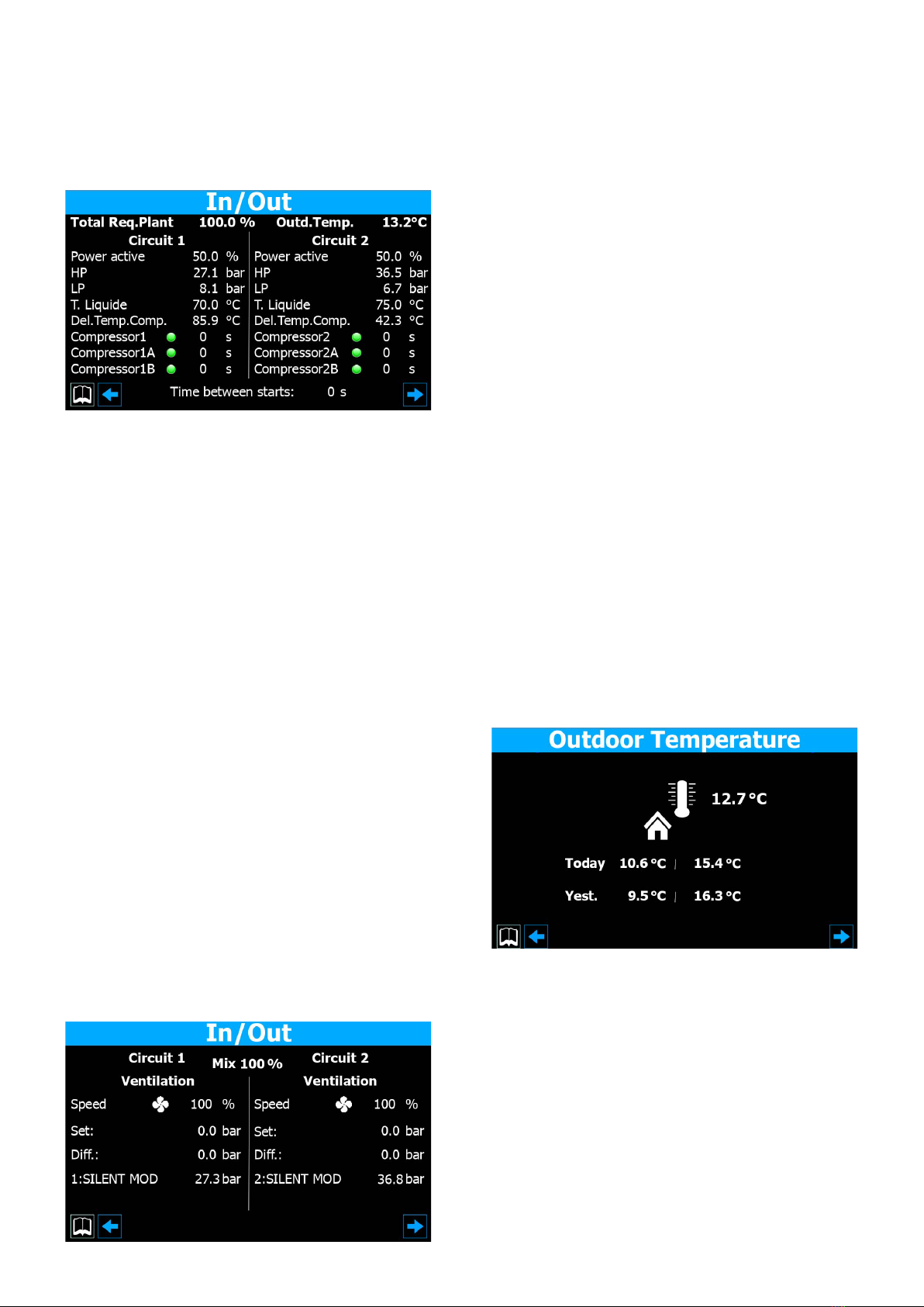
4. Input/output menu........................................................................ p.10
General input/output status ........................................................... p.10
Ventilation status................................................................................. p.10
Outside temperature status ............................................................ p.10
Defrosting status................................................................................. p.11
PCO5 analogue input status............................................................ p.11
uPC analogue input status............................................................... p.11
PCO5 digital input status.................................................................. p.12
PCO5 digital output status............................................................... p.12
uPC digital output status.................................................................. p.13
Status of inputs/outputs for pCOE expansion card ................ p.13
Status of inputs/outputs for total recovery or DK unit.......... p.13
5. ON/OFF menu................................................................................... p.14
Switching the unit ON/OFF ............................................................. p.14
6. System menu..................................................................................... p.14
Setting the operating mode and the main set-points........... p.14
Setting the secondary set-point and recovery (if available)
................................................................................................................... p.15
Setting the outside temperature for automatic
changeover............................................................................................ p.15
Setting the operating mode on the basis of the calendar
................................................................................................................... p.15
7. Installer menu ................................................................................... p.16
Entering the password for accessing the protected menu
................................................................................................................... p.16
Selecting the sub-menus ................................................................. p.16
Enabling On/O via digital input ID17........................................ p.16
Enabling and setting control via the remote supervisor
(BMS)........................................................................................................ p.16
Conguring the thermostat and the type of operating
set-point ................................................................................................. p.17
Conguring the climate curve........................................................ p.17
Conguring the antifreeze conditions ........................................ p.17
Conguring the antifreeze conditions and the recovery
pump (if installed)............................................................................... p.18
Congurazione dei ventilatori........................................................ p.18
Conguring the supplementary heaters and replacement
boiler (if installed) ............................................................................... p.18
Compressor operating log............................................................... p.19
Master Slave - Conguring power control in the case of
two-unit systems................................................................................. p.19
Conguring the Free-cooling unit (if installed)........................ p.19
Conguring the C-Touch clock and the pCO5 clock............... p.19
Conguring the automatic GMT/Daylight Saving Time
changeover............................................................................................ p.20
Conguring the calendar ................................................................. p.20
Software version - Information about the system .................. p.20
8. Alarm Menu........................................................................................ p.21
Main alarm page.................................................................................. p.21
Active alarms page ............................................................................. p.21
Alarm history ........................................................................................ p.21
List of alarms......................................................................................... p.22
9. Diagram menu.................................................................................. p.23

4
Chart showing temperature trend of inlet/outlet water on
heat exchanger .................................................................................... p.23
Chart showing trend of compressors on circuit 1................... p.23
Chart showing trend of compressors on circuit 2 (if
installed)................................................................................................. p.23
Chart showing trend of high/low pressure on Circuit 1........ p.23
Chart showing trend of high/low pressure on Circuit 2 (if
installed)................................................................................................. p.23
10. Summary menu................................................................................ p.24
Page relating to the cooling-only units (or heat pump
with cooling operation).................................................................... p.24
Page relating to the cooling-only units (or heat pump
with heating operation).................................................................... p.24
Page relating to the units with free-cooling (1)....................... p.24
Page relating to the units with free-cooling (2)....................... p.25
Page relating to the units with Recovery.................................... p.25
11. Time band menu ............................................................................. p.25
Page for creating timed programs................................................ p.25
12. Language menu............................................................................... p.26
Page for selecting the system language..................................... p.26
13. Help menu........................................................................................... p.26
14. Multi-purpose input menu........................................................ p.26
General setting of the u10 multi-purpose input...................... p.26
Setting for power Limitation function......................................... p.26
Setting for variable set-point function........................................ p.27
Setting for NTC signal type.............................................................. p.27

5
1 QUICK REFERENCE
This manual describes all the windows found in the control software of the C-Touch
panel, but the list below contains all the basic operations that the user might need,
referring him/her to the relative page of the manual where there is a description of
that specic function (for all other information, refer to the contents page):
A Switching the unit ON/OFF (5.1Switching the unit ON/OFFp.14)
B Selecting the operating mode (6.1Setting the operating mode and the main set-pointsp.14)
C Setting a main operating set-point (6.1Setting the operating mode and the main set-pointsp.14)
D Setting the time bands (11Time band menup.25)
E Applying a timed program (11.1Page for creating timed programsp.25)
F Changing the system language (12.1Page for selecting the system languagep.26)
A
B
C
D
E
F

6
2 STRUCTURE OF THE MENUS
With the C-touch panel, the user can manage all the operating parameters of the
unit via a touchscreen graphic interface. The use of the information is easy and
straightforward, thanks to the "home" page showing the main unit operating pa-
rameters. The more specic parameters and settings can be found in the various
menus, accessed via the relative selection page that identies each menu with a
specic icon. These icons are highlighted below:
Input/output menu
ON/OFF menu
System menu
Installer menu (password 0000)
Alarm Menu
Diagram menu
Summary menu
Time band menu
Language menu
Help menu (PROTECTED menu)
Multi-purpose input menu
2.1 INTERACTING WITH THE GRAPHIC INTERFACE
The unit command and control interface uses a touchscreen display. This interface
is designed to be simple and user-friendly; the absence of actual keys means the
program is managed purely by touching the screen directly, which makes it far
more accessible for the user. The software manages a great deal of information,
with the various items grouped into separate pages that in turn are managed via
specic menus, but there are certain fundamental features that apply to all the op-
erations, such as selecting a window, moving on to the next window, or entering a
precise numerical value. The basic operations that can be carried out via the touch-
screen interface of the C-Touch device are described below.
NB: The following pages show all the masks contained in the menus availa-
ble to the user; Tampering with the parameters in the installer menu could
cause the unit to malfunction, therefore it is recommended to have these
parameters changed only by personnel assigned to unit installation and
conguration.
2.2 NAVIGATING BETWEEN THE PROGRAM PAGES
As already mentioned on the previous pages, the unit operating information is
sub-divided into various menus, each containing several pages. The basic opera-
tions for navigating between the menus are as follows:
— Access a menu: to access a menu you must activate the menu selection page
by pressing the "open book" icon ( ) found on every page of the program.
Now, just press the icon that represents the specic menu you want to access
(for more information about which menus are activated by the various icons,
refer to the diagram on the previous page).
— Scroll to the next or previous page of a menu: once you have accessed a
menu, you can pass from one page to another by pressing the "right arrow" icon
() to go forward, or the "left arrow" icon ( ) to go back (unless the menu
in question has just one page).
— Return to the "Home" page: to go back to the main (home) page, press the
relative icon ( ); Not all the program pages contain this icon, but you can nd
it on the menu selection page so just go to that page (as explained in the rst
point of this list) and from there you can reach "Home".

7
2.3 SETTING A NUMERICAL VALUE FOR A PARAMETER
Many parameters (e.g. the seasonal operating set-points) require the user to enter
a numerical value. In these cases, proceed as follows:
1. Once you have accessed a page containing an editable numerical value (e.g.
the operating set-points), press on the value already displayed.
2. A numerical keypad will now appear, where you can enter a new value;
3. Press "Enter" on the keypad to conrm and apply the new value, or press "Esc"
to delete the operation.
Once you have selected the numerical value to be modied, the nu-
merical keypad will show the Minimum and Maximum values that
can be set for that parameter.
2.4 SETTING A VALUE, SELECTING IT FROM A LIST
Certain parameters (such as the operating mode) require the user to choose an op-
tion from a list. In these cases, proceed as follows:
1. Once you have accessed a page containing an editable value (e.g. the operat-
ing mode), press on the option already displayed;
2. A small window will now appear, with a list of options;
3. Select one of the options by pressing on it. Your choice will be highlighted by
a change of colour;
4. Press "OK" to apply the chosen option, or press "Cancel" to quit the selection
page without altering the previous value;
COOLING
HEATING
BY TEMP.OUTDOOR
BY DIGITAL INPUT
BY SUPERVISOR

8
3 MAIN PAGE HOME
The standard display during normal operation is the "Home" page. Depending on
the type of unit congured, from this window you can keep the main operating
parameters under control or access direct connections to certain operating menus.
We will analyse and explain below all the elements that can be viewed and/or man-
aged via the Home page.
ATTENTION: certain information is only visible if it is available on the unit
(for example data relating to the Free-cooling circuit).
3.1 DATA ENTERED IN THE UPPER BAR
— Date set on the system
— String corresponding to the unit congurator (for more information about the
unit congurator, refer to the technical manual of the unit itself).
— Time set on the system
Note:
The units have two dierent timers - one integrated in the C-touch panel and the
other relating to the electric control card of the units. These timers can have dif-
ferent time settings (which can be seen on the "Clock conguration" page of the
installer menu), to ensure the correct time is shown for any alarms saved in the log.
You are advised to check them regularly to make sure they coincide, synchronising
them if necessary.
The congured unit code is entered in the factory, and cannot be altered by the
user.
3.2 WATER INLET/OUTLET TEMPERATURE CHART
The chart on the homepage shows the temperature trend of the water entering and
leaving the unit. The colours will depend on the unit operating mode: in cooling
mode, BLUE indicates the outlet water and RED the inlet water; on the contrary,
in heating mode RED indicates the processed water and BLUE the water returning
from the system.
Click on the chart to directly open the "chart menu", where you can see a log of the
various charts available. To return to the main page, you must rst go to the menu
selection page and from there select "Home".
3.3 UNIT OPERATING STATUS INFORMATION REAL TIME
DATA
7
1
2
34
5
6
8
2
9
10
11
12
13
14
15
1. Percentage gure showing the power request from the system
2. Percentage gure showing the speed of the fans on circuit 1
3. Percentage gure showing the speed of the fans on circuit 2 (only visible if the
unit has 2 circuits)
4. Percentage gure showing the speed of the shared fans in V-BLOCK units (only
visible on V-BLOCK units)
5. Indicates the temperature of the water processed by the unit (real time gure)
6. Indicates the temperature of the water entering the unit (real time gure)
7. This label appears if the unit pump is active (if the unit has a pump component)
8. This label appears if unit compressor 1 is active
9. This label appears if unit compressor 1A is active (if installed)
10. This label appears if unit compressor 1B is active (if installed)
11. This label appears if defrosting is in progress on circuit 1
12. This label appears if unit compressor 2 is active (if installed)
13. This label appears if unit compressor 2A is active (if installed)
14. This label appears if unit compressor 2B is active (if installed)
15. This label appears if defrosting is in progress on circuit 2 (on two-circuit units
only)
Note: Much of the information in this section is linked to the type of unit: the pres-
ence of a second circuit or a hydronic side pump, or the number of compressors
managed by the system, will depend on the type of unit.

9
3.4 DATA ENTERED IN THE LOWER BAR, AND NAVIGATION
KEYS
1 32
4 5 6
8 9
10
7
1. Indicates whether the unit is MASTER or SLAVE (only visible if the unit is in-
stalled and congured as part of a multiple system set up for MASTER/SLAVE
management)
2. Value of the outside air temperature (real time value)
3. Current unit status (if the status is ON, no status will be indicated). The possible
info shown on the unit is:
— No info = Unit operating;
— General OFF via key = Unit switched o using key (7);
— Unit OFF via alarm = Unit switched o due to an alarm condition;
— OFF via supervisor = Unit switched o via BMS;
— OFF via time bands = Unit switched o due to the current time band setting;
— OFF via digital input = Unit switched o due to a digital input signal (ID17);
— Antifreeze = Unit operating in antifreeze mode;
— OFF via Master = Unit switched o via the MASTER unit;
— Outside operating limits = Unit switched o because it was working outside its
operating limits (for more information about the unit operating limits, refer to
the technical manual of the unit);
— Boiler replacement = Unit switched o because replaced by the boiler for hot
water production;
4. This icon indicates the current set-point being used (summer or winter) on the
basis of the selected operating mode
5. Indicates the current value for the operating set-point
6. Press this key to visualise the menu selection page
7. Press this key to switch the unit ON or OFF directly
8. This icon is displayed if there is an active alarm on the system - press it to view
the alarm menu
9. This icon indicates that the defrosting cycle is in progress (on at least one of the
circuits, in the case of two-circuit units) - press it to view the defrosting page on
the Input/Output menu
10. If visible, this icon indicates that Free-cooling mode is currently active (for
Free-cooling units only)
Note: If the system uses a MASTER/SLAVE conguration, remember that up to two
units can be managed with a "pLAN" serial connection (the address of the C-touch
MASTER panel must be "3", and that of the SLAVE "4"). It is recommended that the
two units - Master and Slave - are the same (same software version), so they can be
used in a balanced manner.
WARNING: it is essential that the Master and Slave units have the same
software version.

10
4 INPUT/OUTPUT MENU
The input/output menu shows many of the values measured by the various probes
and transducers on the unit. You cannot set any values via this menu, but it gives
important operating information such as the defrosting status and so on.
4.1 GENERAL INPUT/OUTPUT STATUS
This mask displays:
— Percentage value showing the current power request from the system
— Current outside temperature value
— Percentage value of the current load on circuit 1
— Current pressure value measured on the high-pressure side of the refrigerant
circuit
— Current pressure value measured on the low-pressure side of the refrigerant
circuit
— Current temperature value measured on the low-pressure side of the refrigerant
circuit
— Current temperature value measured on the high-pressure side of the refrig-
erant circuit
— Indication of the status (ON or OFF) of the compressors of circuit 1; if a compres-
sor is ON, there will be a green dot next to the label. For each compressor, there
is also a value in seconds, indicating (with a countdown) the minimum ON or
OFF time (in both cases, if the value is 0s this means the compressor has already
respected the minimum ON or OFF time and can respond to a request from the
system instantaneously).
— Indicates the minimum time that must pass between two compressor peaks;
the time is shown by means of a countdown, after which consent for the next
compressor peak is enabled.
— Percentage value of the current load on circuit 2 (if installed)
— Current pressure value measured on the high-pressure side of refrigerant circuit
2 (if installed)
— Current pressure value measured on the low-pressure side of refrigerant circuit
2 (if installed)
— Current temperature value measured on the low-pressure side of refrigerant
circuit 2 (if installed)
— Current temperature value measured on the high-pressure side of refrigerant
circuit 2 (if installed)
— Indication of the status (ON or OFF) of the compressors of circuit 2; if a compres-
sor is ON, there will be a green dot next to the label. For each compressor, there
is also a value in seconds, indicating (with a countdown) the minimum ON or
OFF time (in both cases, if the value is 0s this means the compressor has already
respected the minimum ON or OFF time and can respond to a system request
instantaneously).
4.2 VENTILATION STATUS
This mask displays:
— Percentage value of the current speed of the fans on circuit 1
— Current pressure value measured for the operating set-point of the fans on cir-
cuit 1
— Current pressure value measured for the dierential to be applied to the operat-
ing set-point of the fans on circuit 1
— Status of the fans on circuit 1. This status may be:
O = Fans switched o;
Pre-ventilation = Indicates the pre-empted switch-on of the fans in relation to the
compressors;
High pressure = Indicates that the check on the basis of high pressure is currently
active;
Post-ventilation = Indicates the ventilation phase after compressor switch-o;
Antifreeze = Indicates the ventilation phase for preventing the build-up of snow
and the formation of ice;
Defrosting = Indicates the defrosting phase;
Low pressure = Indicates that the check on the basis of low pressure is currently
active;
Maximum speed = Indicates that the fans are currently turning at their maximum
speed;
Low noise = Indicates that partialised speed is active, to reduce the noise level;
— Percentage value of the current speed of the fans on circuit 2 (if installed)
— Current pressure value measured for the operating set-point of the fans on cir-
cuit 2 (if installed)
— Current pressure value measured for the dierential to be applied to the operat-
ing set-point of the fans on circuit 2 (if installed)
— Status of the fans on circuit 2 (if installed). This status may be:
O = Fans switched o;
Pre-ventilation = Indicates the pre-empted switch-on of the fans in relation to the
compressors;
High pressure = Indicates that the check on the basis of high pressure is currently
active;
Post-ventilation = Indicates the ventilation phase after compressor switch-o;
Antifreeze = Indicates the ventilation phase for preventing the build-up of snow
and the formation of ice;
Defrosting = Indicates the defrosting phase;
Low pressure = Indicates that the check on the basis of low pressure is currently
active;
Maximum speed = Indicates that the fans are currently turning at their maximum
speed;
Low noise = Indicates that partialised speed is active, to reduce the noise level;
4.3 OUTSIDE TEMPERATURE STATUS
This mask displays:
— Current temperature value measured for the outside air
— Minimum outside air temperature recorded today
— Maximum outside air temperature recorded today
— Minimum outside air temperature recorded yesterday
— Maximum outside air temperature recorded yesterday

11
4.4 DEFROSTING STATUS
1. Indicates the current defrosting status on circuit 1. The possible values are:
— Disabled = No defrosting active;
— Bypass = Indicates that the bypass phase is currently active, following compres-
sor start-up;
— Decay calculation = Indicates that the pressure decay calculation is currently
in progress;
— Cycle reversal standby = Indicates that the pause is active, prior to the cycle
valve reversal;
— Defrosting start-up = Indicates that the defrosting cycle is beginning;
— Defrosting in progress = Indicates that the defrosting cycle is currently in pro-
gress;
— Defrosting end = Indicates that the defrosting cycle is ending;
— First defrosting = Indicates that the rst defrosting after a blackout is active;
2. Gives additional information about the defrosting status of circuit 1. This in-
formation may be:
— High outside temperature = Indicates that the outside air temperature is above
the defrosting enabling threshold;
— Circuit OFF = Indicates that the circuit compressors are switched o and de-
frosting is disabled;
— BP above limit threshold = Indicates that the low pressure value ("BP") is above
the limit threshold for triggering the defrosting cycle;
— Min time between defrosting cycles = Indicates that the defrosting cycle is cur-
rently disabled in order to respect the minimum time between two cycles;
— CP start-up = Indicates that the compressor has just been started up and the
bypass time before calculating the pressure decay is in progress;
— New BP reference = Indicates that a new low pressure value has been taken as
the reference for calculating the decay;
— Start-up for BP limit = Indicates that defrosting has been activated in order to
exceed the low pressure limit threshold;
— Start-up for P-delta = Indicates that defrosting has been activated in order to
exceed the low pressure decay value;
— Liquid temp. OK = Indicates that the liquid temperature has exceeded the
threshold for determining the end of the defrosting cycle;
— Min. defrosting times = Indicates that defrosting continues until the minimum
set time has been exceeded, even if the output conditions have already been
reached;
— Standby for other circuit = In the case of a single ventilation unit, indicates the
phase in which the circuit that ends the defrosting cycle rst switches o, wait-
ing for the other circuit to end too;
— First start-up bypass = Indicates that the rst defrosting cycle after a blackout
can only start after the compressor has been working for a specic time;
— Low liquid temp. = Indicates that the liquid temperature is below the threshold
for determining the end of the defrosting cycle;
— Start-up for TGP = Indicates that the defrosting cycle has been activated be-
cause the temperature threshold for the force gas has been exceeded;
— Forced = In the case of a single ventilation unit, indicates that the circuit has
been forced to defrost by the other circuit.
3. Indicates the defrosting times for circuit 1
4. Indicates the average low pressure value on circuit 1
5. Indicates the accumulated P-delta for determining defrosting activation on
circuit 1
6. Indicates the liquid temperature value for determining the defrosting end on
circuit 1
7. The same as point (1), but with reference to circuit 2 (if installed)
8. The same as point (2), but with reference to circuit 2 (if installed)
9. Indicates the defrosting times for circuit 2 (if installed)
10. Indicates the average low pressure value on circuit 2 (if installed)
11. Indicates the accumulated P-delta for determining defrosting activation on
circuit 2 I(if installed)
12. Indicates the liquid temperature value for determining the defrosting end on
circuit 2 (if installed)
4.5 PCO5 ANALOGUE INPUT STATUS
1. Indicates the current temperature value measured on the evaporator inlet
2. Indicates the current temperature value measured on the evaporator outlet
3. Indicates the current outside air temperature
4. Indicates the current temperature measured on the high-pressure side of cir-
cuit 1
5. Indicates the current high-pressure value of circuit 1
6. Indicates the current low-pressure value of circuit 1
7. Indicates the current temperature measured on the high-pressure side of cir-
cuit 2
8. Indicates the current high-pressure value of circuit 2
9. Indicates the current low-pressure value of circuit 2
4.6 UPC ANALOGUE INPUT STATUS
1. Not used
2. Not used
3. Not used
4. Not used
5. Not used
6. This gure may refer to various values, depending on the type of unit:
— Unit with total heat recovery = Indicates the temperature of the water entering
the total recovery unit;
— Free-cooling unit = Indicates the inlet temperature on the Free-cooling unit;
7. This gure may refer to various values, depending on the type of unit:
— Unit with total recovery = Indicates the temperature of the water leaving the
total recovery unit (heat exchanger 1);
— Free-cooling unit (glycol-free) = Indicates the outlet temperature on the
Free-cooling unit (glycol-free);
8. This gure may refer to various values, depending on the type of unit:
— Unit with total recovery = Indicates the temperature of the water leaving the
total recovery unit (heat exchanger 2);
— Free-cooling unit = Indicates the temperature measured by the probe on the
intermediate heat exchanger;
9. Indicates the current temperature value for water leaving evaporator 2
10. Not used
11. Indicates the current water temperature on the common evaporator outlet
12. Not used

12
4.7 PCO5 DIGITAL INPUT STATUS
1. Indicates the status of the evaporator ow switch
2. Indicates the status of the high-pressure switch for circuit 1
3. Indicates the status of the thermal protection on fan 1
4. Indicates the status of the phase monitor
5. Indicates the status of the thermal protection on compressor 1 (circuit 1)
6. Indicates the status of the thermal protection on compressor 2 (circuit 1)
7. Indicates the status of the thermal protection on compressor 3 (circuit 1)
8. Indicates the status of the high-pressure switch for circuit 2
9. Indicates the status of the thermal protection on fan 2
10. Indicates the setting for the second set-point
Closed = normal operation; Open = fault in progress;
11. Indicates the status of the thermal protection on compressor 1 (circuit 2 if
installed)
12. Indicates the status of the thermal protection on compressor 2 (circuit 2 if
installed)
13. Indicates the status of the thermal protection on compressor 3 (circuit 2) (if
installed)
14. Indicates the status of the thermal protection on evaporator pump 1
15. Indicates the status of the thermal protection on evaporator pump 2
Closed = normal operation; Open = fault in progress;
16. Indicates the setting for the remote season changeover command
17. Indicates the setting for the remote ON/OFF command
18. Indicates the setting for the multi-purpose input
Closed = input enabled; Open = input not enabled;
4.8 PCO5 DIGITAL OUTPUT STATUS
1. Indicates the status of pump 1
2. Indicates the status of compressor 1 (circuit 1)
3. Indicates the status of compressor 2 (circuit 1)
4. Indicates the status of compressor 3 (circuit 1)
5. Indicates the status of the liquid solenoid valve (circuit 1)
6. Indicates the status of the reverse cycle valve (circuit 1)
7. Indicates the status of the fans on circuit 1
8. Indicates the status of the "serious alarm" signal
9. Indicates the status of compressor 1 (circuit 2)
10. Indicates the status of compressor 2 (circuit 2)
11. Indicates the status of compressor 3 (circuit 2)
12. Indicates the status of the liquid solenoid valve (circuit 2)
13. Indicates the status of the fans on circuit 2
14. Indicates the status of the reverse cycle valve (circuit 2)
15. Indicates the status of the thermostat bypass solenoid valve (circuit 1)
16. Indicates the status of the thermostat bypass solenoid valve (circuit 2)
17. Indicates the status of the antifreeze heater:
18. Indicates the status of pump 2
Closed = load operating; Open = load not operating;
19. Indicates the voltage value applied to the DCP1 modulating fan unit (from 0
to 10,00V)
20. Indicates the voltage value applied to the DCP2 modulating fan unit (from 0
to 10,00V)
21. Indicates the voltage value applied to the DCP3 (or DCP1+DCP2) modulating
fan unit (from 0 to 10,00V)
22. Indicates the voltage value applied to the modulating fan unit of circuit 1 that
switches o in the event of low outside temperatures

13
4.9 UPC DIGITAL OUTPUT STATUS
1. Indicates the status of the coil disconnector valve on circuit 1
2. Can indicate the (Closed = operating; Open = not operating) status of various
loads, depending on the unit conguration:
— Unit with total recovery = status of the recovery exchanger resistor;
— Free-cooling unit (glycol-free) = status of the heater (glycol side)
3. Can indicate the (Closed = operating; Open = not operating) status of various
loads, depending on the unit conguration:
— Unit with total recovery = external recovery pump;
— Free-cooling unit (glycol-free) = coil bleed valve on circuit 1;
4. Can indicate the (Closed = operating; Open = not operating) status of various
loads, depending on the unit conguration:
— Unit with total recovery = bleed valve on circuit 1 (from recovery unit);
— Free-cooling unit (glycol-free) = coil bleed valve on circuit 1;
5. Can indicate the (Closed = operating; Open = not operating) status of various
loads, depending on the unit conguration:
— Unit with total recovery = bleed valve on circuit 1 (from condenser);
— Free-cooling unit (glycol-free) = coil bleed valve on circuit 2;
6. Can indicate the (Closed = operating; Open = not operating) status of various
loads, depending on the unit conguration:
— Unit with total recovery = bleed valve on circuit 2 (from recovery unit);
— Free-cooling unit (glycol-free) = coil bleed valve on circuit 2;
7. Can indicate the (Closed = operating; Open = not operating) status of various
loads, depending on the unit conguration:
— Unit with total recovery = bleed valve on circuit 2 (from condenser)
— Free-cooling unit (glycol-free) = 3-way valve (on Free-cooling);
8. Can indicate the (Closed = operating; Open = not operating) status of various
loads, depending on the unit conguration:
— Unit with total recovery = 3-way valve on total heat recovery unit, circuit 1;
— Free-cooling unit (glycol-free) = coil disconnector valve on circuit 1
9. Can indicate the (Closed = operating; Open = not operating) status of various
loads, depending on the unit conguration:
— Unit with total recovery = 3-way valve on total heat recovery unit, circuit 2;
— Free-cooling unit (glycol-free) = coil disconnector valve on circuit 2;
10. Indicates the status of the coil disconnector valve on circuit 2 (for Free-cooling
units)
11. Can indicate the (Closed = operating; Open = not operating) status of various
loads, depending on the unit conguration:
— Unit with total recovery = second solenoid valve;
— Free-cooling unit (glycol-free) = pump (glycol side);
12. Indicates the status of the second solenoid valve (for units with total heat
recovery)
Closed = load operating; Open = load not operating;
4.10 STATUS OF INPUTS/OUTPUTS FOR PCOE EXPANSION
CARD
1. B1: Indicates the current temperature measured by the liquid probe on circuit 1
2. B2: Indicates the current temperature measured by the liquid probe on circuit 2
3. B3: Indicates the current temperature measured by the accumulation tank
probe
4. B4: Not used
5. Can indicate the (Closed = operating; Open = not operating) status of various
loads, depending on the unit conguration:
— Unit with supplementary heater = supplementary heaters (RI1);
— Free-cooling unit (glycol-free) = consent for replacement boiler;
6. Indicates the status of the RI2/RI3 supplementary heaters (for units with sup-
plementary heaters)
7. Indicates the status of the tray heater
8. Indicates the status of the 3-way valve for domestic hot water (requested via
modbus)
Closed = load operating; Open = load not operating;
4.11 STATUS OF INPUTS/OUTPUTS FOR TOTAL RECOVERY
OR DK UNIT
— Indicates the current temperature of water entering the total recovery unit (if
available)
— Indicates the current temperature of water leaving the total recovery unit (if
available)
— Percentage value of the current power request to the total recovery unit (if avail-
able)
— Indicates the current temperature measured on the common outlet of the two
evaporators (if available)
— Indicates the current temperature of water leaving evaporator 1 (if available)
— Indicates the current temperature of water leaving evaporator 2 (if available)

14
5 ON/OFF MENU
The ON/OFF menu is used to switch the unit on or o. It also provides further infor-
mation about the current status of the machine.
5.1 SWITCHING THE UNIT ON/OFF
— System status. This status may be:
No info = Unit operating;
General OFF via key = Unit switched o via the interface;
Unit OFF via alarm = Unit switched o due to an alarm condition;
OFF via supervisor = Unit switched o via BMS;
OFF via time bands = Unit switched o due to the current time band setting;
OFF via digital input = Unit switched o due to a digital input signal (ID17);
Antifreeze = Unit operating in antifreeze mode;
OFF via Master = Unit switched o via the MASTER unit;
Outside operating limits = Unit switched o because it was working outside its
operating limits (for more information about the unit operating limits, refer to the
technical manual of the unit);
Boiler replacement = Unit switched o because replaced by the boiler for hot water
production;
— Indicates the current value selected (YES = Unit ON; NO = Unit OFF)
— Status of the recovery circuit (if installed). This status may be:
No info = Unit operating;
General OFF via key = Unit switched o via the interface;
Unit OFF via alarm = Unit switched o due to an alarm condition;
OFF via supervisor = Unit switched o via BMS;
OFF via time bands = Unit switched o due to the current time band setting;
OFF via digital input = Unit switched o due to a digital input signal (ID17);
Antifreeze = Unit operating in antifreeze mode;
OFF via Master = Unit switched o via the MASTER unit;
Outside operating limits = Unit switched o because it was working outside its
operating limits (for more information about the unit operating limits, refer to the
technical manual of the unit);
Boiler replacement = Unit switched o because replaced by the boiler for hot water
production;
6 SYSTEM MENU
The SYSTEM menu is used to set the operating mode and the set-point values for
the various modes.
6.1 SETTING THE OPERATING MODE AND THE MAIN SET
POINTS
1. Enable:
Indicates which type of adjustment is currently active on the unit. This may be:
— OFF = The unit is not producing water;
— ON = Unit adjustment is based on the main probe, according to the system set-
point;
— ON with Set 2 = Unit adjustment is based on the main probe, according to set-
point 2 (which can also be activated via digital input ID10, or the time bands);
— Time bands = Unit adjustment is based on the timed program currently ac-
tive (for more information about the timed programs, refer to the "Time band
menu");
2. Mode selection:
Indicates which operating mode is currently active on the unit. This may be as fol-
lows (the choice is only available for heat pump units):
— Cooling = The unit produces cold water on the basis of the current operating
set-point;
— Heating = The unit produces hot water on the basis of the current operating
set-point;
— Via ext. temp. = The unit chooses whether to activate cooling mode or heating
mode on the basis of the outside air temperature;
— Via dig. input = The unit chooses whether to activate cooling mode or heating
mode (Open = cooling; Closed = heating) on the basis of the status of digital
input ID16;
— Via superv. = The mode is set by the supervisor (BMS);
— Via calendar = The mode is set according to the value shown in the window (of
this menu) for the dates when cooling or heating mode should be activated;
3. Setpoint 1:
Indicates the current value of the main cooling set-point;
Indicates the current value of the main heating set-point (on heat pump only);

15
6.2 SETTING THE SECONDARY SETPOINT AND RECOVERY
IF AVAILABLE
1. Setpoint 2:
Indicates the current value of the secondary cooling set-point;
Indicates the current value of the secondary heating set-point (on heat pump only);
2. Recovery Enable Setpoint:
Indicates the current setting for recovery (YES = recovery enabled; NO = recovery
disabled);
Indicates the current value of the recovery set-point (if installed);
6.3 SETTING THE OUTSIDE TEMPERATURE FOR
AUTOMATIC CHANGEOVER
— Indicates the current outside air temperature at which cooling mode will be
activated;
— Indicates the current outside air temperature at which heating mode will be
activated (on heat pump only);
6.4 SETTING THE OPERATING MODE ON THE BASIS OF THE
CALENDAR
— Indicates the day of the month on which cooling mode will be activated
— Indicates the month in which cooling mode will be activated
— Indicates the day of the month on which heating mode will be activated (heat
pump only)
— Indicates the month in which heating mode will be activated (heat pump only)

16
7 INSTALLER MENU
The INSTALLER menu is used to access many of the settings for operating and ad-
justing the unit; it may, however, contain parameters that should only be modied
by persons responsible for maintenance and/or assistance on the unit or system,
and for this reason it's protected by a password.
USER PASSWORD: 0000
7.1 ENTERING THE PASSWORD FOR ACCESSING THE
PROTECTED MENU
1
2
3
1. This key is used to quit the window and go back to the menu selection page
2. Indicates the current value of the password to be used for accessing the in-
staller menu
3. This key is used to conrm the access password entered
7.2 SELECTING THE SUBMENUS
1. Input Enable:
This key is used to access the "Input enabling" sub-menu
2. Probe Regulation:
This key is used to access the "Probe adjustment and set-point" sub-menu
3. Fans:
This key is used to access the "Fans" sub-menu
4. Hour counters:
This key is used to access the "Hour-counter and Peak-counter" sub-menu
5. Freecooling - Glycol Free:
This key is used to access the "Free-cooling (glycol-free)" sub-menu
6. BMS Supervision:
This key is used to access the "BMS supervision" sub-menu
7. Antifreeze Conguration:
This key is used to access the "Antifreeze and pump conguration" sub-menu
8. Supplementary heaters/replacement boiler:
This key is used to access the "Supplementary heaters and replacement boiler" sub-
menu
9. Master - Slave:
This key is used to access the "Master-Slave" sub-menu
10. Software version/clock conguration:
This key is used to access the "Software version and clock conguration" sub-menu
7.3 ENABLING ON/OFF VIA DIGITAL INPUT ID17
Indicates the current setting for the "On/O via digital input ID17" function (YES =
function enabled; NO = function disabled)
7.4 ENABLING AND SETTING CONTROL VIA THE REMOTE
SUPERVISOR BMS
— Indicates the current setting for changeover via the supervisor (YES = function
enabled; NO = function disabled)
— Indicates the current setting for ON/OFF via the supervisor (YES = function ena-
bled; NO = function disabled)
— May indicate the current protocol selected for communication between the unit
and BMS. The protocols available are:
Modbus = RS485 modbus supervisor;
Carel = communication protocol for controlling the expansion cards;
pCOWeb = communication protocol for the pCOWeb expansion card;
Lon = communication protocol for controlling the Lon expansion cards;
Modbus Ext = extended modbus communication protocol (if you select this pro-
tocol, you will have the same addresses available on BMS2 for AERNET or another
supervisor);
— Indicates the current communication speed between the unit and the supervi-
sion system BMS1. The values that can be set are: 1200, 19200 or 38400 Baud
— Indicates the current number of stop bits for communication between the unit
and the supervision system BMS1. The values that can be set are: 1 or 2
— Indicates the current address assigned to the unit for communicating with the
remote supervisor BMS1
— Indicates the current communication speed between the unit and the supervi-
sion system BMS2. The values that can be set are: 1200, 19200 or 38400 Baud
— Indicates the current number of stop bits for communication between the unit
and the supervision system BMS2. The values that can be set are: 1 or 2
— Indicates the current address assigned to the unit for communicating with the
remote supervisor BMS2

17
7.5 CONFIGURING THE THERMOSTAT AND THE TYPE OF
OPERATING SETPOINT
— Indicates which probe should be used for the thermostat control of the pro-
cessed water. The value can be:
OUTLET (U2) = thermostat control will be carried out on the evaporator outlet
probe;
INLET (U1) = thermostat control will be carried out on the evaporator inlet probe;
COMMON OUTLET PROBE = thermostat control will be carried out on the probe on
the common outlet of the evaporators (if envisaged);
ACCUMULATION (U1) = thermostat control will be carried out on the accumulation
tank probe (if installed);
— Indicates the type of adjustment to be applied to the thermostat control. The
value can be:
PROP+INT = PROPORTIONAL + INTEGRAL adjustment will be used;
PROPORTIONAL = PROPORTIONAL adjustment will be used;
— Indicates the value assigned to the integration time, used to calculate the in-
tegral error
— Used to select the type of set-point to be used for cooling. The possible values
are:
FIXED SET-POINT = the adjustment will use a xed set-point with a value dened by
the user on the relative page of the "System menu";
CLIMATE CURVE = the adjustment will be made automatically, calculating the set-
point on the basis of the outside temperature (according to the setting made on the
"climate curve" page of this menu);
— Indicates the value assigned to the dierential used in cooling mode
— Used to select the type of set-point to be used for heating. The possible values
are:
FIXED SET-POINT = the adjustment will use a xed set-point with a value dened by
the user on the relative page of the "System menu";
CLIMATE CURVE = the adjustment will be made automatically, calculating the set-
point on the basis of the outside temperature (according to the setting made on the
"climate curve" page of this menu);
— Indicates the value assigned to the dierential used in heating mode
— Indicates the value assigned to the dierential used for heat recovery
— Indicates the maximum temperature of the water leaving the recovery unit, be-
yond which recovery mode is forcedly abandoned.
7.6 CONFIGURING THE CLIMATE CURVE
1. Indicates the current value of the cooling set-point, calculated on the basis of
the climate curve
2. Indicates the value to be assigned to the compensation set-point for the
climate curve used in cooling mode. This value will be subtracted from the
set-point dened by the user in the system menu, and associated with the
maximum outside air temperature specied in parameter (4)
3. Indicates the minimum outside air temperature (the starting point of the cli-
mate curve in cooling mode) to which set-point 1 (cooling) (dened by the
user in the system menu) must correspond
4. Indicates the maximum outside air temperature (the end point of the climate
curve in cooling mode) to be associated with the result of the subtraction of
set-point 1 (dened by the user in the system menu) from the compensation
set-point dened in parameter (2)
5. Indicates the current value of the heating set-point, calculated on the basis of
the climate curve
6. Indicates the value to be assigned to the compensation set-point for the cli-
mate curve used in heating mode. This value will be subtracted from the set-
point dened by the user in the system menu, and associated with the maxi-
mum outside air temperature specied in parameter (7)
7. Indicates the minimum outside air temperature (the starting point of the cli-
mate curve in heating mode) to which set-point 1 (heating) (dened by the
user in the system menu) must correspond
8. Indicates the maximum outside air temperature (the end point of the climate
curve in heating mode) to be associated with the result of the subtraction of
set-point 1 (dened by the user in the system menu) from the compensation
set-point dened in parameter (6)
Logic used for calculating the set-point via climate curve
°C
°C
Setpoint (A)
Set-point (A) - Comp.
set-point
External air
(minimum)
External air
(maximum)
1. The set-point (A) indicates the value dened (in both cooling and heating
mode, given that the calculation logic is the same) for normal operation (re-
member that this setting is dened on the rst page of the system menu);
2. The set-point (A) is dened so as to correspond to the minimum outside air
temperature (specied in the relative parameter on the climate curve (cooling/
heating) page;
3. The maximum outside air temperature (specied in the relative parameter on
the climate curve (cooling/heating) page) is associated with the result of the
subtraction of set-point (A) from the compensation set-point (dened on the
climate curve (cooling/heating) page);
4. For outside air temperatures lower than the value indicated as "minimum", the
operating set-point will be equal to the set-point (A);
5. For outside air temperatures between the minimum and maximum indicated,
the set-point will be calculated automatically on the basis of the straight sec-
tion of the climate curve;
6. For outside air temperatures higher than the maximum value, the operating
set-point will be the result of the subtraction of set-point (A) from the com-
pensation set-point;
7.7 CONFIGURING THE ANTIFREEZE CONDITIONS
— Indicates the temperature value for thermostat control (evaporator inlet or out-
let), below which the antifreeze alarm is activated

18
— Indicates the value of the dierential, to be added to the inlet temperature on
the recovery tank (if installed), for quitting the recovery antifreeze alarm con-
dition
— This value is used to choose whether to automatically switch on the pump if the
antifreeze heater is activated (YES = pumps activated together with the heater;
NO = pumps not activated)
— This value is used to choose whether to activate the cyclic pump activation
function on the basis of the outside temperature. This prevents the formation
of ice if the outside temperature falls very low (YES = cyclic pump activation
enabled; NO = cyclic pump activation not enabled)
— Indicates the time gap between two consecutive fan switch-on operations (if
cyclic fan activation is enabled)
— Indicates the duration of the pump cycle (if cyclic pump activation is enabled)
— Indicates the outside air temperature below which cyclic pump activation is
launched (if cyclic pump activation is enabled)
— This value is used to choose whether to activate the cyclic fan activation func-
tion on the basis of the outside temperature. This prevents the accumulation
of snow in the fans, and therefore the risk of ice formation, if the outside tem-
perature falls very low (YES = cyclic fan activation enabled; NO = cyclic fan
activation not enabled)
— Indicates the outside air temperature below which cyclic fan activation is
launched (if cyclic fan activation is enabled)
— Indicates the time gap between two consecutive fan switch-on operations (if
cyclic fan activation is enabled)
— Indicates the duration of the fan cycle (if cyclic fan activation is enabled)
7.8 CONFIGURING THE ANTIFREEZE CONDITIONS AND
THE RECOVERY PUMP IF INSTALLED
— This value is used to choose whether to automatically switch on the pump if the
antifreeze heater is activated (YES = pumps activated together with the heater;
NO = pumps not activated)
— Indicates the number of pumps (only necessary if the pumps are outside the
unit). This value may be 1 or 2
— Indicates the pump inactivity time - i.e. the time in which one of the two pumps
is deactivated while the other is operating. Once this time has elapsed, a pump
rotation operation is performed (to prevent lockout) with automatic compres-
sor switch-o and reactivation. To reduce the cases of forced unit switch-o,
rotation is carried out every time the unit is reactivated after a switch-o (stand-
by), even if the set time has not passed
— Indicates the pump switch-o delay after the deactivation of the compressors
or other sources (heaters, Free-cooling, etc.)
— This value is used to select the logic for managing the recovery pump (if in-
stalled):
NO = the recovery unit is activated when the ow switch contact closes for the
transit of water (the pump is not managed by the unit);
YES = the pump is managed by the unit - it switches o when the water entering
the recovery unit reaches the temperature set-point (remote access to the probe in
the domestic hot water accumulation tank). The pump switches back on when the
temperature of the recovery tank inlet probe falls more than 3°C below the recov-
ery set-point. Apart from the ow switch, the pump thermoswitch (if installed) is
also managed; this triggers the deactivation of the pump and lets you quit recovery
mode.
— Indicates the temperature on the recovery tank inlet (if installed), below which
the antifreeze alarm is activated on the recovery tank
— Indicates the value of the dierential, to be added to the inlet temperature on
the recovery tank (if installed), for quitting the recovery antifreeze alarm con-
dition
7.9 CONFIGURAZIONE DEI VENTILATORI
— This value is used to choose whether or not to limit the fan speed during the
specied time band (YES = fans limited according to the specications; NO =
standard fan operation)
— Indicates the start time for the program in which the fans work at reduced
speed (if this function has been activated)
— Indicates the end time for the program in which the fans work at reduced speed
(if this function has been activated)
— Indicates the value (in Volts) for the maximum fan speed (in cooling mode) dur-
ing night-time low noise operation.This value can range from 0 to 10V, with 10V
representing the maximum possible speed
— Indicates the value (in Volts) for the maximum fan speed (in Free-cooling mode)
during night-time low noise operation. This value can range from 0 to 10V, with
10V representing the maximum possible speed
— Indicates the time for which the 4V peak should be maintained at fan start-up
(during normal fan operation)
— Indicates the value (in Volts) for the minimum fan speed during normal opera-
tion. This value can range from 0 to 10V, with 10V representing the maximum
possible speed
— Indicates the value (in Volts) for the maximum fan speed during normal opera-
tion in cooling mode. This value can range from 0 to 10V, with 10V representing
the maximum possible speed
— Indicates the value (in Volts) for the minimum fan speed during normal opera-
tion in heating mode. This value can range from 0 to 10V, with 10V representing
the maximum possible speed
7.10 CONFIGURING THE SUPPLEMENTARY HEATERS AND
REPLACEMENT BOILER IF INSTALLED
— This value indicates the number of supplementary heaters managed by the unit
(via a connection with the pCOe expansion card). This value can range from 0
to 3
— Indicates the power of the minimum step in relation to the unit power (as a
percentage value) (only if the unit is a heat pump)
— This value is used to manage a replacement boiler (on heat pump units only) for
hot water production when the outside air temperature falls below a set limit
(YES = boiler enabled; NO = boiler not enabled)
— Indicates the outside air temperature below which the unit works alongside the
supplementary electric heaters (above this temperature value, the unit works
without the heaters)
— Indicates the outside air temperature below which the unit is completely re-
placed (it goes into standby) by the supplementary heaters or (if congured)
the boiler for hot water production

19
7.11 COMPRESSOR OPERATING LOG
— Indicates the number of hours that compressor 1 on circuit 1 has worked
— Indicates the number of hours that compressor 2 on circuit 1 (if installed) has
worked
— Indicates the number of hours that compressor 3 on circuit 1 (if installed) has
worked
— Indicates the number of peaks made by compressor 1 on circuit 1
— Indicates the number of peaks made by compressor 2 on circuit 1 (if installed)
— Indicates the number of peaks made by compressor 3 on circuit 1 (if installed)
— Indicates the number of hours that compressor 1 on circuit 2 (if installed) has
worked
— Indicates the number of hours that compressor 2 on circuit 2 (if installed) has
worked
— Indicates the number of hours that compressor 3 on circuit 2 (if installed) has
worked
— Indicates the number of peaks made by compressor 1 on circuit 2 (if installed)
— Indicates the number of peaks made by compressor 2 on circuit 2 (if installed)
— Indicates the number of peaks made by compressor 3 on circuit 2 (if installed)
7.12 MASTER SLAVE CONFIGURING POWER CONTROL IN
THE CASE OF TWOUNIT SYSTEMS
This window is used to congure the parameters for unit Master/Slave manage-
ment:
1. Used to choose whether the unit is part of a Master/Slave system. The possible
values are:
SINGLE = the unit is single so no connection is activated and there is no Master/
Slave control;
MASTER = the unit is part of a two-unit system (and connected via pLAN). The cur-
rent setting indicates that the unit is the Master;
SLAVE = the unit is part of a two-unit system (and connected via pLAN). The current
setting indicates that the unit is a Slave;
2. Indicates the percentage of the system power request that will be divided be-
tween the Master and the Slave. This value can range from 1 to 100%, with 1%
indicating that the two units will work in parallel and 100% indicating that the
units will be used in a sequential manner (the power of the Slave will only be
used when all the Master power has been used)
3. Choose whether to activate the Slave pump only if the Slave unit is involved
in the power request, or activate it whenever a request is received from the
system (YES = Slave pump disabled if there is no request on the Slave unit; NO
= Slave pump always enabled in response to a request)
4. Indicates the temperature measured on the common outlet of the Master and
Slave units
5. Indicates the power value currently requested by the system (as a percentage)
6. Indicates the power value currently supplied by the Master in response to a
request from the system (as a percentage)
7. Indicates the power value currently supplied by the Slave in response to a re-
quest from the system (as a percentage)
7.13 CONFIGURING THE FREECOOLING UNIT IF
INSTALLED
— Indicates the temperature dierence (in Free-cooling) generated at the maxi-
mum fan speed
— Indicates the value (in Volts) assigned to the fans during Free-cooling. This value
can range from 0 to 10V
— Indicates the value to be assigned to the temperature dierence at the max-
imum fan speed during Free-cooling. This parameter is part of the constant
check that the Free-cooling coil produces a T-delta (used as a safety check on
3-way valve operation)
— Indicates the bypass time from Free-cooling start-up before beginning the
Free-cooling output check
— This value is used to manage the logic of the valves on the NYB. This may be:
YES = no transit of water during unit standby;
NO = transit of water in the evaporator during unit standby;
7.14 CONFIGURING THE CTOUCH CLOCK AND THE PCO5
CLOCK
— Indicates the current day of the week on the C-Touch timer
— Indicates the current time on the C-Touch timer
— Indicates the current date on the C-Touch timer
— Indicates the current day of the week on the pCO5 timer
— Indicates the current time on the pCO5 timer
— Indicates the current date on the pCO5 timer

20
7.15 CONFIGURING THE AUTOMATIC GMT/DAYLIGHT
SAVING TIME CHANGEOVER
— Choose whether to activate the automatic changeover between GMT and Day-
light Saving Time (YES = enable automatic changeover; NO = disable automatic
changeover)
— Used to select on which day (of the month) to switch to Daylight Saving Time
— Used to select on which day (of the week) to switch to Daylight Saving Time
— Used to select in which month to switch to Daylight Saving Time
— Used to select at what time to switch to Daylight Saving Time
— Used to select on which day (of the month) to switch to GMT
— Used to select on which day (of the week) to switch to GMT
— Used to select in which month to switch to GMT
— Used to select at what time to switch to GMT
7.16 CONFIGURING THE CALENDAR
— Indicates the period 1 start date
— Indicates the period 1 end date
— Used to select the action for period 1 (OFF = unit disabled; WEEKENDS AND
HOLIDAYS = "WEEKENDS AND HOLIDAYS" band enabled)
— Indicates the period 2 start date
— Indicates the period 2 end date
— Used to select the action for period 2 (OFF = unit disabled; WEEKENDS AND
HOLIDAYS = "WEEKENDS AND HOLIDAYS" band enabled)
— Indicates the period 3 start date
— Indicates the period 3 end date
— Used to select the action for period 3 (OFF = unit disabled; WEEKENDS AND
HOLIDAYS = "WEEKENDS AND HOLIDAYS" band enabled)
— Indicates the period 4 start date
— Indicates the period 4 end date
— Used to select the action for period 4 (OFF = unit disabled; WEEKENDS AND
HOLIDAYS = "WEEKENDS AND HOLIDAYS" band enabled)
— Indicates the period 5 start date
— Indicates the period 5 end date
— Used to select the action for period 5 (OFF = unit disabled; WEEKENDS AND
HOLIDAYS = "WEEKENDS AND HOLIDAYS" band enabled)
7.17 SOFTWARE VERSION INFORMATION ABOUT THE
SYSTEM
— Indicates the code that identies the unit
— Indicates the current software version for the pCO5 card
— Indicates the date of the pCO5 software
— Indicates the software version of the C-Touch panel
— Indicates the date and time of the unit test (performed in the factory)
This manual suits for next models
1
Table of contents
Other AERMEC Recording Equipment manuals