AERMEC VMF-E4X User manual

23/03 – 6795769_04
www.aermec.com
Manuale uso · User manual · Manuel d'utilisation · Bedienungsanleitung · Manual de uso
Istruzioni Originali
Translation of Original instructions
Traductions d’après les modes d’emploi d’origine
Übersetzung aus dem italienischen Originaltext
Traducción del original
INTERFACCIA UTENTE A PARETE
WALL USER INTERFACE
INTERFACE UTILISATEUR MURALE
SCHNITTSTELLE FÜR WANDMONTAGE
INTERFAZ USUARIO DE PARED
VMF-E4X

Estimado cliente,
Gracias por querer conocer un producto Aermec. Este es el fruto de muchos años
de experiencia y de investigaciones especícas sobre el diseño, utilizando para su
fabricación materiales de primera calidad y las tecnologías más vanguardistas.
El manual que está a punto de leer tiene por objeto presentarle el producto y
ayudarle a seleccionar la unidad que mejor se adapte a las necesidades de su
sistema.
Sin embargo, nos gustaría recordarle que para una selección más precisa,
también puede contar con la ayuda del programa de selección de Magellano,
disponible en nuestro sitio web.
Aermec siempre atenta a las continuas mutaciones del mercado y de las
normativas, se reserva el derecho de efectuar, en cualquier momento, todas las
modicaciones que considere necesarias para mejorar el producto, modicando
los datos técnicos correspondientes, si fuera necesario.
Le damos las gracias de nuevo.
Aermec S.p.A.
Sehr geehrter Kunde,
Wir danken Ihnen für Ihr Kaunteresse an einem Aermec Produkt. Dieses ist das Ergebnis
jahrelanger Erfahrungen und spezieller Planungsstudien und wurde mit Werkstoen
höchster Güte und unter Einsatz der modernsten Technologien hergestellt.
Das Handbuch, das Sie gerade lesen, hat den Zweck Ihnen das Produkt vorzustellen und Sie
bei der Auswahl des Geräts zu unterstützen, das den Bedürfnissen Ihrer Anlage am besten
entspricht.
Wir möchten Sie auch darauf hinweisen, dass Sie sich für eine noch gründlichere Auswahl
auch des Auswahlprogramms Magellano bedienen können, das auf unserer Website zur
Verfügung steht.
Aermec Durch stetige Bedachtnahme auf die Änderungen des Marktes und seiner
Rechtsvorschriften behält sich Aermec jederzeit das Recht auf alle zur Produktverbesserung
als erforderlich betrachteten Änderungen vor, einschließlich einer eventuellen Änderung
der jeweiligen technischen Daten.
Nochmals vielen Dank für Ihre Entscheidung.
Aermec S.p.A.
Cher client,
Nous vous remercions de vouloir en savoir plus sur un produit Aermec. Il est le
résultat de plusieurs années d’expériences et d’études de conception particulières, il
a été construit avec des matériaux de première sélection à l’aide de technologies très
avancées.
Le manuel que vous êtes sur le point de lire a pour but de présenter le produit et de vous
aider à choisir l'unité qui répond le mieux aux besoins de votre système.
Cependant, nous vous rappelons que pour une sélection plus précise, vous pouvez
également utiliser l'aide du programme de sélection Magellano, disponible sur notre
site web.
Aermec est toujours attentive aux changements continus du marché et de ses
réglementations et se réserve la faculté d’apporter, à tout instant, toute modication
retenue nécessaire à l’amélioration du produit, avec modication éventuelle des
données techniques relatives.
Avec nos remerciements,
Aermec S.p.A.
Dear Customer,
Thank you for wanting to learn about a product Aermec. This product is the
result of many years of experience and in-depth engineering research, and it
is built using top quality materials and advanced technologies.
The manual you are about to read is meant to present the product and help
you select the unit that best meets the needs of your system.
However, please note that for a more accurate selection, you can also use the
Magellano selection program, available on our website.
Aermec Aermec, always attentive to the continuous changes in the market
and its regulations, reserves the right to make all the changes deemed
necessary for improving the product, including technical data.
Thank you again.
Aermec S.p.A.
Gentile cliente,
La ringraziamo per aver voluto conoscere un prodotto Aermec. Esso è frutto di
pluriennali esperienze e di particolari studi di progettazione, ed è stato costruito
con materiali di primissima scelta e con tecnologie avanzatissime.
Il manuale che Lei sta per leggere ha lo scopo di presentarle il prodotto e aiutarla
nella selezione dell'unità che più soddisfa le esigenze del suo impianto.
Le vogliamo ricordare comunque che per una selezione più accurata, Lei si potrà
avvalere anche dell'aiuto del programma di selezione Magellano, disponibile sul
nostro sito.
Aermec sempre attenta ai continui mutamenti del mercato e delle sue normative,
si riserva la facoltà di apportare in qualsiasi momento tutte le modiche ritenute
necessarie per il miglioramento del prodotto con eventuale modica dei relativi
dati tecnici.
Nuovamente grazie.
Aermec S.p.A.

Questo marchio indica che il prodotto non deve essere smaltito con altri riuti domestici in tutta
l'UE. Per evitare eventuali danni all'ambiente o alla salute umana causati dall'errato smaltimento
dei riuti elettrici ed elettronici (RAEE), si prega di restituire il dispositivo utilizzando gli
opportuni sistemi di raccolta, oppure contattando il rivenditore presso il quale il prodotto è stato
acquistato. Per maggiori informazioni si prega di contattare l'autorità locale competente. Lo
smaltimento abusivo del prodotto da parte dell'utente comporta l'applicazione delle sanzioni
amministrative previste dalla normativa vigente.
This marking indicates that this product should not be disposed with other household wastes
throughout the EU. To prevent possible harm to the environment or human health from
uncontrolled disposal of Waste Electrical and Electronic Equipment (WEEE), please return the
device using appropriate collection systems, or contact the retailer where the product was
purchased. Please contact your local authority for further details. Illegal dumping of the product
by the user entails the application of administrative sanctions provided by law.
Cette étiquette indique que le produit ne doit pas être jetés avec les autres déchets ménagers
dans toute l’UE. Pour éviter toute atteinte à l’environnement ou la santé humaine causés par
une mauvaise élimination des déchets d’équipements électriques et électroniques (DEEE), se il
vous plaît retourner l’appareil à l’aide de systèmes de collecte appropriés, ou communiquer avec
le détaillant où le produit a été acheté . Pour plus d’informations se il vous plaît communiquer
avec l’autorité locale appropriée. Déversement illégal du produit par l’utilisateur entraîne
l’application de sanctions administratives prévues par la loi.
Dieses Etikett gibt an, dass das Produkt nicht zusammen mit dem normalen Hausmüll in der
gesamten EU zu entsorgen. Um mögliche Schäden für die Umwelt oder die menschliche
Gesundheit durch unsachgemäße Entsorgung von Elektro- und Elektronik-Altgeräte (WEEE) zu
vermeiden, schicken Sie das Gerät über geeignete Sammelsysteme, oder wenden Sie sich an
den Händler, wo Sie das Produkt erworben . Für weitere Informationen wenden Sie sich bitte an
die entsprechende Behörde. Illegale Ablagerung des Produkts durch den Anwender bringt die
Verhängung von Verwaltungsstrafen gesetzlich vorgesehen ist.
Esta etiqueta indica que el producto no debe eliminarse junto con otros residuos domésticos en
toda la UE. Para evitar los posibles daños al medio ambiente oa la salud humana causados por
la eliminación inadecuada de residuos de aparatos eléctricos y electrónicos (RAEE), por favor
devuelva el dispositivo a través de los sistemas de recogida adecuados, o póngase en contacto
con el establecimiento donde se adquirió el producto. Para obtener más información, póngase
en contacto con la autoridad local competente. Vertido ilegal del producto por parte del usuario
conlleva la aplicación de sanciones administrativas previstas por la ley.
Tutte le speciche sono soggette a modiche senza preavviso. Sebbene sia stato fatto ogni sforzo per assicurare la precisione, Aermec non si assume alcuna responsabilità per eventuali errori od omissioni.
All specications are subject to change without prior notice. Although every eort has been made to ensure accuracy, Aermec shall not be held liable for any errors or omissions.
Toutes les spécications sont soumises à modications sans préavis. Même si tous les eorts ont été faits pour assurer la précision, Aermec n'assume aucune responsabilité pour d'éventuelles erreurs ou omissions.
Alle Spezikationen können ohne Vorankündigung geändert werden. Obwohl jegliche Anstrengung unternommen wurde, um Genauigkeit zu gewährleisten, übernimmt Aermec keinerlei Haftung für eventuelle Fehler oder Auslassun-
gen.
Todas las especicaciones están sujetas a modicaciones sin aviso previo. No obstante todos los esfuerzos para asegurar la precisión, Aermec no se responsabiliza por eventuales errores u omisiones.
CERTIFICAZIONI AZIENDA - COMPANY CERTIFICATIONS - CERTIFICATIONS DE L'ENTREPRISE - ZERTIFIZIERUNGEN DES UNTERNEHMENS - CERTIFICACIONES EMPRESA
CERTIFICAZIONI SICUREZZA - SAFETY CERTIFICATIONS - CERTIFICATIONS DE SÉCURITÉ - SICHERHEITSZERTIFIZIERUNGEN - CERTIFICACIONES DE SEGURIDAD

4 23/03 – 6795769_04
INDICE IT
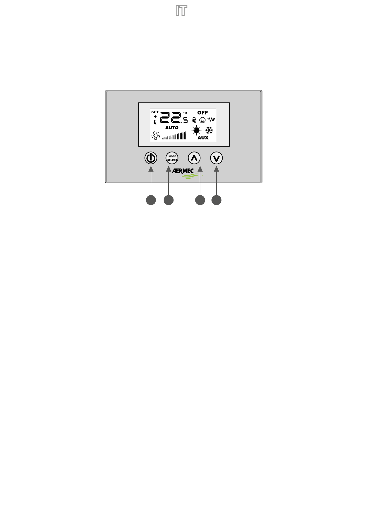
1. Interfaccia utente ..........................................................................................................p.5
2. Applicazioni del VMF-E4X...........................................................................................p.6
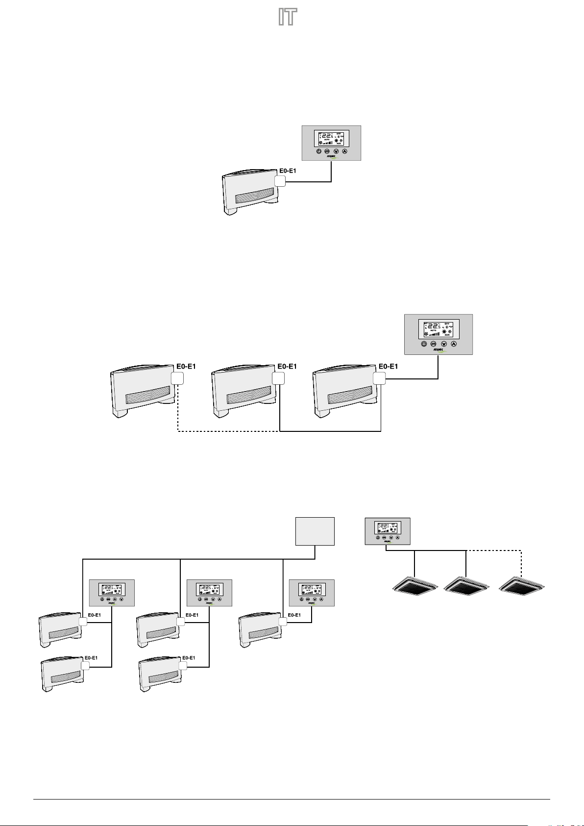
Applicazione stand alone.................................................................................................................p.6
Applicazione controllo di zona......................................................................................................p.6
Applicazione impianto centralizzato...........................................................................................p.6
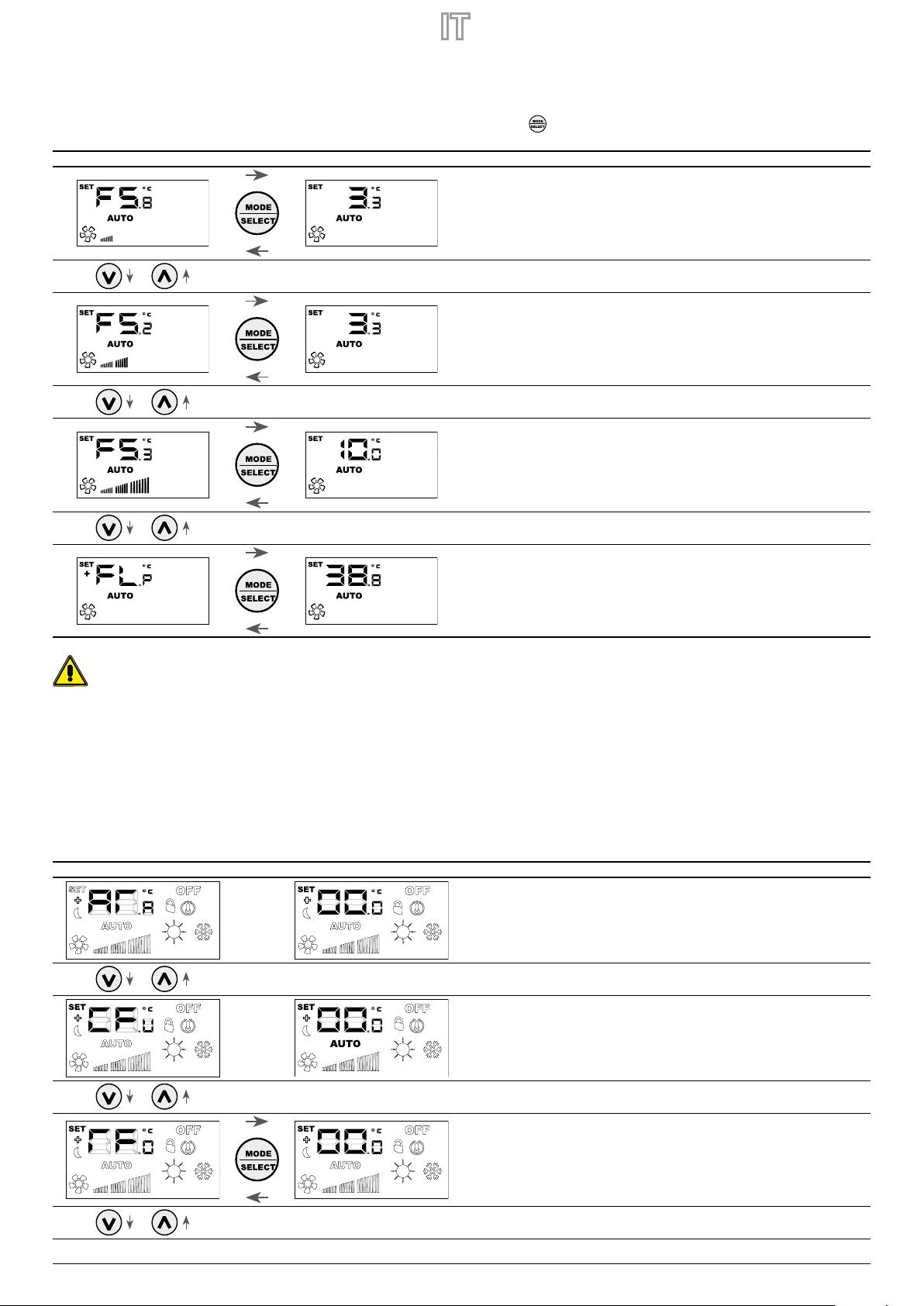
3. Procedura cambio set di temperatura...................................................................p.7
4. Procedura cambio della modalità di funzionamento.......................................p.7
5. Modica parametri utente.........................................................................................p.8
6. Modica parametri di visualizzazione....................................................................p.8
7. Scelta della sonda di temperatura...........................................................................p.9
8. Visualizzazioni del pannello.................................................................................... p.10
9. Indirizzamento dei ventilconvettori .................................................................... p.10
10. Visualizzazione degli indirizzi dei ventilconvettori ........................................ p.10
11. Visualizzazione degli allarmi................................................................................... p.11
12. Visualizzazione di particolari condizioni di funzionamento....................... p.11
TABLE OF CONTENTS EN
1. User interface ....................................................................................................... p.12
2. Application of the VMF-E4X ............................................................................ p.13
Stand alone application........................................................................................................p.13
Area control application........................................................................................................p.13
Centralised plant application..............................................................................................p.13
3. Temperature set change procedure............................................................. p.14
4. Functioning mode change procedure ........................................................ p.14
5. Change to user parameters............................................................................. p.15
6. Change visualization parameters.................................................................. p.15
7. Choice of temperature probe......................................................................... p.16
8. Panel displays....................................................................................................... p.17
9. Fan coils addressing........................................................................................... p.17
10. Fan coils address display.................................................................................. p.17
11. Alarms display...................................................................................................... p.18
12. Specic functioning conditions display...................................................... p.18
TABLE DES MATIÈRES FR
1. Interface utilisateur ............................................................................................................ p.19
2. Applications du VMF-E4X................................................................................................. p.20
Application individuel............................................................................................................................. p.20
Application controle de zone ............................................................................................................... p.20
Application installation centralisee.................................................................................................... p.20
3. Procédure de modication de la valeur de température ..................................... p.21
4. Procédure de modication de la modalité de fonctionnement........................ p.21
5. Modication des paramètres utilisateur.....................................................................p.22
6. Paramètres de visualisation de changement............................................................ p.22
7. Choix de la sonde de température............................................................................... p.23
8. Achages du panneau..................................................................................................... p.24
9. Adressage des ventilo-convecteurs............................................................................. p.24
10. Achage des adresses des ventilo-convecteurs..................................................... p.24
11. Achage des alarmes....................................................................................................... p.25
12. Achage des conditions particulières de fonctionnement................................ p.25
INHALTSVERZEICHNIS DE
1. Benutzerschnittstelle.................................................................................................................. S.26
2. Applications du VMF-E4X.......................................................................................................... S.27
Anwendung stand-alone...................................................................................................................................S.27
Anwendung bereichssteuerung .....................................................................................................................S.27
Anwendung Zentral Gesteuerte Anlage......................................................................................................S.27
3. Verfahren zum Ändern des Temperatur-Sollwerts........................................................... S.28
4. Vorgehensweise zum Ändern der Betriebsart................................................................... S.28
5. Änderung der Benutzerparameter ........................................................................................ S.29
6. Änderung der Visualisierungsparameter............................................................................. S.29
7. Auswahl Des Temperaturfühlers............................................................................................. S.30
8. Anzeigen der Bedientafel.......................................................................................................... S.31
9. Adressierung der Gebläsekonvektoren................................................................................ S.31
10. Anzeige der Adressen der Gebläsekonvektoren............................................................... S.31
11. Alarmanzeige................................................................................................................................. S.32
12. Anzeige von besonderen Betriebsbedingungen............................................................. S.32
ÍNDICE ES
1. Interfaz de usuario ..................................................................................................... p.33
2. Aplicaciones del VMF-E4X....................................................................................... p.34
Aplicación stand alone................................................................................................................... p.34
Aplicación control de zona........................................................................................................... p.34
Aplicación sistema centralizad.................................................................................................... p.34
3. Procedimiento de cambio de set de temperatura ......................................... p.35
4. Procedimiento de cambio del modo de funcionamiento........................... p.35
5. Modicar parámetros del usuario ........................................................................ p.36
6. Cambiar los parámetros de visualización.......................................................... p.36
7. Selección de la sonda de temperatura............................................................... p.37
8. Visualizaciones del panel......................................................................................... p.38
9. Dirección de los ventiloconvectores ................................................................... p.38
10. Visualización de las direcciones de los ventiloconvectores........................ p.38
11. Visualización de las alarmas.................................................................................... p.39
12. Visualización de condiciones especiales de funcionamiento .................... p.39

23/03 – 6795769_04 5
1 INTERFACCIA UTENTE
Nuova interfaccia utente digitale da parete, con tastiera touch, adatta alla gestione di fancoil di ogni tipo. Si caratterizza per il design accattivante e lo spessore di soli 11 mm. Tale
interfaccia ricopre una scatola ad incasso 503. La caratteristiche principali sono:
— Display LCD
— Possibilità di gestire fancoil con tecnologia ad inverter. In tal caso è possibile variare la velocità del ventilatore, nel modo di funzionamento manuale, secondo una scala di 20 posi-
zioni visualizzabili tramite barre graduate
— Visualizzazione allarmi
— Visualizzazione del set, della stagione e della temperatura ambiente letta
1 Tasto ON/OFF
2 Tasto cambio modo e conferma dato
3 Tasto incrementa dato
4 Tasto decrementa dato
1 42 3

6 23/03 – 6795769_04
2 APPLICAZIONI DEL VMF-E4X
APPLICAZIONE STAND ALONE
L’applicazione più semplice per l’utilizzo del VMF-E4X prevede un solo fancoil pilotato da un singolo pannello, tale collegamento è di tipo ModBus TTL e la sua massima lunghezza può
essere di 30 metri.
VMF-E4X
APPLICAZIONE CONTROLLO DI ZONA
Per creare un controllo di zona utilizzando il VMF-E4X è necessario che i vari fancoils, che compongono la zona, siano tutti dotati di scheda E0/E1/E19/E19I e che a loro volta le schede
siano collegate tra loro; il VMF-E4X sarà collegato all’unità MASTER, le cui impostazioni verranno replicate su tutte le restanti unità SLAVE. Il collegamento delVMF-E4X è di tipo ModBus
TTL e la sua massima lunghezza può essere di 30 metri.
VMF-E4X
APPLICAZIONE IMPIANTO CENTRALIZZATO
Per creare un impianto centralizzato è necessario utilizzare il pannello evoluto VMF-E5 /VMF-E6; in questo caso l’uso del VMF-E4X si riduce al controllo di zona (in un impianto centraliz-
zato possono essere gestite no a 64 zone, tale gestione è richiesta al pannello centralizzatore E5 o E6.), per cui si può far riferimento alla descrizione precedente.
VMF-E4X
FCL master FCL slave #1 FCL slave #5
MODBUS TTL
VMF-E5/E6
VMF-E4XVMF-E4XVMF-E4X

23/03 – 6795769_04 7
3 PROCEDURA CAMBIO SET DI TEMPERATURA
Per impostare il set di temperatura dei fancoils nella zona gestita dal VMF-E4X, seguire le operazioni descritte in seguito:
— Durante il normale funzionamento, sul display (indicato come icona 1) viene visualizzata la temperatura ambiente.
— La pressione di uno dei due tasti ( ) o ( ), durante il normale funzionamento, porta il VMF-E4X nella modalità cambio set di temperatura
— Dopo la pressione dei tasti indicati precedentemente, il funzionamento passa dalla normale visualizzazione alla modalità cambio set; tale modalità è indicata dall’icona sul display
(2); quando questa icona è visualizzata, i numeri a anco non indicano più la temperatura ambiente, ma il set di temperatura impostato (o lo scostamento se l’impianto è centraliz-
zato). La pressione di uno dei due tasti ( ) o ( ) modica il set di temperatura impostato; mentre la pressione del tasto ( ) conferma il dato inserito.
12
ATTENZIONE: per le applicazioni “stand alone” e“controllo di zona”, i range impostabili per i set di lavoro sono:
Temp. max. (°C) Temp. min. (°C) Modalità di funzionamento
17.0 33.0 Freddo
12.0 28.0 Caldo
mentre, per quanto riguarda le applicazioni“impianto centralizzato”, il set visualizzato non è un valore assoluto ma uno scostamento relativo al dato imposto
nel sistema centralizzato; il range di tale scostamento è:
Temp. max. (°C) Temp. min. (°C) Modalità di funzionamento
-6 +6 Zona morta termostato 5°C
-3 +3 Zona morta termostato 2°C
4 PROCEDURA CAMBIO DELLA MODALITÀ DI FUNZIONAMENTO
Il VMF-E4X gestisce 5 diverse modalità di funzionamento:
— AUTO: la velocità dei ventilatori è gestita automaticamente in base al set impostato ed alla temperatura ambiente rilevata;
— V1: la velocità dei ventilatori è impostata come“bassa velocità”;
— V2: la velocità dei ventilatori è impostata come“media velocità”;
— V3: la velocità dei ventilatori è impostata come“alta velocità”;
— AUX: la velocità dei ventilatori è gestita automaticamente in base al set impostato ed alla temperatura ambiente rilevata; inoltre vengono gestiti eventuali accessori pilotabili dal
termostato (Es: resistenza elettrica integrativa).
Per scorrere tra le varie modalità di funzionamento premere il tasto ( ).

8 23/03 – 6795769_04
5 MODIFICA PARAMETRI UTENTE
Il pannello VMF-E4X presenta dei parametri deniti“Utente”che servono per selezionare la velocità dei ventilconvettori inverter quando quest’ultimi lavorano nelle modalità V1, V2, V3
e per impostare la posizione dei deettori per i ventilconvettori FCL con griglia GLFM.
Per poter accedere all’area menù“Utente”si deve tenere premuto per circa 5 secondi il tasto Mode/Select ( ).
Simbolo del parametro Cambio valore parametro
Fan Speed in modalità V1 (valore intervallo 5÷34%)
Fan Speed in modalità V2 (valore intervallo 33÷67%)
Fan Speed in modalità V3 (valore intervallo 67÷100%)
Posizione deettori (valore intervallo 0÷101%). Con valore 101 si attiva la modalità SWING.
Attenzione: Con il parametro FLP (Flaps position) si può selezionare la posizione dei deettori presenti nella griglia motorizzata GLFxxM, se il valore è compreso tra 0 e 100%
il parametro FLP rappresenta la posizione del deettore, se il valore selezionato è 101 si attiva invece la modalità di funzionamento SWING (movimentazione continua dei 4
deettori presenti nella griglia).
6 MODIFICA PARAMETRI DI VISUALIZZAZIONE
Il pannello VMF-E4X per poter soddisfare le esigenze della building automation prevede dei parametri inerenti alla possibilità di visualizzare l’eettivo setpoint e di modicare la
visualizzazione dello stato di funzionamento se il termostato a cui è collegato è sottoposto a comandi di forzatura da parte di un BMS esterno. Inoltre in questo sotto menù si trova il
parametro per la selezione dell’unità di misura della temperatura: °C / °F. Per poter accedere a questo sottomenù è necessario premere simultaneamente per qualche secondo il tasto
UP e DOWN (vedi tabella sottostante).
Simbolo del parametro Cambio valore parametro
Parametro per la correzione da apportare alla lettura sonda: -5°C ÷ 5°C
Selezione dell'unità di temperatura:
0 = °C
1 = °F
Abilitazione a modicare la visualizzazione del modo di funzionamento da supervisione:
0 = non abilitato
1 = abilitato

23/03 – 6795769_04 9
Simbolo del parametro Cambio valore parametro
Modo di visualizzazione del setpoint se presente un supervisore esterno:
0 = scostamento
1 = eettivo setpoint
7 SCELTA DELLA SONDA DI TEMPERATURA
Il pannello VMF-E4X permette all’utente di selezionare, tramite parametro software, la sonda di temperatura di riferimento per la regolazione del termostato E0/E1/E19/E19I.
Posizione delle sonde di temperatura
Nella gura è rappresentato un esempio di installazione in cui si ha un fancoil (master) controllato dal pannello VMF-E4X. In questo caso, le sonde che rilevano la temperatura ambiente
sono posizionate a bordo del pannellino e del ventilconvettore.
Per la regolazione della temperatura d’ambiente da parte del termostato è possibile scegliere una tra le tre seguenti congurazioni:
Congurazione Descrizione
Regolazione con sonda presente a bordo del pannello
Regolazione con sonda presente a bordo del fancoil
Regolazione con valore mediato dalla lettura delle due sonde
Regolazione con sonda presente a bordo del pannello senza ltraggio software
Regolazione con valore mediato tra sonda presente a bordo fancoil e valore della sonda senza ltraggio software
Per selezionare la congurazione idonea alla specica installazione è suciente eseguire le tre operazioni seguenti:
1. Tenere premuto il tasto ( ) per 5 secondi, passando alla modalità“scelta del tipo di regolazione”;
2. Con i tasti ( ) e ( ) modicare il tipo di regolazione;
3. Premere il tasto ( ) per confermare la scelta e tornare alla modalità“controllo d’ambiente”.
Nota: per l’utilizzo del controllo di zona e abilitazione del circolatore da parte del sistema centralizzato (BMS o VMF-E5 o VMF-E6) questo parametro deve essere impostato in modalità C1
o C3.

10 23/03 – 6795769_04
Per selezionare la congurazione idonea alla specica installazione è suciente eseguire le tre operazioni rappresentate nella gura sottostante:
Step 1: Premere il pulsante per passare in modalità cambio tipo di gestione della sonda aria
Step 2: Con i pulsanti o modicare il modo di gestione della sonda aria
Step 3: Premere il pulsante o attendere 10 secondi per ritornare alla schermata principale
8 VISUALIZZAZIONI DEL PANNELLO
Il pannello VMF-E4X, come evidenziato nel paragrafo delle applicazioni, può essere usato in installazioni di diverse complessità e quindi si ha l’esigenza di prevedere delle visualizzazioni
speciche per individuare eventuali anomalie o particolari condizioni di funzionamento dell’impianto.
9 INDIRIZZAMENTO DEI VENTILCONVETTORI
Come visto nell’applicazione“Impianto centralizzato”il pannello VMF-E4X può essere collegato ad un ventilconvettore“master”di una zona. Quest’ultimo per comunicare con il sistema
di supervisione necessita, in fase di installazione, di essere indirizzato in modo univoco. Questo processo di “indirizzamento”è svolto dal sistema di supervisione (BMS/VMF) e la sua
esecuzione è individuabile dall’utente attraverso la visualizzazione in cui si evidenzia il lampeggio della stringa“Add”:
Per associare un indirizzo al termostato al sistema di supervisione è suciente premere il tasto (accertarsi prima che il termostato sia in ON). La conferma del buon esito del
procedimento è data dal cambio di visualizzazione del pannello VMF-E4X che prevede l’alternanza della stringa Add con il valore decimale dell’indirizzo appena associato al termostato.
La ne del procedimento di“auto indirizzamento”è dettata dal sistema di supervisione, quando questa avviene il pannello VMF-E4X si riporta al normale funzionamento visualizzando
la schermata principale.
10 VISUALIZZAZIONE DEGLI INDIRIZZI DEI VENTILCONVETTORI
Come abbiamo visto in precedenza, in un impianto centralizzato ogni termostato“master” ha un determinato indirizzo che lo specica nella comunicazione.
In certe situazioni di diagnostica dell’intero impianto è necessario vericare tale valore di indirizzo e ciò può essere forzato tramite un comando inviato dal sistema di supervisione (BMS/
VMF). Con il pannello VMF-E4X la lettura dell’indirizzo del ventilconvettore è eettuata come indicato dalla gura successiva.
L’arresto di tale visualizzazione è richiesto sempre al sistema di supervisione.

23/03 – 6795769_04 11
11 VISUALIZZAZIONE DEGLI ALLARMI
Il VMF-E4X prevede la visualizzazione di alcune anomalie che possono insorgere nel ventilconvettore; questi malfunzionamenti sono indicati tramite una stringa “AL” seguita da un
codice, come indicato nell’esempio successivo:
I possibili codici di allarme sono:
Codice Errore Signicato
AL1Assenza di comunicazione tra interfaccia VMF-E4X e termostato E0/E1
AL2Allarme o guasto sull’inverter
AL3Guasto sonda ambiente presente a bordo del VMF-E4X
Nota: In caso di guasto alla sonda ambiente del VMF-E4X, si abilita automaticamente il funzionamento della sonda presente a bordo fancoil.
12 VISUALIZZAZIONE DI PARTICOLARI CONDIZIONI DI FUNZIONAMENTO
Di seguito si riporta una tabella che descrive brevemente alcune combinazioni di visualizzazioni utilizzate per rappresentare particolari condizioni di utilizzo:
Simbolo Stato simbolo Signicato
ON Termostato disabilitato
ON Modo di funzionamento del termostato forzato da supervisore
ON Attiva la modalità SLEEP (per fancoils che montano il termostato E1 ed hanno il changeover lato acqua)
ON Richiesta da termostato
// Funzione non disponibile
ON Funzionamento a caldo da termostato
ON Funzionamento a freddo da termostato
ON LAMPEGGIANTE Funzionamento a caldo da termostato con acqua insuciente (acqua fredda)
LAMPEGGIANTE ON Funzionamento a freddo da termostato con acqua insuciente (acqua calda)
LAMPEGGIANTE Funzionamento antigelo
LAMPEGGIANTE LAMPEGGIANTE Funzionamento antigelo con acqua insuciente (acqua fredda)

12 23/03 – 6795769_04
1 USER INTERFACE
User interface developed for wall installation. New wall-hung digital user interface, with touch keyboard, suitable to manage fancoils of all types. It is characterised for its
captivating design and thickness of only 11 mm. This interface covers a 503 recess box. The main features are:
— LCD display
— Possibility of managing fancoils with inverter technology. In this case, fan speed can be varied, in manual functioning mode, according to a scale of 20 positions viewable
via graduated bars
— Alarms display
— Displaying the set, the season and the environment temperature read
1 ON/OFF button
2 Mode change and conrm data button
3 Data increase key
4 Data decrease key
1 42 3

23/03 – 6795769_04 13
2 APPLICATION OF THE VMF-E4X
STAND ALONE APPLICATION
The most simple application for the use of the VMF-E4X, envisions just one fancoil piloted by an individual panel. This connection is the ModBus TTL type and its maximum
length can be 30 metres.
VMF-E4X
AREA CONTROL APPLICATION
To create an area control using the VMF-E4X, it is necessary that the various fancoils that make up the area are all supplied with E0/E1/E19/E19I boards, which are connected
to each other. TheVMF-E4X will be connected to the MASTER unit, whose settings will be repeated on all of the remaining SLAVE units. The VMF-E4X connection is the ModBus
TTL type and its maximum length can be 30 metres.
VMF-E4X
CENTRALISED PLANT APPLICATION
To create a centralised system, the developed VMF-E5 / VMF-E6 panel must be used. In this case the use of the VMF-E4X is reduced to area control (in a centralised system up
to 64 areas can be managed.This management is delegated to the E5/E6 developed panel), therefore reference can be made to the previous description.
VMF-E4X
FCL master FCL slave #1 FCL slave #5
MODBUS TTL
VMF-E5/E6
VMF-E4XVMF-E4XVMF-E4X

14 23/03 – 6795769_04
3 TEMPERATURE SET CHANGE PROCEDURE
To set the temperature of the fancoils in the area managed by the VMF-E4X, follow the operations described below:
— During normal functioning, the display shows the environment temperature (indicated as icon 1).
— Pressing one of the two keys ( ) or ( ) during normal functioning, takes the VMF-E4X into the temperature set change mode.
— When the previously indicated keys have been pressed, functioning passes from normal display to set change mode. This mode is indicated by the icon on the display
(2). When this icon is displayed, the numbers at the side no longer indicate the room temperature, but the set temperature set (or the oset if the system is centralised).
Pressing one of the two ( ) or ( ) keys modies the set temperature set; while pressing the ( ) key, conrms the data introduced.
12
WARNING: for the“stand alone”and “area control”, applications, the ranges that can be set for the work set are:
Max. temp. (°C) Min temp. (°C) Operating mode
17.0 33.0 Cooling
12.0 28.0 Heating
while regarding the“centralised system”applications, the displayed set is not an absolute value but an oset relative to the data set in the centralised
system. The range of this oset is:
Max. temp. (°C) Min temp. (°C) Operating mode
-6 +6 Thermostat 5°C dead zone
-3 +3 Thermostat 2°C dead zone
4 FUNCTIONING MODE CHANGE PROCEDURE
The VMF-E4X manages 5 dierent functioning modes:
— AUTO: the fans speed is managed automatically on the basis of the set and the room temperature detected;
— V1: the fans speed is set as“low speed”;
— V2: the fans speed is set as“average speed”;
— V3: the fans speed is set as“high-speed”;
— AUX: the speed of the fans is managed automatically on the basis of the set and the room temperature detected. Moreover, any pilotable accessories are managed by the
thermostat (e.g.: integrative electric resistance).
To scroll through the various functioning modes press the ( ).

23/03 – 6795769_04 15
5 CHANGE TO USER PARAMETERS
The VMF-E4X panel has parameters dened as "User" that are used to select the speed of the inverter fan coils when the latter operates in modes V1, V2, V3 and to set the
position of the aps for FCL fan coils with GLFM grille.
To access the "User" menu area, press the Mode/Select key ( ) for about 5 seconds.
Parameter symbol Change parameter value
Fan Speed in mode V1 (range value 5÷34 %)
Fan Speed in mode V2 (range value 33÷67%)
Fan Speed in mode V3 (range value 67÷100 %)
Flaps position (range value 0 ÷ 101 %). With value 101, SWING mode is activated.
Attention: The FLP (Flaps position) parameter allows to select the position of the aps in the motorized GLFxxM grille, if the value is between 0 and 100% the FLP
parameter represents the position of the deector, if the value selected is 101 it activates the SWING operating mode (continuous movement of the 4 deectors in
the grille).
6 CHANGE VISUALIZATION PARAMETERS
The VMF-E4X panel, in order to meet the needs of the building automation, includes parameters relating to the possibility of displaying the actual setpoint and modifying the
display of the operating status if the thermostat to which it is connected is subject to force commands by a BMS. external. In addition to this sub-menu there is the parameter
for selecting the temparature measuring unit: ° C / ° F. To access this submenu, press the UP and DOWN keys simultaneously (see table below) for a few seconds.
Parameter symbol Change parameter value
Parameter for probe reading correction: -5°C ÷ 5°C
Temperature unit selection:
0 = °C
1 = °F
Enabling to change the display of the supervision operating mode:
0 = not enabled
1 = enabled

16 23/03 – 6795769_04
Parameter symbol Change parameter value
Display mode of the set point if an external supervisor is present:
0 = deviation
1 = actual setpoint
7 CHOICE OF TEMPERATURE PROBE
The VMF-E4X panel allows the user to select, via a software parameter, the reference temperature probe for the adjustment of the E0/E1/E19/E19I thermostat.
Position of temperature probes
The gure shows an example of installation in which there is a fan coil (master) controlled by the VMF-E4X panel. In this case, the probes that detect the room temperature are
positioned on the panel and the fan coil.
To adjust the room temperature by means of the thermostat, one of the following three congurations can be selected:
Conguration Description
Regulation with probe present on panel
Regulation with probe present on fancoil
Regulation with average value between the two probes
Adjustment with probe on board panel without ltering software
Adjustment with average value between the probe on board fan coils and value panel probe without ltering software
To select the suitable conguration for the specic installation, just perform the three following operations:
1. Hold the ( ) key down for 5 seconds, passing to the“choice of the type of regulation”mode;
2. Use the ( ) and ( ) keys to modify the type of regulation;
3. Press the key ( ) to conrm the choice and go back to the“environment control”mode.
Note: to use the area control and enabling of the pump by the centralised system (BMS/VMF-E5/VMF-E6) this parameter must be set in C1 or C3 mode.

23/03 – 6795769_04 17
To select the conguration suitable for the specic installation, simply perform the three operations shown in the gure below:
Step 1: Press the or button to switch to the air probe management type change mode
Step 2: With the buttons or change the air probe management mode
Step 3: Press the button or wait 10 seconds to return to the main screen
8 PANEL DISPLAYS
The VMF-E4X panel, as highlighted in the paragraph of the applications, can be used in installations of dierent complexity and therefore it is necessary to provide specic
displays to identify any anomalies or particular operating conditions of the system.
9 FAN COILS ADDRESSING
As seen in the "Centralized system" application, the VMF-E4X panel can be connected to a "master" fan coil of a zone. The latter, in order to communicate with the supervision
system, needs to be uniquely addressed during installation. This "addressing" process is carried out by the supervision system (BMS/VMF) and its execution can be identied
by the user through the display in which the ashing of the string "Add" is highlighted:
To associate an address to the thermostat from the supervision system, simply press the key (make sure the thermostat is ON before hand). Conrmation that the outcome
of the procedure was successful is given by the change in display of panel VMF-E4X which shows the alternation of the Add string with the decimal value of the address just
associated to the thermostat.
The end of the "auto-addressing" procedure is dictated by the supervision system, therefore, when this occurs panel VMF-E4X returns to normal operation displaying the main
screen.
10 FAN COILS ADDRESS DISPLAY
As seen previously, in a centralized system every "master" thermostat has a specic address that species it in communication.
In certain diagnostic situations of the entire system it is necessary to check this address value that can be forced by means of a command sent by the supervision system (BMS/
VMF). With the VMF-E4X panel, the fan coil address is read as shown in the gure below.
The closure of this display is always entrusted to the supervision system.

18 23/03 – 6795769_04
11 ALARMS DISPLAY
The VMF-E4X envisions the display of some anomalies that can arise in the fancoil. These malfunctions are indicated via a string “AL” followed by a code, as indicated in the
next example:
The possible alarm codes are:
Error code Meaning
AL1No communication between interface VMF-E4X and thermostat E0/E1
AL2Alarm of fault on the inverter
AL3Room probe fault present on the VMF-E4X
Note: If the VMF-E4X room probe breaks, functioning of the probe on the fancoil is automatically enabled.
12 SPECIFIC FUNCTIONING CONDITIONS DISPLAY
Below nd a table that briey describes some display combinations used to represent the particular conditions of use:
Symbol Symbol status Meaning
ON Thermostat disabled
ON Thermostat operating mode forced by supervisor
ON Activates the SLEEP mode (for fancoils that have thermostat E1 and have water side changeover)
ON Thermostat request
// Function not available
ON Heating functioning from thermostat
ON Cooling functioning from thermostat
ON BLINK Heat mode functioning from thermostat with insucient water (cold water)
BLINK ON Cooling mode functioning from thermostat with insucient water (hot water)
BLINK Anti-freeze functioning
BLINK BLINK Thermostat anti-freeze functioning with insucient water (cold water)

23/03 – 6795769_04 19
1 INTERFACE UTILISATEUR
Nouvelle interface utilisateur numérique murale, avec clavier tactile, adapté pour gérer les fancoils de tout type. Elle se caractérise par un design irrésistible et par une épaisseur de seulement 11
mm. Cette interface recouvre un boîtier encastré 503. Ses caractéristiques principales sont:
— Écran LCD
— Possibilité de gérer les fancoils avec une technologie à inverter. Dans ce cas, il est possible de faire varier la vitesse du ventilateur, en mode de fonctionnement manuel, selon une échelle de
20 positions, achables au moyen d’une barre graduée
— Achage alarmes
— Achage du point de consigne, de la saison et de la température ambiante lue
1 Touche ON/OFF
2 Touche de changement de mode et de conrmation des données
3 Touche d’augmentation de la donnée
4 Touche de diminution de la donnée
1 42 3

20 23/03 – 6795769_04
2 APPLICATIONS DU VMF-E4X
APPLICATION INDIVIDUEL
L’application la plus simple pour l’utilisation de VMF-E4X prévoit un seul fancoil piloté par un seul panneau, ce raccordement est de type ModBus TTL, et sa longueur maximale peut être de 30
mètres.
VMF-E4X
APPLICATION CONTROLE DE ZONE
Pour créer un contrôle de zone en utilisant le VMF-E4X, les divers fancoils qui composent la zone doivent tous être dotés de cartes E0/E1/E19/E19I qui sont connectées entre-elles; le VMF-E4X
sera connecté à l’unité MAITRE dont les congurations devront être répliquées sur toutes les unités ESCLAVE. Le raccordement du VMF-E4X est de type ModBus TTL, et sa longueur maximum
peut être de 30 mètres.
VMF-E4X
APPLICATION INSTALLATION CENTRALISEE
Pour créer une installation centralisée, il convient d’utiliser le panneau évolué VMF-E5 / VMF-E6; dans ce cas, l’utilisation du VMF-E4X se réduit au contrôle de zone (dans une installation centrali-
sée, il permet de gérer jusqu’à 64 zones, et cette gestion est assurée par le panneau évolué E5/E6), et l’on peut donc se référer à la description précédente.
VMF-E4X
FCL master FCL slave #1 FCL slave #5
MODBUS TTL
VMF-E5/E6
VMF-E4XVMF-E4XVMF-E4X
Table of contents
Languages:
Other AERMEC Recording Equipment manuals