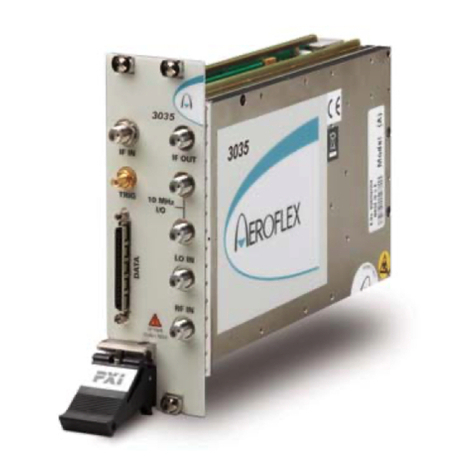
Aeroflex 3060 Series User manual

-~
ARTISAN
®
~I
TECHNOLOGY
GROUP
Your definitive source
for
quality
pre-owned
equipment.
Artisan Technology
Group
Full-service,
independent
repair
center
with
experienced
engineers
and
technicians
on staff.
We
buy
your
excess,
underutilized,
and
idle
equipment
along
with
credit
for
buybacks
and
trade-ins
.
Custom
engineering
so
your
equipment
works
exactly as
you
specify.
•
Critical
and
expedited
services
•
Leasing
/
Rentals/
Demos
• In
stock/
Ready-to-ship
•
!TAR-certified
secure
asset
solutions
Expert
team
ITrust
guarantee
I
100%
satisfaction
All
tr
ademarks,
br
a
nd
names, a
nd
br
a
nd
s a
pp
earing here
in
are
th
e property of
th
e
ir
r
es
pecti
ve
ow
ner
s.
Visit our website - Click HERE

3060, 3061, 3065, 3065A (3060 Series)
RF Combiner PXI Modules
User Manual
Document no. 46892/762
Issue 8
26 July 2011

PREFACE
2
About this manual
This manual explains how to set up and configure an Aeroflex 3060, 3061 or 3065 RF
combiner PXI module. Where necessary, it refers you to the appropriate installation
documents that are supplied with the module.
Please note: this manual applies only when the instrument is used with the supplied software.
This manual provides information about how to configure the module as a stand-alone device.
However, one of the advantages of Aeroflex 3000 Series PXI modules is their ability to form
versatile test instruments, when used with other such modules and running 3000 Series
application software.
© Aeroflex Ltd. 2011
No part of this document may be reproduced or transmitted in any form
or by any means, electronic or mechanical, including photocopying,
or recorded by any information storage or retrieval system,
without permission in writing by Aeroflex Ltd.
(hereafter referred to throughout the document as ‘Aeroflex’).

PREFACE
3
Intended audience
Engineers who require to interface various PXI RF test resources with the item(s) under test.
This manual is intended for first-time users, to provide familiarity with basic operation.
Programming is not covered in this document but is documented fully in the help files that
accompany the drivers and associated software on the CD-ROM.
Driver version
This PXI RF module is designed to be used with the latest software driver version supplied on
the Aeroflex 3000 Series PXI Modules CD-ROM, part no. 46886/028. Operation with earlier
versions of driver software may not be supported.

PREFACE
4
Associated documentation
The following documentation covers specific aspects of this equipment:
If you want to… Refer to…
Find information about soft front panels,
drivers, application software, data
sheets, installation, getting started and
user manuals for this and other modules
in the 3000 Series
PXI Modules CD-ROM
Part no. 46886/028
Supplied with the module
Install modules into a rack, interconnect
them, power up and install drivers 3000 Series PXI Modules Common Installation Guide
Part no. 46892/663
On the CD-ROM and at www.aeroflex.com/
Set up a populated chassis ready for use 3000 Series PXI Modules Installation Guide for Chassis
Part no. 46892/667
On the CD-ROM and at www.aeroflex.com/
Set up and use the universal PXI
application for system configuration and
operation
PXI Studio User Guide
Part no: 46892/809
On the CD-ROM and at www.aeroflex.com/

PREFACE
5
Preface
The PXI concept
VXI and GPIB systems meet the specific needs of instrumentation users but are often too
large and expensive for mainstream applications. PC-based instrumentation may cost less but
cannot meet the environmental and operational requirements of many systems.
PXI (PCI Extensions for Instrumentation) is based on CompactPCI, itself based on the PCI
standard. PCI was designed for desktop machines but CompactPCI was designed for
industrial applications, and features a rugged Eurocard format with easy insertion and
removal. PXI adds to the CompactPCI specification by defining system-level specifications
for timing, synchronization, cooling, environmental testing, and software. While PXI extends
CompactPCI, it also maintains complete interoperability so that you can use any CompactPCI-
compliant product in a PXI system and vice versa. PXI also makes use of Windows software,
VXI timing and triggering, and VXIplug&play instrument drivers to provide powerful and
affordable systems.
PXI Express now integrates PCI Express into PXI, providing up to 6 Gbyte/s backplane
bandwidth and up to 2 Gbyte/s slot bandwidth. PXI Express maintains backwards
compatibility with PXI, providing software compatibility and hardware compatibility with
hybrid slots and hybrid systems.
Hybrid slot compatibility
PXI chassis that provide hybrid slots can accept both PXI Express modules and hybrid-
compatible PXI modules. Hybrid-compatible PXI modules have a ‘missing’ section of
connector (see Fig. 1), which allows them to be inserted into both hybrid slots and standard
PXI-1 slots.
Because of the reduced connectivity of Aeroflex hybrid-compatible PXI modules, the PXI
parallel local bus LBL[0]–[12] disappears, to be replaced by the serial connection LBL[6],
which is typically used to provide list addresses to a 3010 Series RF Synthesizer.

PREFACE
6
Fig. 1 Standard PXI 1-slot connector (L) and hybrid-compatible PXI connector (R)
This table shows which Aeroflex PXI combiner modules fit only in a standard 1-slot, and
which fit in both hybrid-compatible and standard slots:
3060 Standard PXI 1-slot
3061 Hybrid-compatible and standard PXI 1-slot
3065 Standard PXI 1-slot
3065A Standard PXI 1-slot
®is a registered trademark of Aeroflex International Inc. in the US
PXI™ is a registered trademark of the PXI Systems Alliance
Windows™, Windows XP™ and Windows NT™ are trademarks of Microsoft Corporation

7
GENERAL INFORMATION
Introduction
This is the user manual for the 3060, 3061 and 3065 RF combiner PXI modules, which are
referred to generically in this document as ‘3060 Series’.
These combiner PXI modules operate over the following frequency ranges:
3060 250 MHz to 2.7 GHz
3061 250 MHz to 2.7 GHz
3065 250 MHz to 6 GHz (usable to 70 MHz)
3065A 250 MHz to 6 GHz (usable to 70 MHz)
and the following peak power level ranges:
A, B, C D Σ
3060 24 dBm 24 dBm n/a 27 dBm, 3 V dc
3061 24 dBm n/a n/a 30 dBm, 40 V dc
33 dBm, m:s = 1:1 where m = <0.5 ms
3065 24 dBm 24 dBm 24 dBm 27 dBm, 3 V dc
30 dBm, m:s = 1:8 where m = <0.5 ms
3065A 24 dBm 24 dBm 24 dBm 30 dBm, 3 V dc
33 dBm, m:s = 1:8 where m = <0.5 ms
These high-performance modules feature integrated high speed RF switching and a high
isolation RF power combiner/splitter in a 3U high single-slot PXI module.
These modules are intended for use in RF test systems with the 3020 Series digital RF signal
generator and 3030 Series RF digitizer. Together, these modules enable compact, high
performance modular RF test systems to be developed.

GENERAL INFORMATION
8
3060 Series combiners store their own path loss calibration data, which can be accessed via
software calls to the driver.
•Combiners provide a single output from any combination of input ports. Each port is bi-
directional, allowing many system configurations. Port D (3065/3065A only) allows for a
second output or input channel, or for testing of multifunction mobile telephones that
support non-cellular functions.
•Combiners provide direct RF switched connection between input ports to enable
automated test system calibration.
•Possible combinations are:
3060
Combined output
A, B, C to SUM
Switched connection
A to B
C to B
Switched and combined
A to B and C to SUM
C to B and A to SUM

GENERAL INFORMATION
9
3061
Combined output
A, B to SUM 1, 2 or 3
Switched connection
A to B

GENERAL INFORMATION
10
3065
Combined output
A, B, C to SUM
Switched connection
A to B and C to D
A to D and C to B
Switched and combined
A to B and C to SUM
C to B and A to SUM
C to D and A, B to SUM
A to D and C, B to SUM

GENERAL INFORMATION
11
3065A
Combined output
A, B to SUM
Switched connection
A to B and C to D
A to D and C to B
Switched and combined
C to B and A to SUM
C to D and A, B to SUM
A to D and B to SUM
SUM
C6399
S
C
B
A
D
CONTROL
PCI
BUS
RF BLOCK
3065A
Applications
3060 Series combiners can be used in radio test applications such as transceiver testing, where
the combined port Σacts as a single-port duplex connection, one or two RF sources provide
TX stimulus inputs, and an RF signal analysis instrument connected to the third port measures
the DUT’s TX parameters. For testing cellular phones with additional functions such as FM
radio or DVB, port D (3065/3065A only) allows a second RF source to be routed to the unit
under test. The 3061 combiner allows up to three devices (or three interfaces on a single
device) to be connected to the summing port, thereby reducing handling and test time.

GENERAL INFORMATION
12
Software
A 3060 Series combiner is supplied with a VXI PNP driver and soft front panel, and a COM
object and a C interface DLL that provide similar functionality to the driver.
PXI Studio, also supplied with the module, configures your PXI modules as logical
instruments using an intuitive and powerful graphical interface1. PXI Studio provides
comprehensive signal generator, digitizer and spectrum analyzer applications, and optional
analysis plug-ins to suit specific communications systems.
RF Investigator, also supplied with the module, is an application that provides combined
operation of all Aeroflex 3000 Series modules from a single user interface, especially useful
for acceptance testing.
1PXI Studio does not currently support 3061.

GENERAL INFORMATION
13
Deliverable items
•3060 Series RF Signal Generator PXI module
•PXI Modules CD-ROM (part no. 46886/028), containing soft front panels, drivers,
application software, data sheets, installation guides, safety instructions, getting started
and user manuals for this and other modules in the 3000 Series
•3000 Series PXI Modules Safety Instructions: printed item, part no. 46882/882
•SMA connector cable: part no. 43139/738; 1 off for 3060/3065/3065A only
•SMA connector cable: part no. 43139/739; 2 off for 3060/3061/3065/3065A
•50 ohm termination SMA, part no. 23448/726, 1 off for 3060/3065/3065A only
•SMA connector saver: part no. 46885/224, 1 off for 3060/3065/3065A, 3 off for 3061.
Cleaning
Before commencing any cleaning, switch off the chassis and disconnect it from the supply.
You can wipe the front panel of the module using a soft cloth moistened in water, taking care
not to wet the connectors. Do not use aerosol or liquid solvent cleaners.
Putting into storage
If you put the module into storage, ensure that the following conditions are not exceeded:
Temperature range: −20 to 70°C (-4 to +158°F)
Humidity: 5 to 93%, non-condensing

GENERAL INFORMATION
14
Specifications
For the latest specifications, see the data sheet included on the CD-ROM (part no. 46886/028)
or go to the Aeroflex website.
All 3060 Series specifications are defined when used in conjunction with the driver software
supplied with the module.
Warm-up time
Allow at least twenty minutes for a module to warm up and meet its specifications fully after
booting.
Calibration and servicing
The recommended calibration interval is 24 months.
There are no user-serviceable parts in these modules. If any attention is needed, return the
module to your Aeroflex agent.

15
INSTALLATION
WARNING
Initial visual inspection
Refer to the 3000 Series Common Installation Guide part no. 46892/663 on the PXI Modules
CD-ROM, part no. 46886/028.
Handling precautions
Refer to the 3000 Series Common Installation Guide part no. 46892/663 on the PXI Modules
CD-ROM, part no. 46886/028.

INSTALLATION
16
Hardware installation
WARNING
Before installing the module into the chassis, check inside the chassis:
(a) that no foreign conductive bodies are present between pins on the backplane connectors
(b) that no pins on the backplane connectors are bent or damaged.
Installing the module into the PXI chassis
Refer to the 3000 Series Common Installation Guide part no. 46892/663 and Installation
Guide for Chassis part no. 46882/697 on the PXI Modules CD-ROM, part no. 46886/028.
These guides provide information such as specific precautions to take, positioning and fitting
the modules, making connections for the LO and the 10 MHz reference signal, installing
hardware drivers, and so on.

INSTALLATION
17
Connector care and maintenance
How to connect and torque an SMA connector
1 First, ensure that the mating halves of the connector are correctly aligned.
2 Next, engage the threads of the nut and tighten it by hand, ensuring that the mating
halves do not move relative to each other.
3 Then use a torque spanner to tighten the connector, in order to ensure consistent
matching and to avoid mechanical stress.
Torque settings for connectors are:
0.56 Nm test torque (development use, semi-permanent installations)
1 Nm final torque (permanent installations)
Never use pliers to tighten connectors.
Overtightening will cause damage!
Do not allow center pins to rotate!
Do not allow the center pins of connectors to rotate when you connect and remove cables.

INSTALLATION
18
Use a connector saver!
Use a connector saver (part no. 46885/224, supplied):
(a) on any connector where the cable is routinely connected and disconnected
(b) when the connector on the cable, or the cable end of the connector saver, has not been
gauged.
Torque to 1 Nm the end of the connector saver that connects to the module, and torque to
0.56 Nm the end that connects to the cable.
Maintenance
SMA
Clean connectors regularly, using a cotton bud dipped in isopropyl alcohol. Wipe within the
connector cavity, then use a dry cotton bud to finish off. Check for any deposits.
Do not use other cleaners, as they can cause damage to the plastic insulators within the
connectors.
Cap unused connectors.
PCI
Protect PCI connector pins by keeping modules in their original packing when not fitted in the
rack.

19
OPERATION
Front-panel connectors
1 ΣCombined output. SMA socket, 50 Ω.
2 A, B, C Individual inputs. SMA socket, 50 Ω.
C
B
A
S
3060
C5692
2
1
SPWRSPWR
A/B/C PWRA/B/C PWR
27dBm MAX27dBm MAX
17dBm MAX17dBm MAX
Fig. 2 3060 front panel
Maximum safe powers
Σport: +27 dBm, 3 V dc continuous
A, B, C ports: +24 dBm
This manual suits for next models
4
Table of contents
Other Aeroflex Control Unit manuals

