Seco SECO104-CX700M User manual
SECO104-CX700M
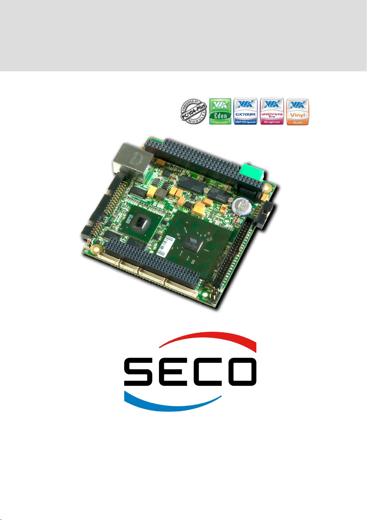
PC/104-Plus CPU with VIA EDEN®Ultra Low Voltage Technology
SECO104-CX700M
User Manual
StockCheck.com

SECO104-CX700M
User Manual - Rev. First Edition: 1.0 - Last Edition: 3.1 - Author: S.B. - Reviewed by G.M.
Copyright © 2011 SECO s.r.l.
SECO104-CX700M
pag. 2
REVISION HISTORY
Revision
Date
Note
Rif.
1.0
First release - Preliminary
GV
1.1
01/08/08
BIOS vers. 1.0
GV
1.2
01/10/08
Jumpers configuration, added connectors pinout
GV
1.3
10/11/08
SATA, PATA BIOS configuration
GV
1.4
12/11/08
CN2 pinout
GV
2.0
25/05/09
Structure reviewed.
Various descriptions added / changed.
BIOS section corrected and reviewed
SB
2.1
15/09/09
EDEN V4 LV 400MHz removed from list of CPU
SB
2.2
16/07/10
Battery paragraph updated (§ 3.3.2)
BIOS Section updated
SB
3.0
26/08/11
New graphical format
COM2 Serial port paragraph updated
SB
3.1
07/12/11
Technical features updated
Minor errors corrected
SB
All rights reserved. All information contained in this manual is confidential material and
property of SECO S.r.l.
Unauthorised use, duplication, modification or disclosure of the information to a third-party by any
means without prior consent of SECO S.r.l. is prohibited.
Every effort has been made to ensure the accuracy of this manual, however, SECO s.r.l. accepts
no responsibility for any inaccuracies, errors or omissions herein. SECO s.r.l. reserves the right to
change specifications without prior notice in order to supply the best product possible.
For more information on this and other SECO products, please visit our web-site at:
http://www.seco.com
and describing the current problem.
SECO Srl
Via Calamandrei 91
52100 Arezzo –ITALY
Ph: +39 0575 26979 - Fax: +39 0575 350210
http://www.seco.com
StockCheck.com

SECO104-CX700M
User Manual - Rev. First Edition: 1.0 - Last Edition: 3.1 - Author: S.B. - Reviewed by G.M.
Copyright © 2011 SECO s.r.l.
SECO104-CX700M
pag. 3
INDEX
Chapter 1 INTRODUCTION ...................................................................................................5
1.1 WARRANTY............................................................................................................................................ 6
1.2 INFORMATION AND ASSISTANCE .............................................................................................................. 7
1.3 RMA NUMBER REQUEST......................................................................................................................... 7
1.4 SAFETY ................................................................................................................................................. 8
1.5 ELECTROSTATIC DISCHARGES................................................................................................................ 8
1.6 ROHS COMPLIANCE ............................................................................................................................... 8
Chapter 2 OVERVIEW ...........................................................................................................9
2.1 INTRODUCTION..................................................................................................................................... 10
2.2 TECHNICAL SPECIFICATIONS................................................................................................................. 10
2.3 ELECTRICAL SPECIFICATIONS................................................................................................................ 11
2.3.1 Power Connector......................................................................................................................... 11
2.3.2 RTC Battery................................................................................................................................. 11
2.4 MECHANICAL SPECIFICATIONS .............................................................................................................. 12
2.5 BLOCK DIAGRAM.................................................................................................................................. 13
Chapter 3 CONNECTORS...................................................................................................14
3.1 CONNECTORS PLACEMENT ................................................................................................................... 15
3.2 CONNECTORS OVERVIEW ..................................................................................................................... 16
3.3 CONNECTORS DESCRIPTION ................................................................................................................. 17
3.3.1 FAN connector............................................................................................................................. 17
3.3.2 LVDS Channels Connectors........................................................................................................ 17
3.3.3 CRT Connector............................................................................................................................ 18
3.3.4 Fast Ethernet connector .............................................................................................................. 18
3.3.5 ISA PC/104 BUS Expansion connector....................................................................................... 18
3.3.6 PC104+ PCI BUS Expansion connector...................................................................................... 20
3.3.7 Parallel Port /Floppy Disk Connector........................................................................................... 22
3.3.8 USB Ports connector ................................................................................................................... 22
3.3.9 Utility Connector........................................................................................................................... 23
3.3.10 COM2 RS232/RS422/RS485 Serial Port Connector................................................................... 23
3.3.11 COM1 Serial Port Connector....................................................................................................... 24
3.3.12 Dual Audio Amplified connector................................................................................................... 24
3.3.13 Speaker L/R and MIC connector ................................................................................................. 25
3.3.14 SATA connector........................................................................................................................... 25
3.3.15 HDD EIDE connector................................................................................................................... 26
3.3.16 SO-DIMM DDR2 Connector ........................................................................................................ 27
3.3.17 Jumpers configuration ................................................................................................................. 27
Chapter 4 BIOS SETUP.......................................................................................................28
4.1 INTRODUCTION..................................................................................................................................... 29
4.2 BASIC CMOS CONFIGURATION............................................................................................................. 30
4.3 ADVANCED CMOS CONFIGURATION..................................................................................................... 32
4.3.1 Boot as fast as possible............................................................................................................... 32
4.3.2 Display setup message................................................................................................................ 32
4.3.3 Wait to ease setup entry.............................................................................................................. 32
4.3.4 Display tests behaviour................................................................................................................ 32
4.3.5 System configuration box ............................................................................................................ 32
4.3.6 Memory test tick........................................................................................................................... 32
4.3.7 Test Above 1 MB ......................................................................................................................... 33
4.3.8 Wait for F1 on error...................................................................................................................... 33
4.3.9 Ignore keyboard error .................................................................................................................. 33
4.3.10 Pointing device (Mouse) .............................................................................................................. 33
4.3.11 Show Graphic Logo ..................................................................................................................... 33
4.3.12 Internal video boot on .................................................................................................................. 33
4.3.13 External PCI video master........................................................................................................... 33
4.3.14 W.D.T time-out at boot................................................................................................................. 33
StockCheck.com

SECO104-CX700M
User Manual - Rev. First Edition: 1.0 - Last Edition: 3.1 - Author: S.B. - Reviewed by G.M.
Copyright © 2011 SECO s.r.l.
SECO104-CX700M
pag. 4
4.3.15 No zero extended RAM ............................................................................................................... 33
4.3.16 Seek Hard Drive at Boot.............................................................................................................. 33
4.3.17 Sec. to wait for HD reset.............................................................................................................. 33
4.3.18 First / Second / Third / Fourth boot device .................................................................................. 34
4.3.19 NumLock State at Boot................................................................................................................ 34
4.3.20 Typematic Programming.............................................................................................................. 34
4.3.21 Typematic Rate............................................................................................................................ 34
4.3.22 Typematic Rate Delay ................................................................................................................. 34
4.3.23 Flat Panel centering..................................................................................................................... 34
4.3.24 Enhanced BIOS loading .............................................................................................................. 34
4.3.25 USB Keyboard after boot............................................................................................................. 34
4.4 CHIPSET CONFIGURATION .................................................................................................................... 35
4.4.1 Internal COMA / COMB I/O ......................................................................................................... 35
4.4.2 Internal COMA/COMB IRQ.......................................................................................................... 35
4.4.3 Internal COMB Interface.............................................................................................................. 35
4.4.4 Parallel connected to ................................................................................................................... 36
4.4.5 Internal LPT ................................................................................................................................. 36
4.4.6 Internal LPT IRQ.......................................................................................................................... 36
4.4.7 Internal USB Port Enabled........................................................................................................... 36
4.4.8 PCI INTA / Video / IRQ................................................................................................................ 36
4.4.9 Internal Audio............................................................................................................................... 36
4.4.10 PCI INTB / audio IRQ .................................................................................................................. 36
4.4.11 Internal LAN................................................................................................................................. 36
4.4.12 PCI INTC / LAN IRQ.................................................................................................................... 36
4.4.13 PCI INTD / USB 2.0 IRQ.............................................................................................................. 36
4.4.14 AGP 8x support............................................................................................................................ 36
4.4.15 VGA shared memory size Mb...................................................................................................... 36
4.4.16 Graphics aperture size Mb........................................................................................................... 36
4.4.17 Internal Flat Panel Type............................................................................................................... 37
4.4.18 Internal EIDE Controller............................................................................................................... 37
4.4.19 Maximum UDMA mode................................................................................................................ 37
4.4.20 IDE prefetching............................................................................................................................ 37
4.4.21 Startup CPU frequency MHz ....................................................................................................... 37
4.4.22 Maximum DRAM clock MHz........................................................................................................ 37
StockCheck.com

SECO104-CX700M
User Manual - Rev. First Edition: 1.0 - Last Edition: 3.1 - Author: S.B. - Reviewed by G.M.
Copyright © 2011 SECO s.r.l.
SECO104-CX700M
pag. 5
Chapter 1 INTRODUCTION
Warranty
Information and assistance
RMA number request
Safety
Electrostatic Discharges
RoHS compliance
StockCheck.com

SECO104-CX700M
User Manual - Rev. First Edition: 1.0 - Last Edition: 3.1 - Author: S.B. - Reviewed by G.M.
Copyright © 2011 SECO s.r.l.
SECO104-CX700M
pag. 6
1.1 Warranty
This product is subject to Italian law D. Lgs 24/2002, acting European Directive 1999/44/CE on
arguments of sale and warranties to consumer.
The warranty for this product lasts 1 year
Under the warranty period the Supplier guarantees the buyer an assistance service for repairing,
replacing or credit of the item, at its own discretion.
Shipping costs regarding non-conforming items or items that need replacement, are to be paid by
the customer.
Items cannot be returned unless formerly authorized by the supplier.
The authorization is released after compiling the specific form available from the web-site
http://www.seco.com/ (RMA Online). Authorization number for returning the item must be put both
on the packaging and on the documents brought with the items, which have to be not damaged,
not tampered, with all accessories in their original packaging.
Error analysis form identifying the fault type has to be compiled by the customer and has to be sent
in the packaging of the returned item.
If some of the above mentioned requirements for returning the item is not satisfied, item will be
shipped back and customer will have to pay for shipping costs.
The supplier, after a technical analysis, will verify if all the requirements for warranty service are
met. If warranty cannot be applied, he calculates the minimum cost of this initial analysis on the
item and the repairing costs. Costs for replaced components will be calculated aside.
Warning! All changes or modifications to the equipment not clearly approved by
SECO S.r.l. could impair equipment’s functionality and lead to the
expire of the warranty
StockCheck.com

SECO104-CX700M
User Manual - Rev. First Edition: 1.0 - Last Edition: 3.1 - Author: S.B. - Reviewed by G.M.
Copyright © 2011 SECO s.r.l.
SECO104-CX700M
pag. 7
1.2 Information and assistance
What do you have to do if the product is faulty?
SECO S.r.l. offers the following services:
SECO website: visit http://www.seco.com to receive the last information on the product. In most
of the cases you can find useful information to resolve the problem.
SECO reseller: the reseller or agent can help you in determining the exact cause of the
problem and search the best solution for it.
SECO Help-Desk: contact SECO Technical Assistance.
A technician is at your disposal to understand the exact origin of the problem and suggest
the right solution.
E-mail: technical.service@seco.com
Fax (+39) 0575 340434
Repairing centre: it is possible to send the faulty product to SECO Repairing Centre. In this
case, follow this procedure:
Returned items have to be provided with RMA Number. Items sent without RMA number
will be not accepted.
Returned items have to be packed in the appropriate manner. SECO is not responsible for
damages caused by accidental drop, improper usage, or customer neglects.
Note: We ask to prepare the following information before asking for technical assistance:
- Name and serial number of the product;
- Description of Customer’s peripheral connections;
- Description of Customer’s software (operative system, version, application software, etc.);
- A complete description of the problem;
- The exact words of every kind of error message received
1.3 RMA number request
To request a RMA number, please, visit SECO’s web-site. In the home-page select “RMA Online”
and follow the described procedure
You will receive an RMA Number within 1 working day (only for on-line RMA request).
StockCheck.com

SECO104-CX700M
User Manual - Rev. First Edition: 1.0 - Last Edition: 3.1 - Author: S.B. - Reviewed by G.M.
Copyright © 2011 SECO s.r.l.
SECO104-CX700M
pag. 8
1.4 Safety
SECO104-CX700M module uses only extremely-low voltages.
While handling the board, it is necessary to be careful in order to avoid any kind of risk or damages
to electronic components. Always switch the power off, and unplug the power supply unit, before
handling the board and/or connecting cables or other boards.
Don’t use metallic components, like paper clips, screws and similar, near the board, when this is
supplied, to avoid short circuits due to unwanted contacts with other components of the board.
Never connect the board to an external power supply unit or battery, if the board has become wet.
Make sure that all cables are correctly connected and are not damaged.
1.5 Electrostatic Discharges
SECO104-CX700M, like any other electronic product, is an electrostatic sensitive device and some
components on-board could be damaged by high voltages caused by static electricity.
So whenever handling a SECO104-CX700M board, take care to ground yourself through an anti-
static wrist strap. Placement of the board on an anti-static surface is also highly recommended.
1.6 RoHS compliance
SECO104-CX700M board is designed using RoHS compliant components and is manufactured on
a lead-free production line. It is therefore fully RoHS compliant.
StockCheck.com

SECO104-CX700M
User Manual - Rev. First Edition: 1.0 - Last Edition: 3.1 - Author: S.B. - Reviewed by G.M.
Copyright © 2011 SECO s.r.l.
SECO104-CX700M
pag. 9
Chapter 2 OVERVIEW
Introduction
Technical Specifications
Electrical specifications
Mechanical specifications
Block Diagram
StockCheck.com
SECO104-CX700M
User Manual - Rev. First Edition: 1.0 - Last Edition: 3.1 - Author: S.B. - Reviewed by G.M.
Copyright © 2011 SECO s.r.l.
SECO104-CX700M
pag. 10
2.1 Introduction
SECO104-CX700M is SECO’s PC/104Plus board with VIA EDEN® Low and Ultra Low Voltage
CPUs and VIA CX700M™ chipset. It utilises VIA UniChrome Pro II IGP, with integrated MPEG-
2/4 decoder and WMV9 Decoding, ensuring optimal performance for all multimedia, entertainment
and productivity applications.
For perfect multimedia support, SECO104-CX700M board offers also Multi-configuration LVDS
transmitter, dual display support and a perfect audio thanks to the acclaimed VIA Vinyl®HD Audio
suite.
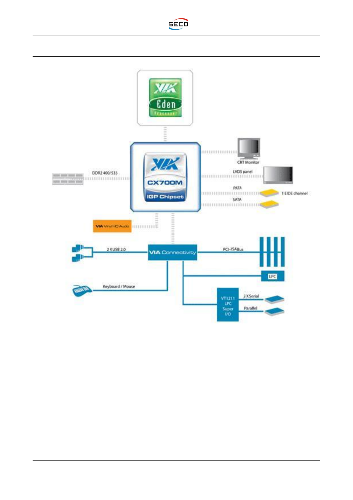
Supporting DDR2 533/400 memories, up to 1GB on one SODIMM socket, 1x Serial ATA and 1x
PATA devices, SECO104-CX700M board has the I/O connectors suitable for most of the
embedded systems: 2 serial ports, 1 parallel, 2 USB 2.0, 1 Ethernet port 10/100BaseT and the
PC/104-Plus format give the possibility for many additional features of the embedded system. All
this also is in fanless mode.
2.2 Technical Specifications
CPU :
-VIA EDEN®Ultra Low Voltage 500 MHz;
-VIA EDEN®Ultra Low Voltage 1 GHz.
DRAM: up to 1 GB DDR2 533/400 on SO-DIMM socket;
Chipset: VIA CX700MTM;
Graphic Controller: VIA UniChrome Pro II IGP with integrated MPEG-2, MPEG-4 and
WMV9 hardware decoder
CRT Resolutions: up to 2480x1536;
LCD Resolutions: up to 1600x1200 at 18 bit and 24 bit, single or dual channel.
Serial Ports: 1 x RS232 Full modem and 1 RS232FM/422/485 configurable;
USB: 2 x USB 2.0;
Parallel: SPP / EPP or ECP
Ethernet: 1 x Fast Ethernet 10/100baseT;
Serial ATA Interface
IDE interface: 1 x UltraDMA 100 mode on 44 pin conn;
Video: 1 x LVDS (18bit/24bit) and 1 x CRT outputs;
Audio: In/Out dual channel, 2.2W per channel;
PS/2 mouse and keyboard connectors
PC/104 Plus expansion
BIOS: advanced managing functions;
Battery-backed Real Time Clock
Watch Dog Timer
Power Supply Voltage: +5V ±5%
Operative systems:
Windows®XP®
Windows®XP Embedded®
Windows®CE®
Linux
StockCheck.com

SECO104-CX700M
User Manual - Rev. First Edition: 1.0 - Last Edition: 3.1 - Author: S.B. - Reviewed by G.M.
Copyright © 2011 SECO s.r.l.
SECO104-CX700M
pag. 11
2.3 Electrical specifications
2.3.1 Power Connector
SECO104-CX700M is powered through the dedicated connector CN15, which is a 5-pin 2.54mm
pitch male connector, type PHOENIX CONTACT MC0.5/5G-2.5. Refer to the following table for the
pin assignment.
CN15 –Power connector
PIN
SIGNAL
1
+5VDC
2
+5VDC / --12VDC (JP2 config.)
3
+12V
4
GND
5
GND
It’s strictly recommended, if external –12VDC is not needed, to use pin 2 for a second
connection to +5VDC power supply.
Furthermore, it’s better to use cables of minimal length (the minimum required for intended
applications, possibly not more than 20-25 cm), using separate wires for each GND and
+5VDC voltages.
It’s also recommended the use of wires with a cross section of 0.5mm2(AWG20, maximum
section allowed by the connector).
SECO104-CX700M requires only an external +5VDC and generates all the other voltages internally,
through a supply module mounted vertically on the two dedicated connectors.
+12VDC is internally used only to produce a switched supply voltage for inverter units for flat panels’
lamps; this is switched by a MOSFET driven by the graphic controller, allowing to turn on and off
the inverter unit.
If SECO104-CX700M board has to be used with PC/104+ expansion boards, is recommended
to power the board via PC/104+ pins, because these pins are capable of supplying greater
currents. Since using expansion boards increases sensibly power consumptions, this
solution has to be preferred, is possible.
2.3.2 RTC Battery
A 3.3V Rechargeable Lithium Battery supplies the Real Time Clock (RTC), which is built-in in the
VIA CX700MTM Chipset
The battery used is a Panasonic ML1220/F1A Battery, with a capacity of 17mAh. This battery can
grant the charge duration for a period of 2 months in total lack of power supply.
These new batteries are factory charged for first time during functional tests, and are sent to
customers already charged.
However, exactly like for all handheld devices provided with rechargeable batteries, we
recommend that all customers, during first installation of SECO104-CX700M boards, keep the
boards supplied for at least 12 hours, in order to restore battery’s optimal conditions”.
In case the internal battery is not working, or you think its characteristics are not suited for your
applications, you can use pin 1 of UTIL connector (CN9) to connect an external 3V backup battery.
Remember the board does not provide recharge circuitry for this external battery.
StockCheck.com
SECO104-CX700M
User Manual - Rev. First Edition: 1.0 - Last Edition: 3.1 - Author: S.B. - Reviewed by G.M.
Copyright © 2011 SECO s.r.l.
SECO104-CX700M
pag. 12
Batteries supplied with SECO104-CX700M board are compliant to requirements of European
Directive 2006/66/EC regarding batteries and accumulators. When putting out of order SECO104-
CX700M board, remove the batteries from the board in order to collect and dispose them
according to the requirement of the same European Directive above mentioned. Even when
replacing the batteries, the disposal has to be made according to these requirements.
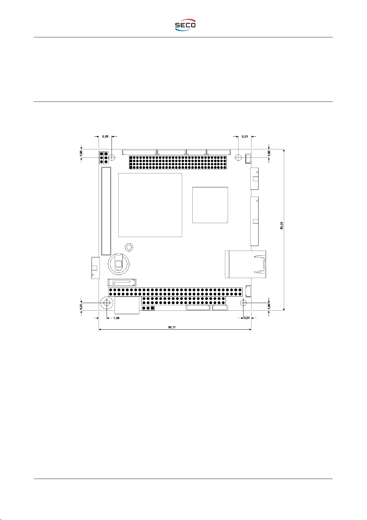
2.4 Mechanical specifications
According to PC/104-Plus Standard specifications, board dimensions are 90 x 96 mm (3.6” x 3.8”).
The printed circuit of the board is made of ten layers; some of them are ground planes, for
disturbance rejection.
StockCheck.com
SECO104-CX700M
User Manual - Rev. First Edition: 1.0 - Last Edition: 3.1 - Author: S.B. - Reviewed by G.M.
Copyright © 2011 SECO s.r.l.
SECO104-CX700M
pag. 13
2.5 Block Diagram
StockCheck.com

SECO104-CX700M
User Manual - Rev. First Edition: 1.0 - Last Edition: 3.1 - Author: S.B. - Reviewed by G.M.
Copyright © 2011 SECO s.r.l.
SECO104-CX700M
pag. 15
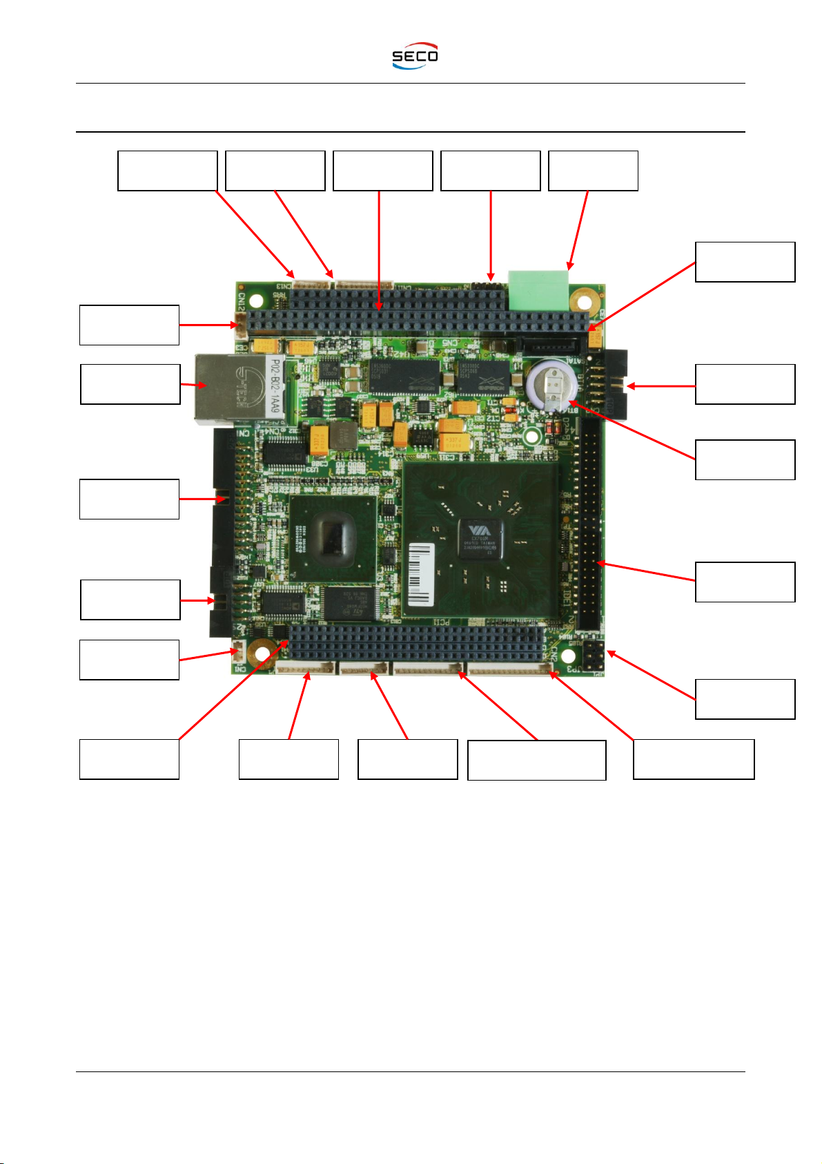
3.1 Connectors placement
CN15 Power
Connector
Jumper JP2
CN12 –Dual
Audio
CN10 –COM2
JP1 –JP4
Jumpers
CN11 –COM1
CN7 –
Parallel/Floppy
CN2 –LVDS
Primary Channel
PC/104+ Exp.
Bus PCI
FAN
CN13 - SPKR
L/R; MIC
P1 - CRT
CN4 -
Ethernet
CN8 –USB0-1
SATA
Connector
PC/104 Exp.
Bus ISA
IDE Connector
CN9 –Utility
Connector
Battery
CN3 –LVDS
Secondary Channel
StockCheck.com
SECO104-CX700M
User Manual - Rev. First Edition: 1.0 - Last Edition: 3.1 - Author: S.B. - Reviewed by G.M.
Copyright © 2011 SECO s.r.l.
SECO104-CX700M
pag. 16
3.2 Connectors overview
Name
Description
CN1
Fan connector
CN2
LVDS Primary Channel connector
CN3
LVDS Secondary Channel connector
P1
CRT Connector
CN4
Fast Ethernet 10/100baseT connector
CN5 –CN6
PC/104 ISA Bus expansion connectors
CN7
Parallel port connector
CN8
USB 0-1 Port connector
CN9
Utility connector
CN10
COM2 serial port connector
CN11
COM1 serial port connector
CN12
Dual Audio Amplified connector
CN13
Speaker L/R –MIC connector
CN15
Power connector
PCI1
PC/104+ PCI Bus expansion connector
SATA
Serial ATA connector
IDE1
Primary IDE HD Connector
DDR2
DDR2 SO-DIMM socket
JP1- JP2 –JP4
Configuration Jumpers
StockCheck.com

SECO104-CX700M
User Manual - Rev. First Edition: 1.0 - Last Edition: 3.1 - Author: S.B. - Reviewed by G.M.
Copyright © 2011 SECO s.r.l.
SECO104-CX700M
pag. 17
3.3 Connectors description
3.3.1 FAN connector
CN1 connector provides an auxiliary power connector to supply an eventual +5VDC fan to cool the
CPU. The connector is a single row, 3 pin, male, straight, P1.25 connector, type MOLEX 53047-
0310 or equivalent.
CN1 - FAN Connector
PIN
SIGNAL
1
GND
2
VCC
3
NC
3.3.2 LVDS Channels Connectors
CN2 and CN3 connectors report each four LVDS differential couples from the two internal
channels of the CX700MTM graphic interface. CN2 makes also available the supply voltage for the
LCD panel (VCCLCD) and for the backlight inverter module (VBACKLIGHT), driven both by the graphic
controller. First channel, available on CN2 connector, has to be used for connection of standard 18
or 24 bit TFT displays. VCCLCD voltage can be set at the value of +5VDC or +3.3VDC, using jumper
JP1 (see paragraph 3.3.17). VBACKLIGHT is fixed at +12VDC.
Second channel has to be used only for connection of 18 or 24 bit dual pixel/clock displays (in this
case it is necessary to use both connectors).
CN2 is a single row, 15 pin, male, straight, P1.25 connector, type MOLEX 53047-1510 or
equivalent.
CN3 is a single row, 12 pin, male, straight, P1.25 connector, type MOLEX 53047-0310 or
equivalent.
LVDS CHANNELS CONNECTORS
CN2 –Primary Channel
CN3 –Secondary Channel
PIN
SIGNAL
PIN
SIGNAL
1
TXOUT0-
1
TXOUT0+
2
TXOUT0+
2
TXOUT0-
3
TXOUT1-
3
TXOUT1+
4
TXOUT1+
4
TXOUT1-
5
TXOUT2-
5
TXOUT2+
6
TXOUT2+
6
TXOUT2-
7
GND
7
GND
8
TXCLK-
8
TXCLK+
9
TXCLK+
9
TXCLK-
10
GND
10
GND
11
VCCLCD
11
TXOUT3+
12
VCCLCD
12
TXOUT3-
13
VBACKLIGHT
14
TXOUT3+
15
TXOUT3-
StockCheck.com

SECO104-CX700M
User Manual - Rev. First Edition: 1.0 - Last Edition: 3.1 - Author: S.B. - Reviewed by G.M.
Copyright © 2011 SECO s.r.l.
SECO104-CX700M
pag. 18
3.3.3 CRT Connector
P1 connector provides signals to connect VGA CRT monitor.
It is a single row, 10 pin, male, straight, P1.25 connector, type MOLEX 53047-1010 or equivalent. It
is named also as CRT.
P1 CRT CONNECTOR
PIN
SIGNAL
1
RED
2
GND
3
GREEN
4
GND
5
BLUE
6
GND
7
HSYNC
8
GND
9
VSYNC
10
GND
3.3.4 Fast Ethernet connector
CN4 is a RJ45 type connector, type HALO HFJ11-2450E-S1RL or equivalent, with integrated
magnetics, that provides direct connection to a 10/100-BaseTx Ethernet.
CN4 - Fast ETHERNET CONNECTOR
PIN
SIGNAL
1
TX+
2
TX-
3
RX+
4
Termination to GND
5
Termination to GND
6
RX-
7
N.C.
8
GND
3.3.5 ISA PC/104 BUS Expansion connector
CN5 connector is a 64 pins double row female one (2 x 32 pin, pitch 2,54 mm) and carries out ISA
signals necessary for the use of 8 bit I/O boards. This solution allows to connect PC/104 boards to
SECO104-CX700M board, making it a flexible solution for different configurations.
Signals of CN5 expansion connector are shown in the table below:
StockCheck.com
SECO104-CX700M
User Manual - Rev. First Edition: 1.0 - Last Edition: 3.1 - Author: S.B. - Reviewed by G.M.
Copyright © 2011 SECO s.r.l.
SECO104-CX700M
pag. 19
CN5 - ISA PC/104 Bus Connector
Pin
Signal
Pin
Signal
A1
I/O CHCK#
B1
GROUND
A2
DATA BIT 7
B2
RESET
A3
DATA BIT 6
B3
+5VDC
A4
DATA BIT 5
B4
IRQ9
A5
DATA BIT 4
B5
N.C.
A6
DATA BIT 3
B6
DMA REQ. 2
A7
DATA BIT 2
B7
-12 VDC
A8
DATA BIT 1
B8
N/C
A9
DATA BIT 0
B9
+12 VDC
A10
I/O READY#
B10
GROUND
A11
ADDRESS ENABLE
B11
MEM WR#
A12
ADDRESS A19
B12
MEM RD#
A13
ADDRESS A18
B13
I/O WRITE#
A14
ADDRESS A17
B14
I/O READ#
A15
ADDRESS A16
B15
DMA ACK 3#
A16
ADDRESS A15
B16
DMA REQ 3
A17
ADDRESS A14
B17
DMA ACK 1#
A18
ADDRESS A13
B18
DMA REQ 1
A19
ADDRESS A12
B19
MEM REFRESH#
A20
ADDRESS A11
B20
ISA CLOCK (8 or 16 MHz)
A21
ADDRESS A10
B21
IRQ7
A22
ADDRESS A9
B22
IRQ6
A23
ADDRESS A8
B23
IRQ5
A24
ADDRESS A7
B24
IRQ4
A25
ADDRESS A6
B25
IRQ3
A26
ADDRESS A5
B26
DMA ACK 2#
A27
ADDRESS A4
B27
TERM COUNT
A28
ADDRESS A3
B28
ADDRESS LATCH ENABLE
A29
ADDRESS A2
B29
+ 5VDC
A30
ADDRESS A1
B30
14.3 MHz CLOCK
A31
ADDRESS A0
B31
GROUND
A32
GROUND
B32
GROUND
StockCheck.com

SECO104-CX700M
User Manual - Rev. First Edition: 1.0 - Last Edition: 3.1 - Author: S.B. - Reviewed by G.M.
Copyright © 2011 SECO s.r.l.
SECO104-CX700M
pag. 20
CN6 connector is a 40 pins double row female one (2 x 20 pin, pitch 2,54 mm) and carries the
signals necessary for using 16 bit I/O boards.
CN6 - EXPANSION CONNECTOR
PIN
SIGNAL
PIN
SIGNAL
C1
GROUND
D1
GROUND
C2
SBHE#
D2
16BIT MEMORY ACCESS #
C3
ADDRESS A23
D3
16 BIT I/O ACCESS#
C4
ADDRESS A22
D4
IRQ10
C5
ADDRESS A21
D5
IRQ11
C6
ADDRESS A20
D6
N.C.
C7
ADDRESS A19
ID7
IRQ15
C8
ADDRESS A18
D8
IRQ14
C9
ADDRESS A17
D9
DMA ACK 0#
C10
MEMORY READ#
D10
DMA REQ 0
C11
MEMORY WRITE#
D11
DMA ACK 5#
C12
DATA 8
D12
DMA REQ 5
C13
DATA 9
D13
DMA ACK 6#
C14
DATA 10
D14
DMA REQ 6
C15
DATA 11
D15
DMA ACK 7#
C16
DATA 12
D16
DMA REQ 7
C17
DATA 13
D17
+5 VDC
C18
DATA 14
D18
N.C.
C19
DATA 15
D19
GROUND
C20
KEY LOCATION
D20
GROUND
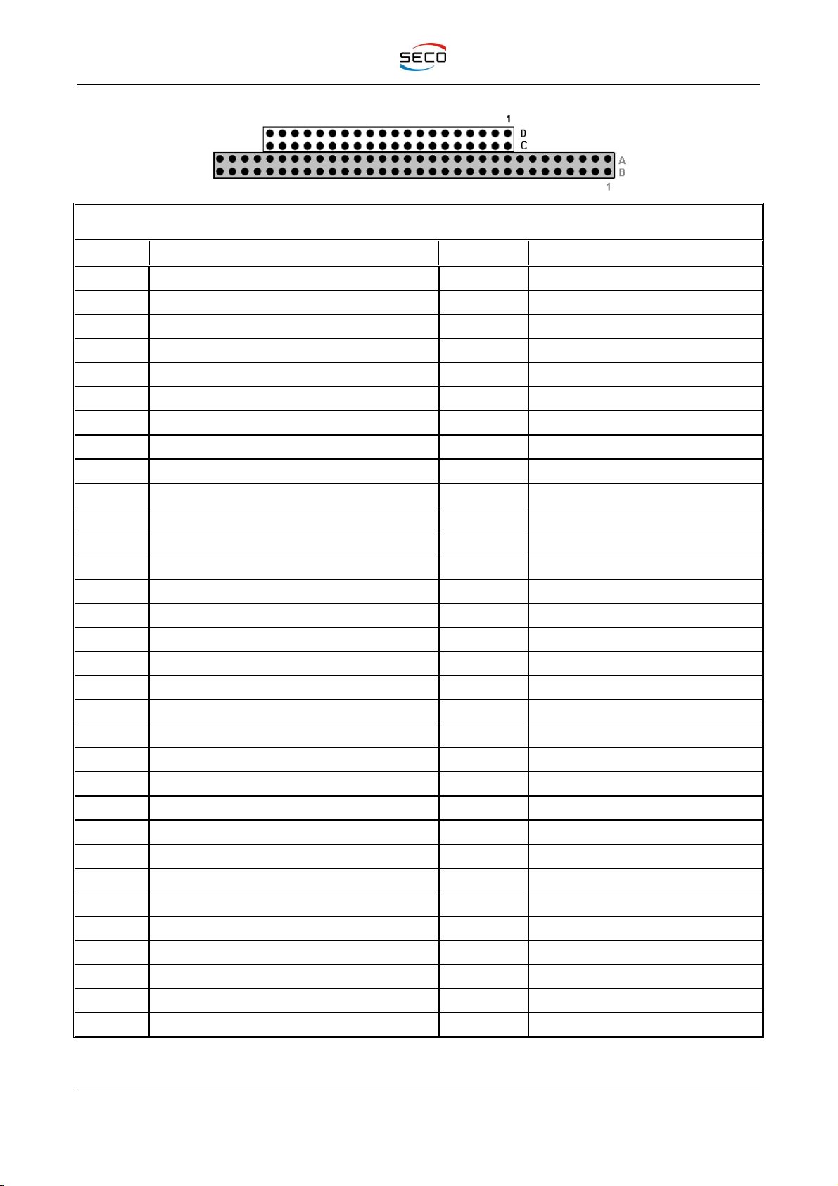
3.3.6 PC104+ PCI BUS Expansion connector
PCI1 connector is a 120 pins 4 rows female connector, and carries out PCI signals, as defined in
PC/104+ standard specifications. This solution allows connecting compatible PC/104+ boards with
the CPU module.
Signals of PCI1 expansion connector are shown in the following table:
Connector: SAMTEC ESQT-130-03-L-Q-368 type or equivalent (Female, 4 x 30 pin, pitch 2 mm)
StockCheck.com
Table of contents
Other Seco Control Unit manuals

Seco
Seco Qseven Q7-B03 User manual

Seco
Seco Smarc SM-B69 User manual

Seco
Seco SM-C12 User manual

Seco
Seco Smarc SM-C93 User manual

Seco
Seco Q7-A29 User manual

Seco
Seco Smarc SM-B71 User manual

Seco
Seco Qseven mQ7-C72 User manual

Seco
Seco Qseven Q7-C26 User manual

Seco
Seco Q7-928 User manual

Seco
Seco Qseven Q7-974 User manual


