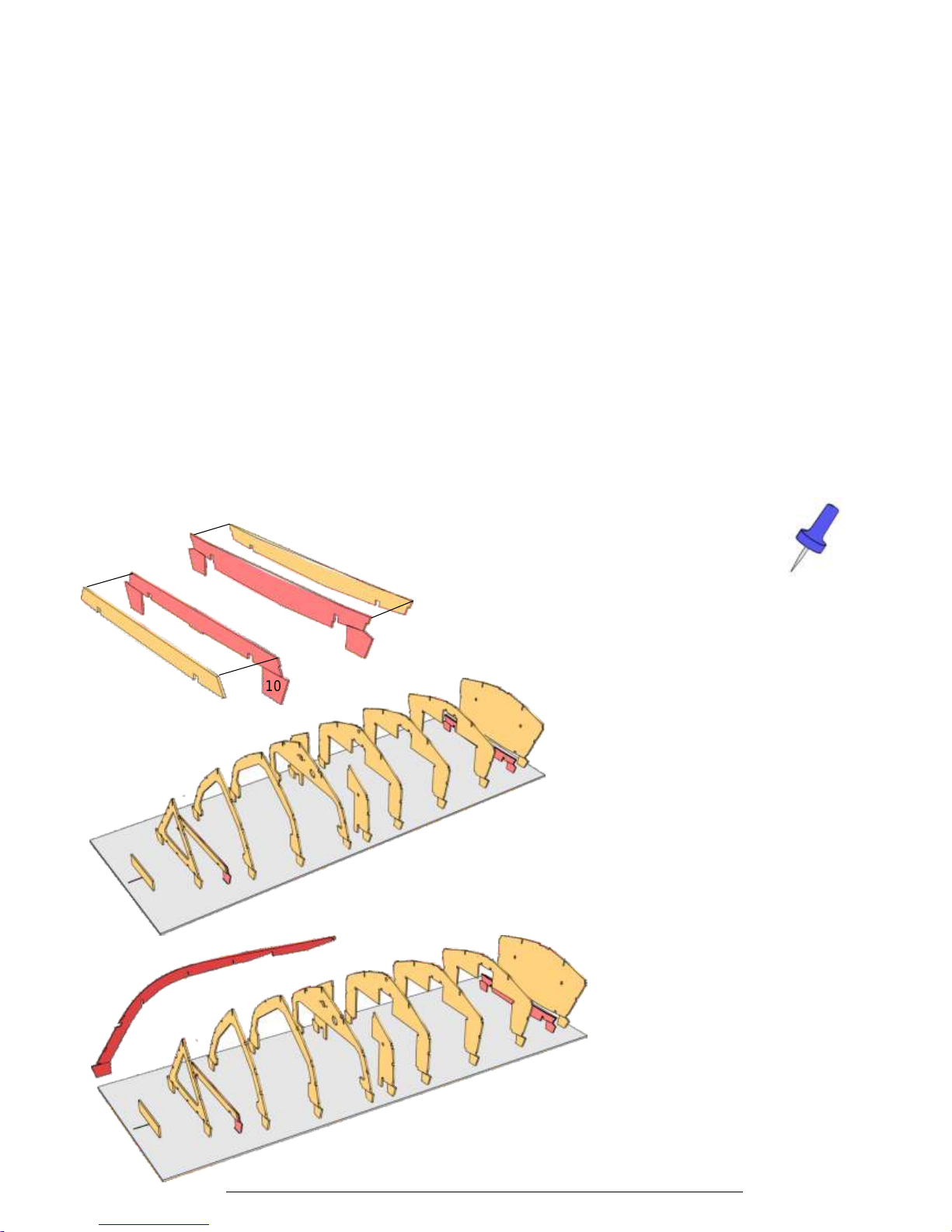
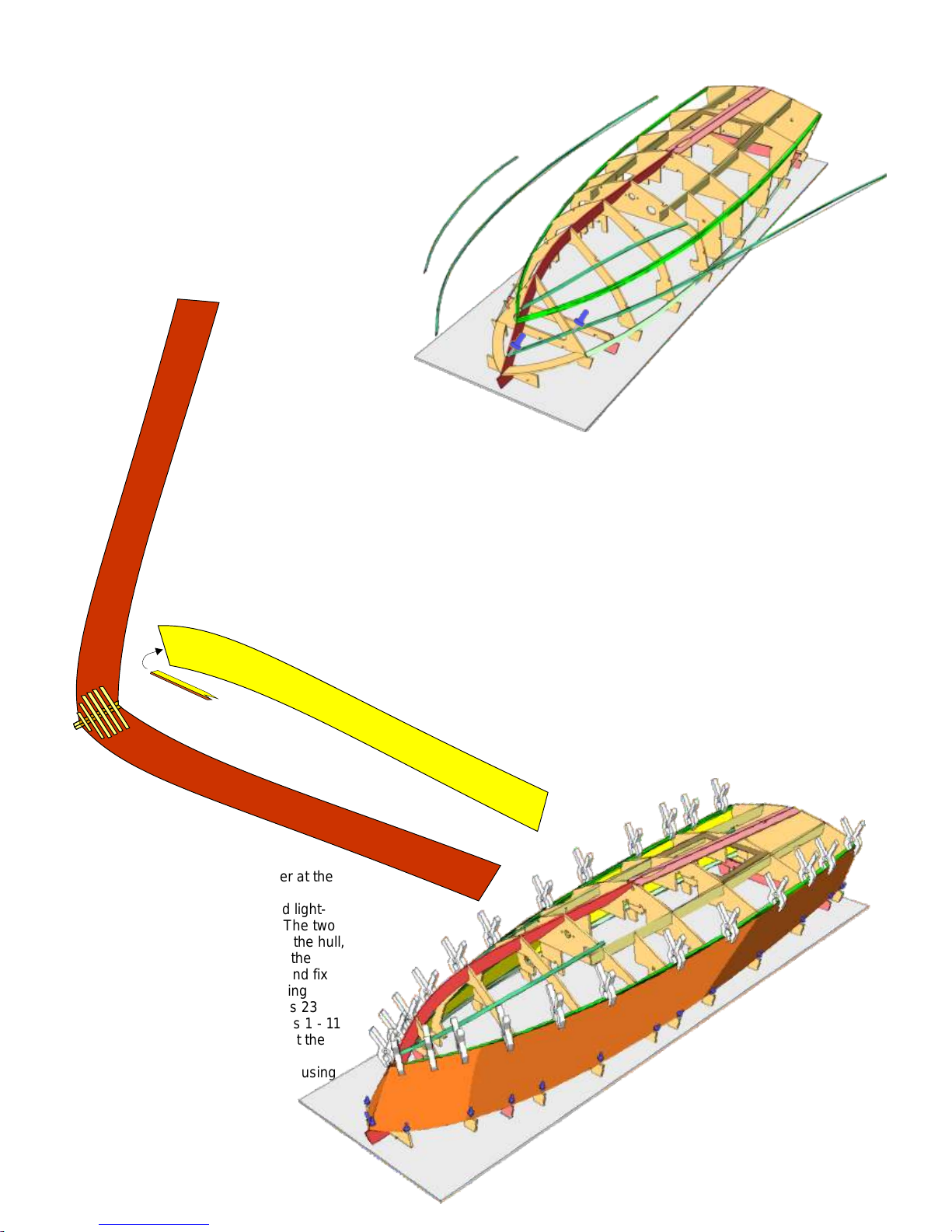
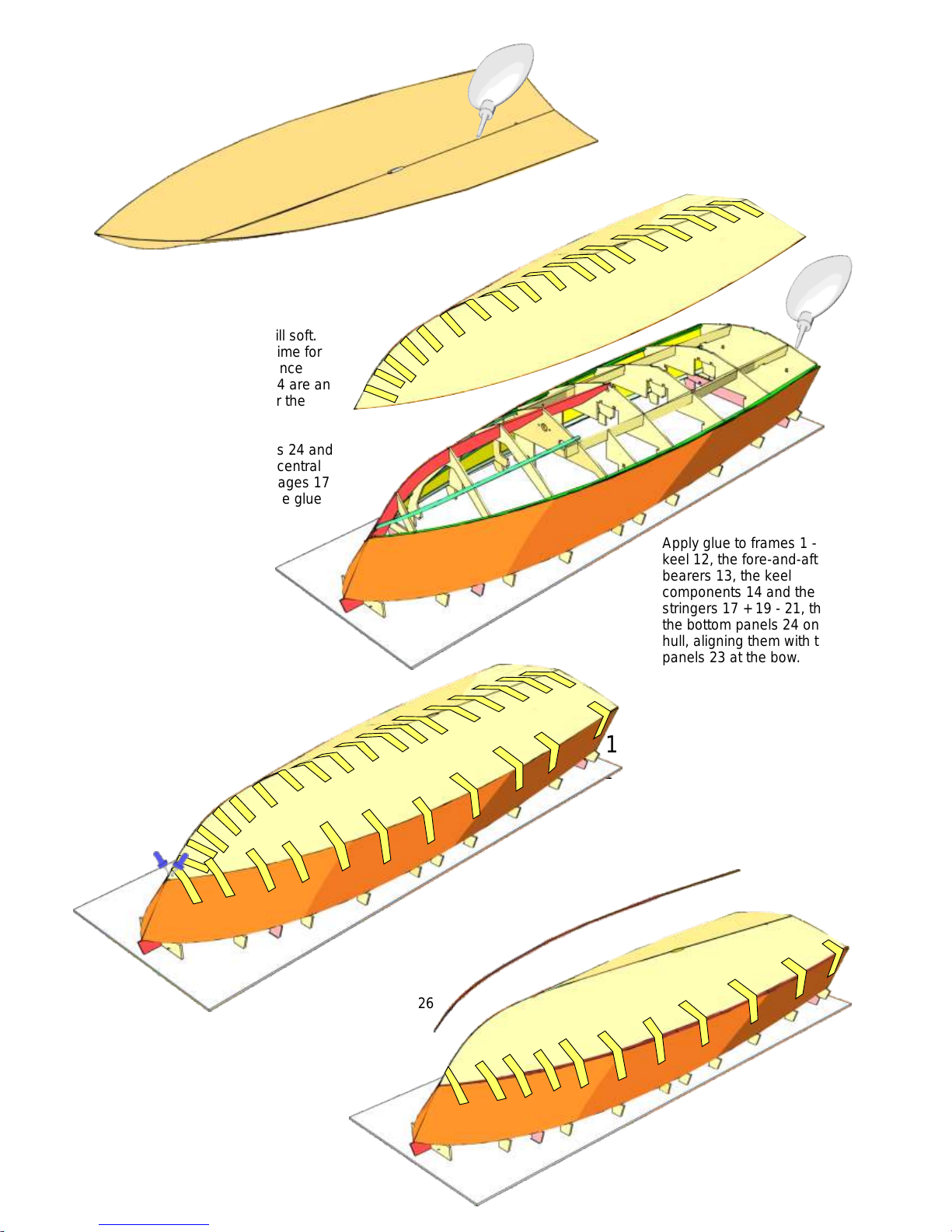
Aeronaut Queen Instruction Manual


Other Aeronaut Toy manuals

Aeronaut
Aeronaut Aero-Maxx Instruction Manual

Aeronaut
Aeronaut Jonny User manual

Aeronaut
Aeronaut Galaxy Instruction Manual

Aeronaut
Aeronaut Rambotator User manual

Aeronaut
Aeronaut LT 200 Flex User manual

Aeronaut
Aeronaut 3033/00 User manual

Aeronaut
Aeronaut Quido User manual

Aeronaut
Aeronaut Mowe 2 User manual

Aeronaut
Aeronaut Manta A 02 User manual

Aeronaut
Aeronaut RX-3 User manual

Aeronaut
Aeronaut Twinspeedy User manual

Aeronaut
Aeronaut Scarlet Instruction Manual

Aeronaut
Aeronaut BLADE 2 Instruction Manual

Aeronaut
Aeronaut The Hansa-Jolle Instruction Manual

Aeronaut
Aeronaut SkyMAXX User manual

Aeronaut
Aeronaut Pilot User manual

Aeronaut
Aeronaut LUXX Instruction Manual

Aeronaut
Aeronaut Lilienthal 40 RC User manual

Aeronaut
Aeronaut Princess User manual

Aeronaut
Aeronaut Sukhoi SU 31M Instruction Manual


Popular Toy manuals by other brands


TINY LAND
TINY LAND Wooden Train Set-74 Pcs Assembly instructions

PlayMonster
PlayMonster Roominate Cozy Corner Cafe instructions

yourDroid
yourDroid D2-6 instructions

Lionel
Lionel 2-8-4 Berkshire Locomotive and Tender owner's manual

Lionel
Lionel 2-8-4 Berkshire Locomotive and Tender owner's manual

RCRCM
RCRCM Hornet Motor Glider Build manual

Agora Models
Agora Models Bismarck 08 Build instructions

Black Horse Model
Black Horse Model Sputnik Instruction manual book

Rollplay
Rollplay W461-G Owner's manual and assembly instructions

Mega Construx
Mega Construx CALL OF DUTY BLACK FRANK WOODS GNV44 manual

Value Hobby
Value Hobby Piper J3 Cub 40 instruction manual

THE WORLD MODELS
THE WORLD MODELS Extra 300 EP instruction manual