manuals.online logo
Brands
  1. Home
  2. •
  3. Brands
  4. •
  5. Aeronaut
  6. •
  7. Toy
  8. •
  9. Aeronaut The Hansa-Jolle Instruction Manual

Aeronaut The Hansa-Jolle Instruction Manual

Order No. 3011/00
Building instructions in English
can be downloaded from our website:
www.aero-naut.com
Vous pouvez télécharger la notice de
construction à parti de notre site web:
www.aero-naut.fr
English version
Many thanks for placing your faith in us by purchasing this model kit. We hope and trust that you will have many hours of pleasure
building and sailing the model.
The Hansa-Jolle
Full-size vessel
The Hansa-Jolle was first introduced in 1947 by Henry Rasmussen, the founder of the renowned Abeking & Rasmussen (A&R) boat and
yacht yard based at Lemwerder, near Bremen. It was based on a design dating from the year 1920. At that time Henry Rasmussen was
building a small yawl named VISKA for two friends in Copenhagen, and these boats were used for quite extended single-handed voyages
in the Scandinavian Baltic region. The vessel turned out to be a particularly good performer, and after the war this encouraged the
dockyard to make a new start in boat-building, since crew regulations prohibited the construction of larger boats. The freeboard and
draught of the VISKA design were increased, and - most importantly - a permanent, enclosed cabin superstructure was added.
For a period of about twenty years Abeking & Rasmussen built quite large numbers of the boat under the “Hansa-Jolle” name, and the
type's excellent handling soon found it a home in many sailing regions. In 1960 the vessel was finally recognised as a national class by the
DSV (German Sailing Association). The A&R dockyard had maintained a monopoly for the construction of the Hansa-Jolle until this time,
but now made the plans freely available for other boat yards to build the craft.
Actually the term Jolle (yawl) is not correct, as the Hansa-Jolle's integral ballast keel, fixed fin and draught of 50 cm ranks it as a
centreboard boat. The keel ballast of 150 kg and the beam of 1.65 metres endow the sailing boat with good stability. Although the
Hansa-Jolle is unsinkable due to its sealed foam-filled buoyancy tanks, it is not proof against capsizing.
Specification:
Overall length: 5.85 m Effective sail area: 14.00 m²
Waterline length:4.85 m Mainsail: 10.50 m²
Overall beam: 1.65 m Jib: 4.05 m²
Freeboard: 0.68 m
Draught: 0.50 / 1.00 m Rig: Sloop
Weight: 510 kg Class: National standard class
Ballast: 160 kg
Model
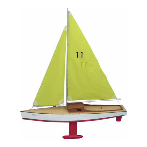
The model is based loosely on the full-size Hansa-Jolle, and is intended as a sailing boat for light-wind conditions. It features a high-
quality plastic hull shell, but in every other respect is of traditional all-wood construction. This combination makes it easy for the
modeller to produce a boat which is by its nature watertight. If you wish to be able to sail the model in stronger winds, you will need to
fit a removable supplementary ballast weight to the centreboard.
Specification:
Scale: 1 : 6.5 Effective sail area: 32 dm²
Overall length: 900 (with rudder 940 mm) Mainsail: 23 dm²
Waterline length:750 mm Jib: 9 dm²
Overall beam: 260 mm
Freeboard: 63 mm Rig: Sloop (jib)
Draught: 84 / 38 mm
Weight: 1.40 kg
Ballast: 1.50 kg
The RC equipment and accessories required to control the model are not included in this kit. Please ask your model shop for advice on
appropriate equipment. Relatively high-power servos are required for this model.
aero-naut Modellbau GmbH & Co. KG
Stuttgarter Strasse 18-22
D-72766 Reutlingen
www.aero-naut.com
Please read right through these instructions before starting construction, so that you always have a clear idea of the next stage.
These instructions assume that you are familiar with the proper use of modelling tools, materials and adhesives. If this is not so, please
ask an experienced modeller for guidance. This kit is not suitable for young persons under fifteen years of age. In these instructions the
stages of construction are numbered sequentially, and each step is complemented by a suitable illustration. We recommend that you
keep to the order of work as described.
The kit contains the following groups of components and items:
- Model stand
- Hull shell
- Hull framework
- Deck planking
- Hull fittings set, cockpit
- Hull fittings set, cabin
- Rudder and linkage
- Mast and mast heel, boom, cords and fittings
- Sail suit with cords and fittings
- Additional parts (optional ballast)
We strongly recommend that you apply a waterproof lacquer to all the wooden parts to seal them before they are permanently glued
to the model. The basic procedure is to assemble the parts of the sub-assembly, glue the joints, and then seal the surfaces. The treated
surfaces should then be rubbed down using fine abrasive paper (240-grit). Areas of the sub-assembly which are to be joined to other
parts must be sanded back to bare wood before glue is applied.
It is best to seal the mahogany components with sanding sealer before they are removed from the sheet, taking care to avoid the sealer
running onto the other side through the cut lines and openings. The edges and surfaces of all parts must be cleaned up (sanded) before
fitting. The laser-cut parts in particular feature burned edges, and the blackened surfaces should also be sanded carefully to remove the
discoloration. Numbers are printed on all the components, reflecting the sequence of their assembly. We recommend that you
constantly refer to the Parts List, which includes all the kit components.
We recommend the following adhesives for use when building this model:
Wood - wood: white glue, e.g. UHU COLL EXPRESS, Order No. 7634/11 or PONAL EXPRESS, Order No. 7638/09, Beli-Zell, Order No.
7646/46
Wood - plastic: UHU PLUS ACRYLIT, Order No. 7633/09
or PATTEX STABILIT, Order No. 7646/02, Beli-Zell, Order
No. 7646/46.
Before starting construction please check against the
Parts List that all the kit components are present.
1
We will start by assembling the boatstand.
The stand is built as shown in the drawing, and ensures
that the model can be supported securely during
construction, and can subsequently be stored and
transported safely.
Push the horizontal aluminium tubes (3) through the
two stand end-plates (1) and (2), allowing them to
project by 3 mm. Use a centre-punch to splay the ends
of the aluminium tubes, then push the end-plates
outwards until they are a tight fit.
Stick the felt strips (4) to the upper aluminium tubes
using double-sided adhesive tape. Rotate the
aluminium tubes inwards by a quarter-turn, so that the
metal does not contact the keel.
1
2
3
44
4
10
6
2
Construction of the model itself starts with the assembly
of the internal hull framework, which consists of three
sections:
- the bow section with a central keel extending as far as
the cabin,
3
- the midship section including the cabin and the cockpit,
with two keels,
4
- and the stern section with a single keel and a deck
beam running from the cockpit to the stern. The stern
section is the last part to be made, and is assembled
inside the hull itself. The two first sub-assemblies can be
assembled outside the hull shell, which makes it easy to
keep them straight and true, and also makes it possible
to seal the parts thoroughly before they are installed.
5
Caution: many components in this kit have to be
'doubled', i.e. two identical parts are stuck together
using white glue before they are lacquered. The glued
joints must be secured with screw-clamps or spring-clips
until the glue has set hard (see the processing
information supplied by the glue manufacturer).
There is a danger that the joined parts will deform due to
the moisture in the glue: use clamps to prevent this.
The first step is to glue together the components of the
central bow section plates.
These parts are:
- the keel and stem which form the bow (6)
- the forward deck bearer (10).
6
The first step is to glue the parts together in pairs to form
4 mm thick plates. Keep all the edges exactly flush, and
please take care to keep these parts straight while the
glue is drying. This is best accomplished by clamping or
weighting them down on a perfectly flat surface while
the glue sets.
Clamp the parts together for the period recommended
by the glue manufacturer.
7
Some frames have to be fitted with 4 x 4 mm
reinforcing rails at specific locations: these parts are cut
from the 1000 mm long spruce strips in the kit; the
instructions state the actual length and position of each
one.
Please take care not to mix up the front and rear (bow /
stern side) of the frames. All the frames are numbered,
and the printing is on the bow face. These parts are not
symmetrical, and are therefore not interchangeable.
The solid lines represent the reinforcements on the
bow face, the dotted lines those on the stern face.
The drawing alongside shows where the bow-side
reinforcement (31) has to be fitted to frame 3, part
(30). The rail is 150 mm long and - like all the rails - is
positioned centrally on the frame, in this case
immediately below the openings.
8
This illustration shows where the stern-side
reinforcements (32) have to be fitted to the same
component (30).
The vertical strips are 75 mm long.
Please take care to position these rails accurately: they
should not be fitted flush with the slots, but spaced
slightly away from them (~0.5 mm). This allows for minor
widening of the slots (by sanding) when the bench-seat
is installed later.
9
This drawing shows where the bow-side reinforcement
(22) is to be fitted to frame 4, part (21).
This reinforcing rail (22) is 153 mm long. Fit this rail, and
the rail on the opposite face, flush with the top edge of
the frame.
10
This drawing shows the position of the stern-side
reinforcement (23) on part (21).
The rail (23) is 194 mm long.
30
31
30
32
21
22
21
23
36
33
37
34
35
1,5 mm
6mm
6mm
60mm
17mm
11
The next step is to glue the pairs of parts together to
form the stern deck bearer (36) and the stern keel (33).
The parts are as follows:
- the keel plate (33)
- the stern deck bearer plate (36)
Glue these parts together using the procedure outlined
above.
12
This drawing shows how the parts are clamped together
while the glue is drying.
The same general procedure should be adopted
wherever white glue is used to join, or 'double' parts.
The result is strong, permanent joints and rigid
components.
If the parts are simply placed together and left to dry -
without clamping - the joints may fail again later.
13
In this drawing you can see where the 8 x 8 mm spruce
reinforcing rail (35) has to be glued to frame 1, part
(34).
The rail (35) is 60 mm long, and is glued to the frame at
a point 17 mm from its bottom edge.
Drill a central 1.5 mm Ø hole in each end of the rail, at a
point 6 mm from either end.
14
Glue parts (37) together in pairs to form the 4 mm thick
frames 2, as described earlier for the keel components.
Keep the edges flush all round.
15
Attach the bow-side reinforcing rail (19) to frame 5,
part (18).
This rail (19) is 165 mm long and is fitted flush with the
top edge, as is the reinforcement on the other side.
16
Now yet the stern-face reinforcement (20) to part (18).
The reinforcing rail (20) is 206 mm long.
17
Here we see the location of the bow-side reinforcement
(16) on frame 6 (part 15).
The reinforcing rail (16) is 100 mm long, and runs parallel
to the bottom edge of the opening at a point 13 mm
below it, as shown in the drawing.
18
This drawing shows where the stern-side reinforcement
(17) is fitted to part (15).
The reinforcing rail (17) is 210 mm long. This rail should
also be positioned 13 mm from the bottom of the
opening.
18
19
18
20
15
16
13mm
13mm
15
17
12
13
14
19
The illustration alongside shows the position of the
bow-side reinforcing rails (13) and (14) on frame 7, part
(12).
Rails are only fitted to one face of this frame.
Note that the upper rail is not fitted until the side
panels have been fitted.
The upper rail (13) is 204 mm long,
the lower rail (14) is 190 mm long.
Both these reinforcements are attached to the bow face
only, so that the plate remains flexible, and can be bent
backwards later!
26
27
28
26
29
20Here you can see where the bow-side
reinforcements (27) and (28) are glued to frame 8, part
(26). The upper rail (27) is positioned flush with the top
of the openings, the rail (28) flush with the bottom of
the openings.
The upper rail (27) is 214 mm long,
the lower rail (28) is 130 mm long.
21
The vertical reinforcing rails (29) fitted to the stern-side
of frame 8 are 109 mm long, and are located flush with
the outside edge of the two keel slots at the bottom of
the frame.
22
This picture shows the method of clamping the
reinforcing rails when gluing them to the frame.
23
The next step is to assemble the removable door. The
parts are all flush on the rear surface. The in-fill panels
(53 and 55) can be sanded slightly thinner on the back
surface, so that they are recessed relative to the door
frame components.
This drawing shows the principle of construction:
The door is fitted by engaging the lugs in the openings
in frame 6, part (15).
In the interests of clarity the drawing shows the door
components from both sides.
24
The lugs are attached to the door as shown here.
The finished door is fitted to the front of frame 6, part
(15), while it is still loose: the lug components should be
glued to the door in such a way that they rest against
the bottom edge of the openings.
Ensure that the lugs are glued to the door only - not to
the frame.
25
This cut-away view shows the position of the retaining
lugs when the door is in place.
26
Once these parts have all been prepared as described,
they can be assembled to form the main internal sub-
assemblies.
Glue frame 11, part (7), frame 10 (part (8) and frame 9,
part (9) in the slots in the prepared stem keel 6.
Ensure that the frames do not project beyond the
underside of the keel.
52 50 60 59 52
56
55
58
54
53
51
15
58 57
50-56
59
60
98
7
6
56
55
58
54
53
51
57
10
mm
27
Insert the deck bearer (10) in the slots in the frames,
parts (7), (8) and (9), and glue the parts together.
28
The deck bearer (10) is also glued to the stem (6) at the
front. Check that all these parts finish flush with each
other.
This drawing also shows where the sub-assembly is
joined to the centre section by means of frame 8, part
(26); do not fit this part yet.
The sub-assemblies are not glued together until all of
them are completed to the appropriate point.
29
Now we move on to the centre section, where the two
keel components (11) are glued to the associated
frames, parts (12), (15), (18) and (21).
When fitting these frames please ensure that they are
fitted the right way round: all the markings on the
frames should face the bow.
On the port side (left, as seen from the stern) you will
find a series of small slots through which the snake for
the rudder linkage will be deployed later.
30
Once the frames are fitted to the keels, the
superstructure side panels can be fitted in turn.
Start with the port (left-hand) side panel, part (24).
Don't mix up the side panels, otherwise it will be
impossible to install the rudder linkage subsequently.
Note that there is a slot in the port side panel through
which the snake runs to the rudder servo.
10
98
76
10
6
21 18 15 12
11
24
26
31
Now fit the second side panel, part (25), on the
starboard (right-hand) side, and glue all the joints.
32
Once the side panels (24 and 25) are in place, the final
reinforcing rail (13) (length 204 mm) can be fitted
through the square holes and glued to part (12). The rail
should only be glued to part (12) outside the cabin side
panels.
33
Please be sure only to glue the reinforcing rail (13) to
the frame outside the cabin area. If you neglect this, it
will not be possible to 'spring' the frame back; this is
necessary in order to secure the mounting plates for
the radio control equipment.
34
This drawing shows the underside of the centre section
from an angle, showing the current stage of
construction.
25
13 12
12
13
35
The front cabin panel (38) can now be inserted between
the cabin sides (24 and 25) at the front, but do not glue
it at this stage. The front panel should not be glued in
place until frame 8, part (26), is fitted and glued in
place.
It is a good idea to wrap a rubber bound round the
structure as shown, so that the ends of the side panel
curve inward slightly, preventing the front panel from
falling out. When the front and rear frames have been
attached to this section, the rubber band should be cut
through to avoid damaging the components.
36
At this stage the front and rear frames, parts (26) and
(30), can be fitted to the structure and glued in place:
Frame 8, part (26), at the bow end,
Frame 3, part (30), at the stern end.
This is accomplished by carefully curving the side panels
inward until the tabs at the end engage in the slots in the
frames. Ensure that both frames make good contact with
the side panels.
37
This drawing shows a view of the structure at this stage,
with frame 8, part (26), in place.
38
Here we see the stern end of the structure with frame 3,
part (30), in place.
This sub-assembly is now complete; leave the glued
joints to harden thoroughly.
38
26
30
26
30
39
The next step is to fit the prepared sub-assemblies in
the hull, but first the exact position of frame 1, part
(34), has to be determined: position the frame in the
stern with its bottom edge resting in the bottom
corner of the hull shell. Detail drawing A shows the
exact position.
Use screw-clamps to fix the frame in place temporarily
to prevent it slipping, then use a 1.5 mm Ø bit to
continue the two holes right through the hull shell;
later these holes are used for the rudder pivot fittings.
The frame itself is not fitted until a later stage.
34
40
The sub-assemblies are installed in the hull starting at
the bow.
This drawing shows how the bow section is fitted in the
hull (5) and glued in place. Note that the keel (6) should
only be glued to the hull as far as frame 9, part (9).
Before reaching for the glue, check that all the frames
end flush with the top edge of the hull (deck position) on
both sides. If not, carry out any trimming now, otherwise
the deck will not fit properly.
41
With the bow section in place, the centre section can
be installed:
First insert the tabs at the end of the keel plate (6), and
the deck bearer (10) in the slots in frame 8, part (26).
When you are satisfied, glue these joints and the two
keels to the hull shell. The frames can now be glued to
the hull, working from the front end towards the stern.
As mentioned previously, it is essential that all the
frames end flush with the top edge of the hull on both
sides; don't glue them in place until this is so.
Check that the two pointed areas at the front of the
side panels (24) and (25) are equi-distant from the bow
(front point of the hull).
42
This drawing shows a detail of the assembled sections at
frame 8, part (26).
26
26 10
6
9
5
A
6
43
Detail view of the area between the bow and centre
section sub-assemblies at part (26), looking towards the
stern.
44
The keel component (33), which has already been
'doubled', can now be trimmed to fit in the stern: it
must fit flush at the front in the slot of frame 3, part
(30), and rest against the angled face of the inside of
the transom at the stern.
Carry out any minor trimming required.
When you are confident that everything fits, glue part
(33) to the slot in frame 3, (part 30) only.
45
Fit part (34) - the final frame - onto the keel component
(33) and check its position: the holes previously drilled
in the hull should line up with those in the frame; insert
short pieces of dowel or rod to check this. When you
are satisfied, glue the frame and the keel to the hull
using the appropriate adhesive.
46
Now glue part (36) - the rear deck bearer - to part (30)
and part (34).
Glue the deck frame 2, part (37), to the deck bearer
(36) only; this part is not fixed to the hull sides until
later, when the stringers are installed.
26
33
33
30
35
34
37
36
34
30
47
The next step is to assemble the cockpit bench-seat. The
seat / backrest unit is removable, providing access to the
interior of the hull behind it.
Once again parts have to be 'doubled' - glued together in
pairs - in order to produce the thickness required. As
mentioned earlier, it is essential that these parts are
clamped together and kept perfectly straight while the
glue is hardening.
Glue together the pairs of parts to form the bench-seat
backrest (43), the supports (44) and the seat squab (45).
48
Insert the seat supports (44) in the slots in the backrest
(43), and position them as shown in the drawing. The
tabs of the supports (44) can then be pushed right down
as far as they will go. Glue the parts in place. Caution:
wipe off any excess glue from the rear of the backrest,
otherwise parts (44) will not fit correctly through the hull
frame.
If the tabs are slightly too tight a fit, ease them slightly
using a file.
49
Trial-fit the bench-seat squab (45): it should end flush
with the backrest (43) on both sides. Glue the seat squab
to the backrest and both supports.
50
This is how the completed bench-seat should look when
installed in the model. The cut-away view shows how the
projecting tabs engage in the slots.
The slots in the frame enable the bench-seat to be fitted
and removed easily, while the openings in the frame give
access to the area of the hull behind it.
43
45
43
44 44
43
43
44
45
43
44
44
46
47
51
The next step is to install the bearers for the deck-
fittings for the stays and shrouds; these parts are cut
from 8 x 8 mm spruce strip.
The bearer (46) at the bow is 40 mm long, and should
be glued in place in the position shown in the drawing.
At a later stage the hole for the fitting itself is drilled
from above through the marked point on the deck.
52
The lateral bearers (47) for the shroud fittings are 95
mm long, and must be glued in place as shown in the
drawing alongside. They should project beyond the
frames by the same amount front and rear.
Once again, the mounting points for the fittings are
determined by the markings on the deck.
53
The two bearers (48) for the centreboard are located
in the bottom of the hull between the two centre
section keels (11). Cut a 3 x 3 mm slot in the front
bearer for the centreboard, then glue it to frame 7,
part (12), under the lower reinforcing rail; the slot is
indicated in this drawing.
Cut a 3 x 3 mm slot in the rear bearer, then fit it
centrally between frame 5, part (18), and frame 6, part
(15), at a point 4 mm below the top edge of parts (11).
18 15
48 48
12
48
11
11
49
21
54
The final bearer (49) is intended to support a ring-
screw which redirects a boom control cord; it is located
just forward of frame 4, part (21), facing the bow. Its
exact position is determined by the machined notches
in the two keels (11). The hole in this bearer is drilled
later; its position is determined by a hole in the cockpit
floor.
This drawing also shows the rear centreboard bearer
(48) from above.
47.1
47
11
55
The stringers are fitted next; they are cut from the 4 x
4 mm spruce strip material supplied.
The first step is to install the two outer stringers (39)
along the edge of the deck: start by fitting the
stringers 'dry' (without glue) at the bow, and work
steadily towards the stern. Clamp the stringers to the
edge of the hull shell as you progress, as this prevents
them bending between the frames; this can alter the
length of the stringer considerably. Cut the stringers to
the same length. When you are confident that the
strips are an accurate fit, glue them permanently to
the frames and the hull shell. Note that the stringers
must not project above the edge of the hull; if they do,
enlarge the notches in the frames slightly.
56
This is how the stringers fit at the bow and the frames.
You will need to trim the stay fitting bearer (46) slightly
at the ends to accommodate the stringers (39).
57
This picture of a typical area of the hull shows how the
stringers (39) are clamped to the hull side, allowing
them to be trimmed to length and glued in place
accurately.
Frame 2, part (37), can now be glued to the stringers.
58
With the outer stringers glued in place, the bow
stringers can be installed.
The foredeck stringers (40) extend from frame 8, part
(26), to frame 10, part (8); they should project slightly
at both ends. Check that they fit neatly, then clamp
them in place and glue the joints.
39
39
46
39
39
39
37
26
40 8
34
41
30
24
42
25
42
42
The stringers (41) are fitted to the stern next. These
parts extend from frame 1, i.e. part (34) as far as frame
3, part (30). At both ends they should be trimmed
carefully to fit flush; check that they butt up against the
seat backrest. The stringers (41) must not be too tight a
fit, i.e. they should not be overlength. When you are
satisfied, clamp them in place and apply glue to all the
contact points.
59
60
61
62
The final stringers to be fitted are parts (42), which run
along the sides of the cabin and cockpit.
Glue these stringers to the side panels (24) and (25) and
the associated frames.
These stringers (42) should also project slightly
beyond the final frames: both at the rear,
and at the front, i.e. past the frames on which they
rest.
61
64
63
62
65
65
18 mm
63
64
65
66
The next step is to install the centreboard (61).
Fit the centreboard through the machined slot in the
keel and into the case (slot) formed by the frames: push
it in as far as it will go; check that it engages in the slots
previously cut in the hardwood bearers.
When you are confident that the centreboard is
properly positioned, it can be glued permanently to the
hull. Make sure that all the joints are fully watertight.
Apply glue to all points inside the hull where the
centreboard makes contact with the wooden internal
parts.
The mounting plates for the RC system components are
installed next.
These plates also have to be 'doubled' in the familiar
way. Once again, keep the edges flush, and take care to
keep the components perfectly flat.
This drawing shows the battery plate (62), and the RC
installation plates 1 (63) and 2 (64); the former
supports the rudder servo and the mainsail setting
servo, while the latter supports the sail servo for the
jib.
While the joined RC support plates are drying out, you
can glue the spruce braces (65) and (66) inside the
cabin. These strips also support the frame of the
detachable roof, holding it at the correct height.
The braces are simply cut from the 4 x 4 mm spruce
strip supplied:
The two strips (65) are 83 mm long, and end flush with
the bottom edge of the side panels.
The distance between the top inside corner of the side
panel and the strip should be 18 mm.
Glue the braces to the inside corners of the cabin as
shown in the drawing alongside.
18 mm
18 mm 18 mm
46 mm
66
66
67
67
15
12 63 26
62
67
68
69
70
The braces at the bow end of the cabin should be 80
mm long, and also end flush with the bottom edge of
the side panels. The strips should be glued under the
top corners of the front cabin panel, as shown in the
drawing; the roof frame rests on these strips later. The
distance between the top inside corner and the strip
should be 18 mm.
This drawing shows the location of the support rails
(67) for RC installation plate 2 (64). The distance
between the lower rail for the battery plate and the rail
for RC plate 2 is 46 mm.
These rails are 42 mm long, and must not project into
the door opening.
The positions of all the spruce braces are shown again
in this drawing, which also shows the arrangement and
disposition of the RC installation plates.
The battery support plate (62) is the first of the RC
installation plates to be trial-fitted. This part is
eventually glued to the reinforcing rail fitted to frame
6, part (15), and to the keels (11), but only after Stage
118, when the lead ballast has been installed.
Both the RC installation plates are removable.
Carefully pull back the sprung part of frame 7, part
(12) until it is possible to insert the locating tabs of the
front RC plate 1, part (63), in the slots in frame 8, part
(26), at the front.
You may find it necessary to round off the front edges
of the tabs slightly, to make it easier to insert them in
the slots.

Other Aeronaut Toy manuals

Aeronaut Jonny User manual

Aeronaut

Aeronaut Jonny User manual

Aeronaut TRIPLE SPEED R.E.S. THERMIC User manual

Aeronaut

Aeronaut TRIPLE SPEED R.E.S. THERMIC User manual

Aeronaut Santorini User manual

Aeronaut

Aeronaut Santorini User manual

Aeronaut Fauvel AV-361 RC glider Instruction Manual

Aeronaut

Aeronaut Fauvel AV-361 RC glider Instruction Manual

Aeronaut Capri User manual

Aeronaut

Aeronaut Capri User manual

Aeronaut Premiant II Instruction Manual

Aeronaut

Aeronaut Premiant II Instruction Manual

Aeronaut BLADE 2 Instruction Manual

Aeronaut

Aeronaut BLADE 2 Instruction Manual

Aeronaut Grumman F7 F-3 Tigercat Instruction Manual

Aeronaut

Aeronaut Grumman F7 F-3 Tigercat Instruction Manual

Aeronaut SkyMAXX User manual

Aeronaut

Aeronaut SkyMAXX User manual

Aeronaut Dassault Breguet Rafale C 01 Instruction Manual

Aeronaut

Aeronaut Dassault Breguet Rafale C 01 Instruction Manual

Aeronaut Airmarine Special User manual

Aeronaut

Aeronaut Airmarine Special User manual

Aeronaut Prober Pixie Instruction Manual

Aeronaut

Aeronaut Prober Pixie Instruction Manual

Aeronaut Victoria User manual

Aeronaut

Aeronaut Victoria User manual

Aeronaut Quido User manual

Aeronaut

Aeronaut Quido User manual

Aeronaut Turbo-fan 4000 Product information sheet

Aeronaut

Aeronaut Turbo-fan 4000 Product information sheet

Aeronaut Pilot User manual

Aeronaut

Aeronaut Pilot User manual

Aeronaut Galaxy Instruction Manual

Aeronaut

Aeronaut Galaxy Instruction Manual

Aeronaut Scarlet Instruction Manual

Aeronaut

Aeronaut Scarlet Instruction Manual

Aeronaut Manta A 02 User manual

Aeronaut

Aeronaut Manta A 02 User manual

Aeronaut PEPPER User manual

Aeronaut

Aeronaut PEPPER User manual

Aeronaut Lilienthal 40 R User manual

Aeronaut

Aeronaut Lilienthal 40 R User manual

Aeronaut 3092/00 Instruction Manual

Aeronaut

Aeronaut 3092/00 Instruction Manual

Aeronaut LT 200 Flex User manual

Aeronaut

Aeronaut LT 200 Flex User manual

Aeronaut Ramboline User manual

Aeronaut

Aeronaut Ramboline User manual

Popular Toy manuals by other brands
Fisher-Price GRAVE DIGGER Monster Truck H0436 Owner's manual & assembly instructions

Fisher-Price

Fisher-Price GRAVE DIGGER Monster Truck H0436 Owner's manual & assembly instructions

Chicco QUATTRO manual

Chicco

Chicco QUATTRO manual

Heitronic 39589 Installation and operating instructions
Heitronic

Heitronic 39589 Installation and operating instructions

Mattel polly pocket Race to the Mall instructions

Mattel

Mattel polly pocket Race to the Mall instructions

HobbyZone HBZ7600 Glasair Sportsman instruction manual

HobbyZone

HobbyZone HBZ7600 Glasair Sportsman instruction manual

Pro Boat Miss Budweiser owner's manual

Pro Boat

Pro Boat Miss Budweiser owner's manual

LEGO 60113 manual

LEGO

LEGO 60113 manual

Eduard Fw 190A-3 1/48 Assembly instructions

Eduard

Eduard Fw 190A-3 1/48 Assembly instructions

Eduard 53 102 manual

Eduard

Eduard 53 102 manual

PARKZONE Ka-8 instruction manual

PARKZONE

PARKZONE Ka-8 instruction manual

Avantco Aurora 90 Electric Assembly manual

Avantco

Avantco Aurora 90 Electric Assembly manual

LEGO City 60044 Building instructions

LEGO

LEGO City 60044 Building instructions

Faller 130328 manual

Faller

Faller 130328 manual

Ares Gamma 370 Pro instruction manual

Ares

Ares Gamma 370 Pro instruction manual

LEGO Architecture 21014 manual

LEGO

LEGO Architecture 21014 manual

Oregon Scientific 16003 Instruction

Oregon Scientific

Oregon Scientific 16003 Instruction

XTREM TOYS+SPORTS Starter Set Unicorn manual

XTREM

XTREM TOYS+SPORTS Starter Set Unicorn manual

LeapFrog Roll&Go Rocking Horse quick start guide

LeapFrog

LeapFrog Roll&Go Rocking Horse quick start guide

manuals.online logo
manuals.online logoBrands
  • About & Mission
  • Contact us
  • Privacy Policy
  • Terms and Conditions

Copyright 2025 Manuals.Online. All Rights Reserved.