Stabilit
Fig. 11
Fig. 10
30
37 31
32
33
39
34
38
39
35
Stabilit
36
40
40
Fig. 9
18
20
21
27
28
29
19
5.1
The hull can now be lifted from the jig, and the
support lugs on the frames removed: you can either
snip off the lugs using side-cutters, or carefully break
them off. Sand the cut or broken edges smooth.
Attach the shaft couplings 20 to the shafts 18, then
screw the motors 21 to frame 5. Slip the shafts
through the slots in the hull bottom 15, and connect
them to the couplings. Slide the shaft supports 19
into the slots in the bottom panels as far as frame 2,
and glue them to the shafts and the bottom panels.
Press the shafts against the shaft supports by
wrapping a rubber band round the whole boat.
The shafts can now be glued to the hull bottom, the
shaft supports and frames 3 and 4. Glue the
reinforcements 5.1 between the motor bulkhead and
the bottom panels to form braces. Check carefully
that the power system is aligned correctly. If you
intend to use a 40 MHz radio control system,
suppressors must be soldered to the motors, but this
is not necessary with a 2.4 GHz system. Glue the
deck girders 27 and 28 in the notches in the hull
frames. Slide the battery plate 30 into frames 2 - 4,
and glue it to the frames with non-permanent
adhesive (to allow for possible repairs below the
battery plate). Rotate the servo plate 31 to fit
between the frames, insert it in the notches in frames
1 - 3, then glue it in place.
Thread the rudder bushes 32 through the servo plate
31 and the hull bottom; they should project on the
underside by about 1 mm. Create a neat fillet of
Stabilit between the bushes and the underside of the
hull. Apply glue all round the rudder bushes where
they meet the hull bottom and the servo plate inside
the hull.
Fig. 12.1
45
41
46
42 (if you fit a rubber rubbing strake, part 42 is not required)
43
44
Fig. 13.1
50 49
47
48
58
52
Fig. 13.2
52
53 56
54
59
55
Kabel
Fig. 12
41
Insert the rudders 33 from the underside. Fit 1 cm lengths of silicone tubing 36 on the rudder shafts from the top, and
push them down until they rest on the rudder bushes. Open up the outer hole in the single-armed tiller 34 to 2.0 mm
diameter. Insert the low-profile pushrod connector 37, and secure it with the M2 nut on the underside. Apply a drop of
thread-lock fluid, nail varnish or contact cement to the nut to prevent it working loose. Check that the swivel connector
still rotates smoothly. Fit the tiller 34 on the rudder shaft and tighten the retaining screw; turn the rudder until the
grubscrew is easy to access. Connect the two pushrods 39 to the tiller crank 35. Push the retaining clip 40 onto the
wire pushrod and over the tiller as shown. Fit the tiller on the second rudder shaft, align it carefully, and tighten the
retaining screw. Cut the link pushrod 39 to length, and fit it through part 37. Set both rudders parallel, and tighten the
clamping screw in the pushrod connector. Place the servo in the opening in the servo plate and fit the retaining
screws. Mount the high-profile pushrod connector 38 on the servo output arm. Bend the wire pushrod 39 to suit your
servo, fit it through part 38 and tighten the retaining screw. Now cover the servo and rudder system with plastic film to
protect these parts from glue and paint during the remainder of construction.
Install a cable tube (or the cable itself) for the two searchlights before gluing the deck to the hull. Apply glue to the top
of the frames and the deck girders. Lay the deck 41 in place, align it
with the visible deck girders, and tape the edges to the hull. Turn the
boat over and allow the glue to set hard while it is resting on the
deck. Check that the projecting material is the same width all
round.
Allow the glue to set hard, then peel the tape off the hull
sides. Glue the rubbing strake 42 to the hull below the
projecting deck edge, then press the adhesive tape onto
the hull sides again.
Glue the lateral coaming 43 to the deck girders and
the deck, then glue part 44 between them. Glue part
45 at the front, and glue parts 46 on either side of it.
Important: check that the glued joints between the
coaming and the deck are watertight.
Bollard supports: first assemble the two bollard
supports from parts 47 - 50; note that they form a
mirror-image pair. The illustration shows the right-hand
assembly.
Lamp support: glue the back panel 53 to the shelf 54,
fit the side panels 52 onto the lugs, and glue the parts
together. Glue the reflectors 56 in the bezel 55. Peel
off the protective film from one side of the searchlight
lenses 59 and glue this face onto the reflectors in the
bezel 55.
Glue the bezel in the lamp support. Push part 58 into
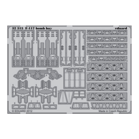
place from above, and glue the step tread 60 (etched
parts set) to it. The cover assembly should not be fixed
permanently, as the LEDs still have to be soldered to
the cables.


