Flomec QS200 User manual

QS200
Insertion Ultrasonic
Flowmeter
STANDARD METERS:
QS200-10, QS200-15, QS200-20, QS200-30, QS200-40
U.S. Design Patent No. D845,804 - Ultrasonic Insert
U.S. Design Patent No. D845,805 - Tee Housing for Ultrasonic Insert
NSF CERTIFIED METERS:
QS200-10PW, QS200-15PW, QS200-20PW, QS200-30PW, QS200-40PW
STANDARD RETROFIT INSERT:
QS200
Product Owner’s Manual EN
920901-01 Rev C04/29/2019
www.GlobalTestSupply.com
Find Quality Products Online at: sales@GlobalTestSupply.com

Please save these instructions for future reference. Read carefully before attempting
to assemble, install, operate or maintain the product described.
Protect yourself and others by observing all safety information. Failure to comply
with instructions could result in personal injury and/or property damage.
Please refer to back cover for information regarding this product’s warranty and
other important information.
SAVE FOR YOUR RECORDS
Model #: ___________________
Serial #: ___________________
Purch. Date: _______________
www.GlobalTestSupply.com
Find Quality Products Online at: sales@GlobalTestSupply.com
3
SAFETY /
SPECIFICATIONS
ASSEMBLY /
INSTALLATION OPERATION TROUBLESHOOTING MAINTENANCE /
REPAIR
GETTING STARTED
BEFORE YOU BEGIN
Usage Requirements
• This meter is for use with water only.
• This meter is not legal for trade applications.
• This meter has a permanent factory setting for measuring water only.
Power Source Requirements
• This meter requires DC power from a customer-provided controller in
order to provide flow information back to the controller.
Tools and Materials Needed
• Wire strippers, wire cutters, screwdriver, tape measure
• PVC pipe fittings (as needed), PVC pipe primer, PVC pipe cement
• Direct burial wire splices, valve box
• #18 AWG wire cable (Direct Burial) (Controller manufacturer may
recommend thicker guage wire for longer distances)
UNPACKING
Contents: QS200-10, -15, -20, -30, -40 or
QS200-10PW, -15PW, -20PW, -30PW, -40PW Meters
Note: The “PW” suffix denotes an NSF certified meter
(1) QS200 Ultrasonic insert assembly (2) K-factor Decals
(1) PVC Pipe Tee (for 1 in., 1-1/2 in., 2 in., 3
in., or 4 in. diameter pipe)
(1) Owners Manual
(1) Quick Release Pin
Contents: QS200 Retrofit Insert (Not available as NSF certified)
(1) QS200 Ultrasonic insert assembly (1) Quick Release Pin
(1) Set of two O-rings (round profile) (1) Owners Manual
(2) K-factor Decals
Inspect
• After unpacking the unit, inspect carefully for any damage that may
have occurred during transit. Check for loose, missing or damaged
parts. Shipping damage claims must be filed with carrier.
• See General Safety Instructions, and all Cautions, Warnings, and
Dangers as shown.
tools.eps
box.eps
magnify_2.eps
warning symbol.eps
measure.eps
plug.eps
oil.eps
megaphone.eps
biohaz.eps
Battery_Caution1.eps
Caution.eps
Crush_Caution1.eps
Electrical_Caution.eps
Face_protection.eps
Fall_Hazard.eps
Fall_protection.eps
GearHand_Hazard.eps
Head_protection.eps
Heavy_Hazard.eps
Hot_surface.eps
Recycle.eps
Resp_protection1.eps
Resp_protection2.eps
Temp_Caution1.eps
body_protection.eps
chemical_Caution.eps
ear_protection1.eps
explosive_caution.eps
eye_protection1.eps
foot_protection.eps
hand_protection.eps
www.GlobalTestSupply.com
Find Quality Products Online at: sales@GlobalTestSupply.com

MAINTENANCE /
REPAIR TROUBLESHOOTING OPERATION ASSEMBLY /
INSTALLATION GETTING STARTED
4
SAFETY /
SPECIFICATIONS
GENERAL SAFETY INSTRUCTIONS
IMPORTANT: It is your responsibility to:
• Ensure that all equipment operators have access to adequate
instructions concerning safe operating and maintenance procedures.
This product is not approved for use with
petroleum products (diesel fuel, unleaded
gasoline, jet fuel, kerosene, etc.), aromatic hydrocarbons or other
incompatible chemicals
This product is not approved for use in hazardous
locations.
When applying power, adhere to specifications
listed in appropriate electronics manual.
Disconnect external power before attaching or
detaching input or output wires.
NOTE: Be sure O-rings and seals are kept in good repair.
Compatibility of this product’s material and the
process fluid and/or environment should be
considered prior to putting into service.
Product should never be operated outside its
published specifications for temperature or
pressure. See specifications for your model.
Make sure flow and pressure have been eliminated
from process pipe prior to installing or removing
product.
Installation near high electromagnetic fields and
high current fields is not recommended and may
result in inaccurate readings.
Do not allow water to freeze in meter. Ice
expansion may burst the plastic housing.
Do not allow this meter to be used with steam.
www.GlobalTestSupply.com
Find Quality Products Online at: sales@GlobalTestSupply.com

5
GETTING STARTED ASSEMBLY /
INSTALLATION OPERATION TROUBLESHOOTING MAINTENANCE /
REPAIR
SAFETY /
SPECIFICATIONS
INSERTS - ALL METER SIZES
Transducer Excitation
OFF State Current 200µA (typical)
OFF State V-High Supply Voltage - (OFF State
Current * Supply impedance)
ON State Current (Supply Voltage / (Supply
impedance + 50Ω))
ON State V-Low ON State Current * 50Ω
Output Frequency 0 to 100 Hz
Output Pulse Width 4mSec (Approx.)
SPECIFICATIONS
QS200-10 QS200-15 QS200-20 QS200-30 QS200-40
QS200-10PW QS200-15PW QS200-20PW QS200-30PW QS200-40PW
Tee Housing
Material SCH 80 PVC (Polyvinyl chloride)
Insert
Housing
Material
PPS (Polyphenylene sulde) / ULTEM® (Polyetherimide)
Type Ultrasonic Flowmeter
Powered by
DC power provided by customer controller
7.5V (dc) min to 36V (dc) max
OFF State Current: 200μA (typical)
Unit of
Measure Controller Dependant
Flow Rate
0.22-33 GPM
0.83-124.92 L/min
0.1-15 ft/sec
0.55-82 GPM
2.08-310.41 L/min
0.1-15 ft/sec
0.92-138 GPM
3.48-522.39 L/min
0.1-15 ft/sec
2.06-309 GPM
7.80-1169.70 L/min
0.1-15 ft/sec
3.58-537 GPM
13.55-2032.78 L/min
0.1-15 ft/sec
Accuracy +/- 2% of Reading
Uncertainty 0.04 GPM
0.018 ft/sec
0.10 GPM
0.018 ft/sec
0.17 GPM
0.018 ft/sec
0.37 GPM
0.018 ft/sec
0.65 GPM
0.018 ft/sec
Max.
Working
Pressure
150 PSI @ 70°F (10.3 bar @ 60°C)
Operating
Temperature +32°F to +140°F (0°C to +60°C)
Storage
Temperature +32°F to +140°F (0°C to +60°C)
Field
Calibration No
Inlet / Outlet
Connections
1 in. Female
Socket
1 1/2 in.
Female
Socket
2 in. Female
Socket
3 in. Female
Socket
4 in. Female
Socket
Weight 0.95 lbs.
(0.43kg)
1.12 lbs.
(0.51kg)
1.39 lbs.
(0.63kg)
2.52 lbs.
(1.14kg)
3.21 lbs.
(1.46kg)
www.GlobalTestSupply.com
Find Quality Products Online at: sales@GlobalTestSupply.com
MAINTENANCE /
REPAIR TROUBLESHOOTING OPERATION ASSEMBLY /
INSTALLATION GETTING STARTED
6
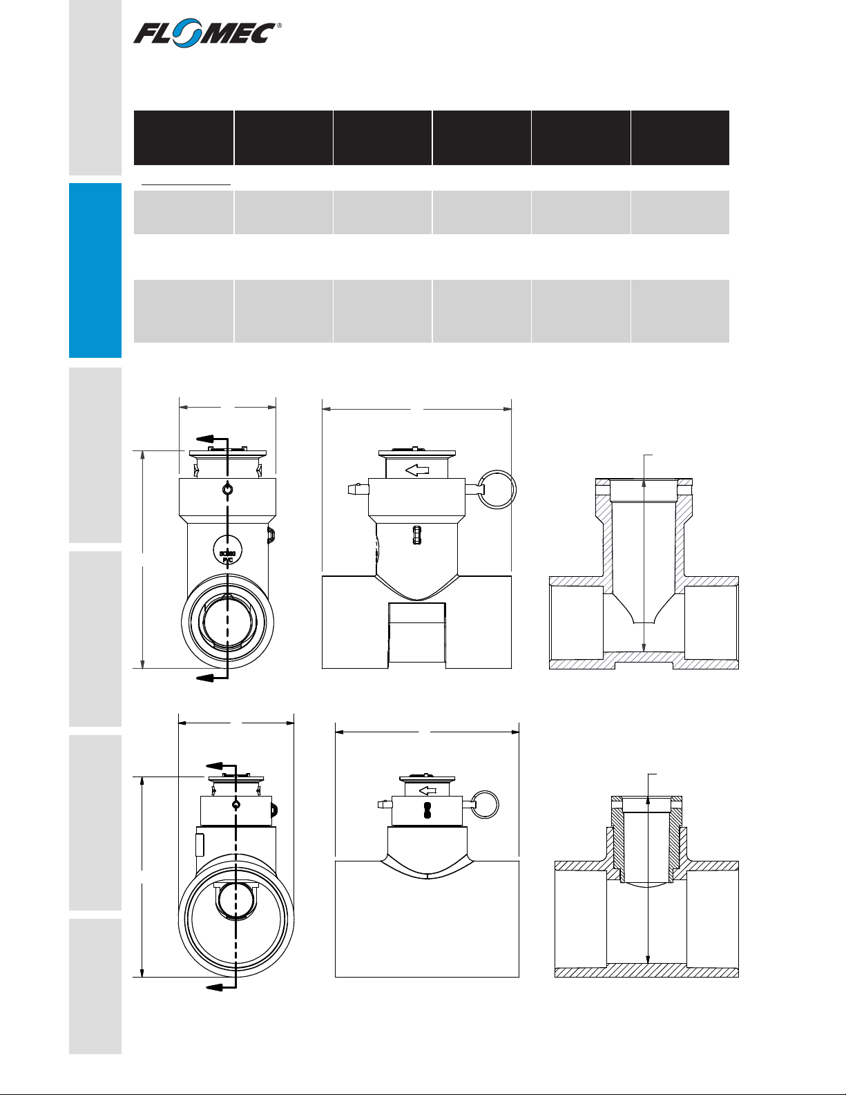
SPECIFICATIONS (CONTINUED)
QS200-10,
QS200-10PW
1 INCH
QS200-15,
QS200-15PW
1-1/2 INCH
QS200-20,
QS200-20PW
2 INCH
QS200-30,
QS200-30PW
3 INCH
QS200-40,
QS200-40PW
4 INCH
Dimensions
A. Length 4.25 in.
(108mm)
4.90 in.
(124mm)
5.56 in.
(141mm)
6.63 in.
(168mm)
7.38 in.
(187mm)
B. Height 5.38 in.
(137mm)
5.63 in.
(143mm)
6.12 in.
(156mm)
7.20 in.
(183mm)
8.41 in.
(213mm)
C. Width
(at widest
point)
2.50 in.
(64mm)
2.50 in.
(64mm)
2.88 in.
(73mm)
4.18 in.
(106mm)
5.23 in.
(133mm)
D. Depth 4.47 in.
(114mm)
4.47 in.
(114mm)
4.94 in.
(125mm)
4.91 in.
(124mm)
6.17 in.
(156mm)
SAFETY /
SPECIFICATIONS
Figure 1
PAGE 6, FIGURE 1 ADDITION
FOR 3" & 4" METERS
SECT
SECT
B
CA
SECT VIEW
(TEE ONLY)
D
For 3 in. & 4 in. Meters
A
SECT VIEW
(TEE ONLY)
D
PAGE 6, FIGURE 1
PICTORIAL UPGRADE (PIN)
FOR 1", 1 1/2", 2" METERS
B
C
SECT
SECT For 1 in., 1-1/2 in., & 2 in. Meters
www.GlobalTestSupply.com
Find Quality Products Online at: sales@GlobalTestSupply.com
7
GETTING STARTED ASSEMBLY /
INSTALLATION OPERATION TROUBLESHOOTING MAINTENANCE /
REPAIR
SPECIFICATIONS (CONTINUED)
K-Factor Information
NOTE: The meter size is molded on the vertical arm of the Tee
FLOMEC ultrasonic meters use K-factor plus offset numbers for greater
accuracy during calibration. These values are derived by calibrating the
meters using NIST traceable instrumentation. Using both sets of values to
calibrate the meters provides greater accuracy than using only a K-factor
value. The K-factor and offset values for each meter are listed below.
IMPORTANT: The K-factors provided are for reference. Accuracy can
be affected by plumbing configuration, fluid condition, adjoining pipe
schedule, type of meter tee (if using QS200 insert in non-FLOMEC tee),
and entrapped air. Customers should always validate accuracy and adjust
K-factor as needed.
Meter
Model Size
FLOMEC TEE
K-Factor
(frequency)
Offset
NON-FLOMEC TEE
K-Factor
(frequency)
QS200-10 1 in. 0.5386 0N/A
QS200-15 1-1/2 in. 0.7926 00.7947
QS200-20 2 in. 1.3765 01.3583
QS200-30 3 in. 3.8444 04.2505
QS200-40 4 in. 7.1676 07.2229
SAFETY /
SPECIFICATIONS
NSF CERTIFICATION INFORMATION
NOTE: QS200 meter are available as a standard meter, or as an
NSF certified meter. Only QS200 meters ordered as a complete unit
(ultrasonic insert installed in FLOMEC tee) qualify to be NSF certified.
Standard meter: The identification plate on the top of the ultrasonic
insert is marked “QS200”.
NSF certified meter: The identification plate on the top of the
ultrasonic insert is marked “QS200PW”, and the tee body is marked
with an NSF certification decal for additional identification.
NOTE: NSF certified meters use the same part number structure as
non-NSF models, except for the addition of the “PW” suffix on the end.
The “PW” suffix indicates an NSF certified meter. e.g., QS200-15PW.
NSF certification is valid only
when product is marked per
above information.
www.GlobalTestSupply.com
Find Quality Products Online at: sales@GlobalTestSupply.com

8
MAINTENANCE /
REPAIR TROUBLESHOOTING SAFETY /
SPECIFICATIONS GETTING STARTEDOPERATION ASSEMBLY /
INSTALLATION
INSTALLATION
Below is a typical QS200 meter with labeled components. Familiarize
yourself with the meter before installation.
Figure 2
TEE
QUICK RELEASE
PIN
INSERT ASSY.
BLACK WIRE RED WIRE
GREEN LED AMBER LED
SIZE INFO
I.D. PLATE WITH
SERIAL NUMBER
AND FLOW ARROW
TYPICAL QS200 METER
PAGE 8
www.GlobalTestSupply.com
Find Quality Products Online at: sales@GlobalTestSupply.com

9
GETTING STARTED OPERATION TROUBLESHOOTING MAINTENANCE /
REPAIR
SAFETY /
SPECIFICATIONS
ASSEMBLY /
INSTALLATION
INSTALLATION (CONTINUED)
Provide a straight pipe run of at least 10Xs the pipe’s diameter upstream of
the meter, and at least 5Xs the pipe’s diameter downstream of the meter.
The arrow embossed on the insert body denotes the flow direction.
FLOW DIRECTION
10Xs
5Xs
DOWNSTREAM UPSTREAM
INSTALL AT
ANGLE, IF
POSSIBLE
PAGE 8
INSERT
TOP VIEW
FLOW DIRECTION
ARROW
Figure 3
Install Meter Onto Pipe
NOTE: There is no need to remove the insert to install the meter. The meter
must be installed with the arrow on the insert pointing in the flow direction.
If the meter is accidentally installed backwards, simply remove the insert,
rotate 180 degrees so the arrow points in the flow direction, and reinstall the
insert.
The Tee is bidirectional, the insert is not. The insert operates correctly as
long as the insert arrow is pointed in the direction of flow. The insert can be
rotated 180 degrees, so its arrow can always be pointed in the direction of
flow regardless of Tee installation.
If space allows, install Tee / insert at an angle rather than pointing up
(see Figure 3).
NOTE: For 1 inch pipe installations, this angle is especially important and
should be set at 45 degrees for most accurate meter operation.
www.GlobalTestSupply.com
Find Quality Products Online at: sales@GlobalTestSupply.com

MAINTENANCE /
REPAIR TROUBLESHOOTING OPERATION SAFETY /
SPECIFICATIONS GETTING STARTED
10
ASSEMBLY /
INSTALLATION
INSTALLATION (CONTINUED)
1. Remove all burrs from the pipe ends I.D. and O.D. edges and the Tee
sockets I.D. edges (see Figure 4).
2. Clean and apply primer to the pipe ends and Tee sockets
(see Figure 5).
3. Apply PVC cement to pipe ends and Tee sockets and quickly
assemble the parts while the cement is fluid. Follow the cement
manufacturer’s instructions (see Figure 6).
4. Hold the cemented parts together for at least 30 seconds.
Figure 4 Figure 5
APPLY PRIMER
APPLY CEMENT
REMOVE BURRS
Figure 6
For Below Ground Installation
1. Install a valve box around the insert. Valve box extensions may be
needed depending on depth (see Figure 7).
NOTE: A minimum of 10 in. thick layer of gravel should be installed
immediately below the meter and valve box.
PAGE 9
Figure 7
www.GlobalTestSupply.com
Find Quality Products Online at: sales@GlobalTestSupply.com

11
GETTING STARTED SAFETY /
SPECIFICATIONS OPERATION TROUBLESHOOTING MAINTENANCE /
REPAIR
ASSEMBLY /
INSTALLATION
INSTALLATION (CONTINUED)
Wiring Connections
NOTE: Wiring diagram is shown in next section.
1. When using 18 AWG cable, cut off the unused wires so that they are
even with the sheath of the cable.
NOTE: For 18 AWG connections, remember the color of the twisted pair of
wires you use so that you can make an identical connection with the same
wires later.
2. 3M DBR/Y-6 Splice Kit Instructions:
Figure 8a
Figure 8c
Figure 8b
Figure 8d & 8e
www.GlobalTestSupply.com
Find Quality Products Online at: sales@GlobalTestSupply.com
12
MAINTENANCE /
REPAIR TROUBLESHOOTING SAFETY /
SPECIFICATIONS GETTING STARTEDOPERATION ASSEMBLY /
INSTALLATION
INSTALLATION (CONTINUED)
a. Strip insulation ¾ in. (19 mm).
b. With wire ends even, insert wires into the connector and tighten until
secure.
c. Insert the connector all the way into the tube until the connector rests
on the bottom of the tube.
NOTE: If having difficulty getting the twist-on connector down into the tube
when using small gauge wires, use a thin, non-conductive object to push
the connector to the bottom of the tube. Upon removal of the object, ensure
that no voids or water paths remain in the grease.
d. Fold the wires into the channels.
e. Close the cap.
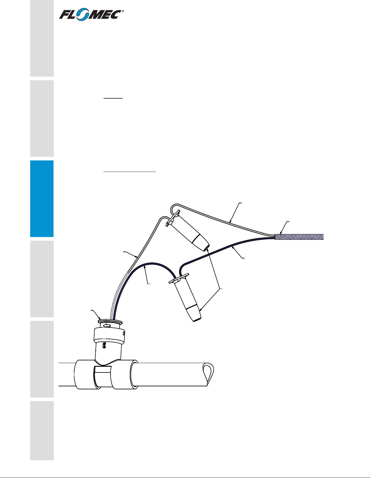
Wiring Diagram
This diagram shows connection to a RAINBIRD®Flow Smart Module.
Connections to other flow controllers may vary.
1212
RED
BLACK
DBR/Y-6
SPLICE KIT
FLOW INSERT
TO FLOW " + "
ON FLOW SMART
MODULE
TO FLOW " - "
ON FLOW SMART
MODULE
18 AWG CABLE
to CONTROLLER
Figure 9
www.GlobalTestSupply.com
Find Quality Products Online at: sales@GlobalTestSupply.com
14
MAINTENANCE /
REPAIR TROUBLESHOOTING SAFETY /
SPECIFICATIONS GETTING STARTED
OPERATION
Each QS200 meter is shipped with two K-factor decals (placed loose inside
the owner’s manual packet). One is to affix on or near the installed meter for
on-site use if desired. The other decal is to affix to a convenient spot on or
near the controller for immediate reference if desired.
LEDs Functionality
There are two LEDs on the QS200 product. The GREEN LED is used
to indicate basic power and functionality of the meter. The AMBER LED
is used to indicate that there is a flow of water through the QS200 meter
insert. The LEDs will behave in the following manner to indicate different
modes of operation:
MODE LED BEHAVIOR
Power Disconnected
or Meter Failure: Both GREEN and AMBER LEDs are OFF.
No Flow Low
Power Mode:
GREEN LED flashes ON/OFF at a rate
of approximately 2 blinks per second.
No Flow or Reverse
Flow Active Mode:
GREEN LED flashes ON/OFF at a rate
of approximately 8 blinks per second.
Low Flow
Active Mode:
GREEN LED flashes ON/OFF at a rate of
approximately 8 blinks per second and the
AMBER LED flashes ON/OFF at a rate that is
proportional to the rate of water flow thru the
meter.
**High Flow
Active Mode:
GREEN LED flashes ON/OFF at a rate of
approximately 8 blinks per second and the
AMBER LED will appear to be constantly ON, but
will be dim.
**NOTE: To save power it is normal for the LEDs to be dim when flashing at
higher flow rates. At very high flow rates, the AMBER LED will appear to be
constantly ON but dim.
1414
ASSEMBLY /
INSTALLATION
OPERATION
www.GlobalTestSupply.com
Find Quality Products Online at: sales@GlobalTestSupply.com
15
GETTING STARTED TROUBLESHOOTING
SAFETY /
SPECIFICATIONS
1515
ASSEMBLY /
INSTALLATION OPERATION MAINTENANCE /
REPAIR
TROUBLESHOOTING
1. The LEDs are the primary indicators of meter performance. Refer to
the Operations Section for LED indicating functionality.
2. Entrained air is air bubbles suspended in the water flow. Entrained
air creates errors in accuracy of ultrasonic technology meters.
Recommend a maximum of 10% entrained air in the water flow.
3. The faces of the transducers need to be clean and free of oily
substances for accurate operation. Do not touch transducers with
fingers, oily rags, etc.
DO NOT use wire brushes or abrasives to clean the faces of the
transducers (see Figure 10).
4. Ensure the flow direction arrow is pointing in the direction of flow for
correct LED functionality.
5. Ensure the quick release pin is installed in the tee to maintain pressure
and alignment of the insert in the tee.
Figure 10
TRANSDUCER
FACES
GOES ON PAGE 13
www.GlobalTestSupply.com
Find Quality Products Online at: sales@GlobalTestSupply.com

REPAIR
QS200 Insert Replacement and
QS200 Retrofit Insert Installation Instructions
NOTE: These instructions are intended to assist in replacing the insert in an
existing FLOMEC®QS200 ultrasonic Meter.
These instructions also apply when a FLOMEC QS200 insert is used as
a replacement insert in other brands of Tee type meters, that have an
obsolete or unreliable insert.
The FLOMEC QS200 is a direct replacement for a paddle wheel type insert
in most meters that have a Tee type housing.
Keep the new insert free of dirt and debris during
installation.
Check Meter Size
If your flow controller requires a meter K-factor, use the K-factor for your
size meter (see SPECIFICATIONS section). If the meter size is unknown, it
is easily determined using one of the following methods (for FLOMEC and
other brands):
1. Dipstick Method (For 2 in., 3 in. and 4 in. meters only):The interior
depth of the meter body indicates its size. To check, remove the old
insert from the meter body and insert the end of a stiff tape measure
down into the insert bore until it touches the bottom of the meter body
bore. Read the depth shown on the tape measure at the top of the
Tee housing (see Figure 11) and compare with dimension “D” in the
specifications section (see Figure 1).
2. Line Pipe Size Method: Normally, the line pipe size is the same as the
meter size. Figure 12 shows line pipe sizes.
NOTE: FLOMEC Tees are marked with hallmark of size, part number,
SCH80 and pressure.
MAINTENANCE /
REPAIR TROUBLESHOOTING OPERATION ASSEMBLY /
INSTALLATION
SAFETY /
SPECIFICATIONS GETTING STARTED
16
Figure 11
www.GlobalTestSupply.com
Find Quality Products Online at: sales@GlobalTestSupply.com

REPAIR (CONTINUED)
GETTING STARTED SAFETY /
SPECIFICATIONS
ASSEMBLY /
INSTALLATION OPERATION TROUBLESHOOTING MAINTENANCE /
REPAIR
1.315
[1 5/16]
Ø
1.900
[1 29/32]
Ø
2.375
[2 3/8]
Ø
LINE PIPE SIZES
1" PIPE
1 1/2" PIPE
2" PIPE
3" PIPE
4" PIPE
3.500
[3 1/2]
Ø
4.500
[4 1/2]
Ø
Figure 12
17
www.GlobalTestSupply.com
Find Quality Products Online at: sales@GlobalTestSupply.com

TROUBLESHOOTING OPERATION ASSEMBLY /
INSTALLATION
SAFETY /
SPECIFICATIONS GETTING STARTED
MAINTENANCE /
REPAIR
REPAIR (CONTINUED)
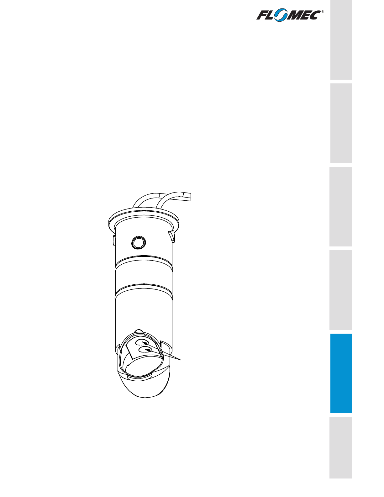
Remove Old Insert From Tee
1. Clean all dirt and debris away from the immediate area of the old insert
and the top of the meter, then pull out the quick release pin from the
meter (see Figure 13).
2. Remove the old insert. Grasp the insert flange with your hand and pull
straight up and out of the Tee, making sure no dirt or other particles fall
into the insert bore of the meter (see Figure 14).
NOTE: The FLOMEC Multi-Tool (p/n 146055-501) can be used to make
removal of old insert easier (see Figure 17).
NOTE: When replacing another manufacturer’s insert with the QS200
Retrofit Insert, the old insert could have a sediment or mineral buildup and
need to be leveraged out of the tee.
18
PAGE 9 & 17
PAGE 16 & 17
Figure 13 Figure 14
www.GlobalTestSupply.com
Find Quality Products Online at: sales@GlobalTestSupply.com
GETTING STARTED SAFETY /
SPECIFICATIONS
ASSEMBLY /
INSTALLATION OPERATION TROUBLESHOOTING MAINTENANCE /
REPAIR
REPAIR (CONTINUED)
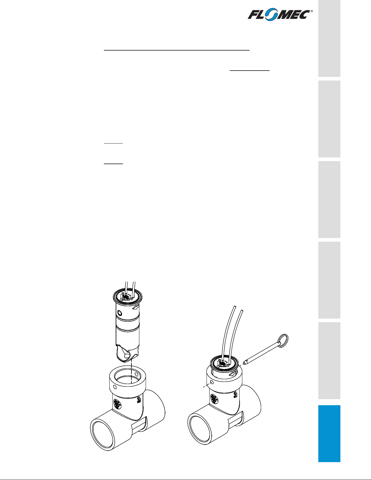
Install New or Replacement Insert Into Tee
1. The Tee insert bore must be clean before installing the insert and the
(2) black O-rings on the insert should be fully lubricated.
2. Orient the insert over the insert bore so that the arrow on the insert is
pointing in the direction of flow.
3. Insert the insert straight down into the Tee.
4. Push down on the insert flange and twist slightly to install, and to
align the retaining pin holes in the insert with the holes in the Tee (see
Figure 15).
NOTE: The FLOMEC Multi-Tool (p/n 146055-501) can be used to make
installing new insert easier (see Figure 18).
NOTE: The O-rings on the outside of the QS200 Retrofit Insert are square
profile O-rings. When installing in another brand of Tee, if the insert fits
too tight into the Tee, replace the square profile O-rings with the round
profile O-rings included with the QS200 Retrofit Insert. Their installation
could make installation easier in tight fitting Tees. The O-rings must be fully
lubricated before insert installation.
5. Next, replace the quick release pin (see Figure 16).
6. Using the splicing and wiring information (see WIRING
CONNECTIONS and WIRING DIAGRAM in the INSTALLATION
section), connect the wiring from the new insert to the wiring cable of
the controller.
7. Energize the insert and verify that it is operating properly (see
Troubleshooting section if required).
19
PAGE 9 & 17
PAGE 16 & 17
Figure 15 Figure 16
www.GlobalTestSupply.com
Find Quality Products Online at: sales@GlobalTestSupply.com

TROUBLESHOOTING OPERATION ASSEMBLY /
INSTALLATION
SAFETY /
SPECIFICATIONS GETTING STARTED
MAINTENANCE /
REPAIR
REPAIR (CONTINUED)
Using the FLOMEC Multi-Tool
The multi-tool was designed exclusively for tee type meters that use an
insertion type insert. It facilitates easier removal of the insert, whether from
a QS200 meter or other brands of tee type insertion meters.
It is especially useful when attempting to remove an old, inoperative,
or inaccurate insert from another brand of tee type insertion meter for
replacement with a QS200 insert.
The multi-tool is versatile, compact and fits easily into the valve box for
close quarters use.
The pointed end is designed for use as:
1. A versatile pry bar and driving wedge. On other brands of tee type
insertion meters, when the insert lip may be too close to the top of the
tee to use the U-formed end of the multi-tool, use the pointed end (as
pry bar or driving wedge) between the insert lip and top of the tee to
break the insert loose and gain room between the insert lip and tee to
use the U-formed end to lever the insert up and out.
2. An alignment tool to align the pin holes of the new insert with the pin
holes in the tee.
3. A cleaning tool for clearing debris from the valve box lid groove or
other crevices.
The U-formed end is designed for use as:
4. A handle for leverage when using the pointed end.
5. A levering tool by slipping the U-formed end around the insert between
the insert lip and the top of the tee. This positions the tool for use as a
lever for levering inserts up and out of the tee for replacement. It can
be levered up or down, and can be rotated to any quadrant around the
insert in order to give the best position for leverage.
The multi-tool (P/N 146055-501) is a separate item available to the
customer, and is listed in the repair parts list near the back of the manual.
20
www.GlobalTestSupply.com
Find Quality Products Online at: sales@GlobalTestSupply.com
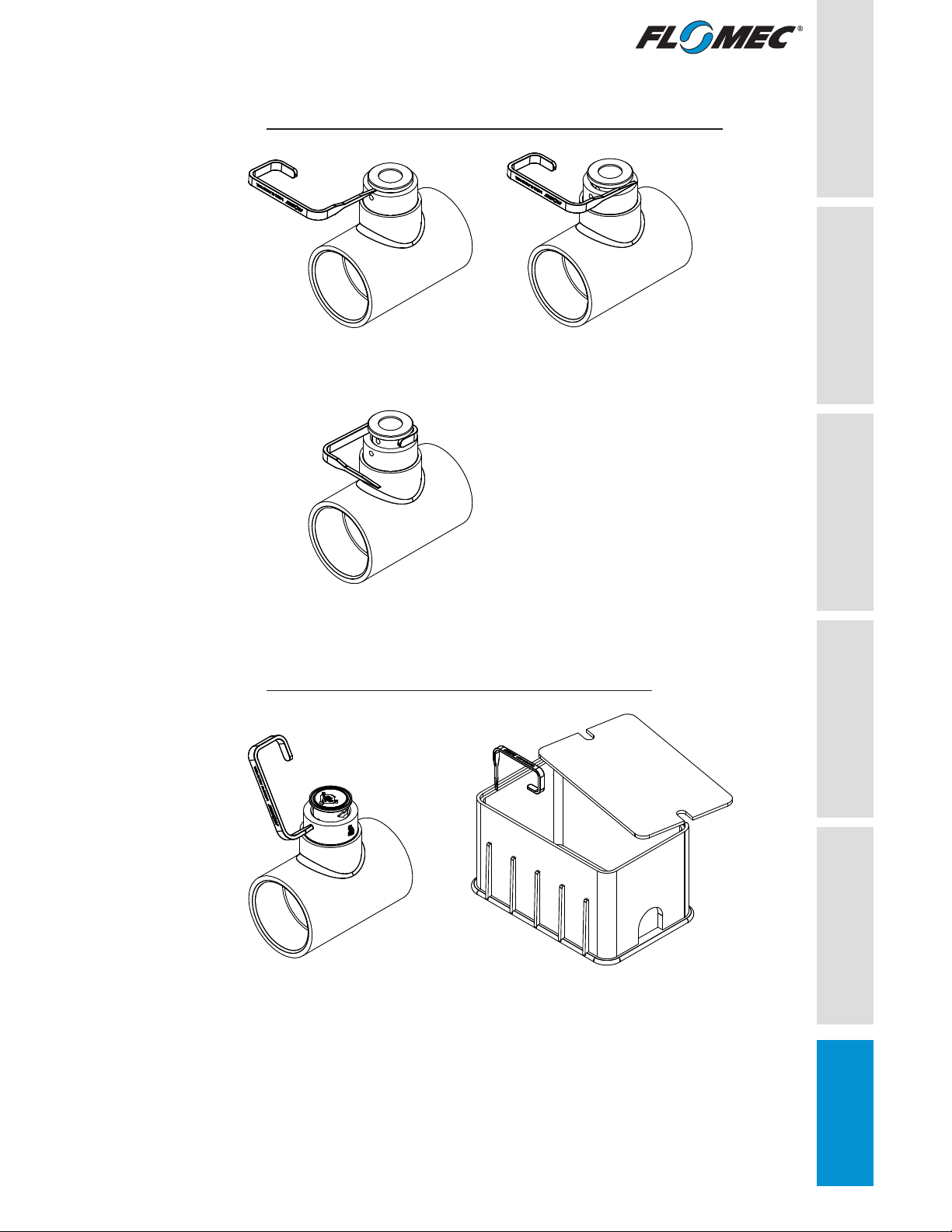
Figure 17
Figure 18
GETTING STARTED SAFETY /
SPECIFICATIONS
ASSEMBLY /
INSTALLATION OPERATION TROUBLESHOOTING MAINTENANCE /
REPAIR
REPAIR (CONTINUED)
Remove Old Insert From Tee with FLOMEC Multi-Tool
21
Install New QS200 Insert FLOMEC Multi-Tool
PRY UP - To break a stuck insert loose
LEVERAGE - To Lift insert up and out
PIN HOLE ALIGNMENT -
For easy pin install
CLEAN LID GROOVE -
Remove dirt, roots, debris
DRIVING WEDGE - To lift insert more
www.GlobalTestSupply.com
Find Quality Products Online at: sales@GlobalTestSupply.com
Other manuals for QS200
5
Table of contents
Other Flomec Measuring Instrument manuals

Flomec
Flomec G2 User manual

Flomec
Flomec QS200 User manual

Flomec
Flomec EGM Series User manual

Flomec
Flomec QSE Series User manual

Flomec
Flomec LM51DN User manual

Flomec
Flomec QSE Series User manual

Flomec
Flomec Q9 User manual

Flomec
Flomec QS100-10 User manual

Flomec
Flomec QS200 User manual

Flomec
Flomec D-40 User manual

Flomec
Flomec QS200 User manual

Flomec
Flomec G Series User manual

Flomec
Flomec GPRO QM Series User manual

Flomec
Flomec TM Series User manual

Flomec
Flomec 490 User manual

Flomec
Flomec OM025 User manual

Flomec
Flomec QSE Series User manual

Flomec
Flomec TM Series User manual

Flomec
Flomec Oval Gear User manual

Flomec
Flomec Q9 User manual


