Aerpro FP8419K User manual

FP8419K
Integrated Touch Screen Control Kit
for Ford Vehicles
APPLICATION
FEATURES
Ford Mustang 2015> (Right Hand Drive Models Only)
•Allows for the installation of a double DIN aftermarket stereo
•Replaces HVACcontrol unit
•Retains climate controls, steering wheelcontrols, heated seats, vehicle OE
personalisation menus and settings
•Accomodates OEM toggle or OEM push buttonswitches
•Includes mountingbrackets and fitting accessories
•Finished in gunmetal to match vehicle dashboard
The information provided in this document is subject to change without notice due to manufacturer changes and/or improvements to the product/s. This
instruction manual is based on documented data and research. The manufacturer of this product cannot be held responsible for any changes made to the
vehicle by the manufacturer or damages that may occur through the installation of this product in accordance with the steps outlined herein.
Note: Application data is subject to change at any time
DISCLAIMER
For vehicles with Concert,Chorusor Symphony factory stereo and Mini ISO connector
FP8419K_IG_en-GB_v1
1. Fascia Panel
2. Right Bracket
3. Left Bracket
4. Four Switch Trim
5. Back Cover
6. PCB Spacer
7. Pocket
RECOMMENDED TOOLS
•Panel Removal Tool •Screwdriver •Cutting Tool
2FP8419K_IG_en-GB_v1
PRIOR TO INSTALLATION
INSTALLATION GUIDE
Read the manualpriorto installation. Technical knowledgeis necessary for installation. The place of installation must be
free of moistureand away fromheat sources. Please ensure that the correct tools are usingduringthe installation to avoid
damageto the vehicle or product.Connects2 can not beheld responsible for the installation of this product.
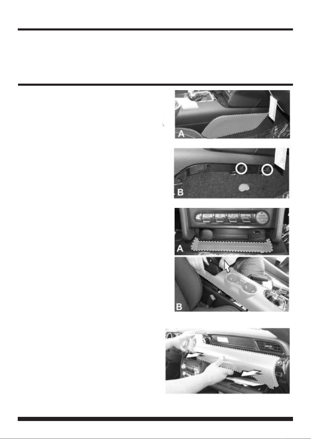
1. Remove the two (passenger and driver side) knee
panels on the lower console. (A)
Next,remove the two exposed screws (B)
2. Using a panel removal tool,carefully remove the
tray located below the USB and 12V socket ports,
then remove and retain the two exposedscrews.
Lift and slightly pull back the centre cup holder
console but do not remove the console.
3. Using a panel removal tool,carefully remove the
air vent trim surrounding the vents, temp and boost
control gauge. Unplug and remove.
*WARNING*
**DASH MODIFICATIONIS REQUIRED FOR FULL INSTALLATIONOF A DOUBLE DIN STEREO WHEN USING THIS PRODUCT**
See Step 7 for Details

3FP8419K_IG_en-GB_v1
INSTALLATION GUIDE
4. Unclip and remove the plastic plate located
inbetween the USB plug-inandthe cigarette lighter
5. Remove the four screws securing the OEM panel
to the dash (circled), then unplugand remove the
panel
6. Remove the OEM display and the CDreceiver by
unscrewing the four screws for each component,
then unplug all wiring and remove.
7. Carefully cut and remove the highlighteddashed
area on the sub-dashframe to create space for the
double DIN stereo.
File down the ridgedareas highlighted and noted in
the image.
NB: Only file downthe amountof plastic necessary to
achieve a ush t
**DASH MODIFICATION**

4FP8419K_IG_en-GB_v1
INSTALLATION GUIDE
8. Remove the ten screws and the 12V socket locat-
ed behindthe OEM climate control panel and retain
for installation. Then remove the PCB board back
cover.
NB: The amountof screws may vary between vehicle
models.
Retain the 12Vsocket fromthe OEM panel and place it
on the aftermarket panel once removedfrom the OEM
panel
9. Remove the ve screws securing the PCB board
to the panel, then remove from the panel
NB: The amountof screws may vary between vehicle
models
10. Lift and removethe plastic CD insert slot away
from its location

5FP8419K_IG_en-GB_v1
INSTALLATION GUIDE
11. Lift and remove the drive train/ignition controls
and rubberpad from the OEM panel and retain for
later install
NB: Remove rubberand plastics blockingpieces
needed in order to remove the ignition controls
12. Place the drive train/ignition control trim into
the fascia panel
13. Place the OEM drive train/ignitioncontrol
buttons (retained in Step 11) into the trim from
Step 12.
Next,place the three providedPCB spacers
indicated by the arrows on top of the button
controls.
NB: Image is for illustration purposes only and may not
represent the vehicle's exact ignition control button
configuration

6FP8419K_IG_en-GB_v1
INSTALLATION GUIDE
14.Place the rubberpad from the OEM drive train
controls onto the back of the buttons, being careful
not to knock over the spacers placed in the previous
step.
15. Carefully align the circuit board over the rubber
pad
16.Place the back cover plate over the PCB and
secure using the six screws retained in disassembly
NB: Use the screws attained fromthe OEM PCB cover
plate
7FP8419K_IG_en-GB_v1
INSTALLATION GUIDE
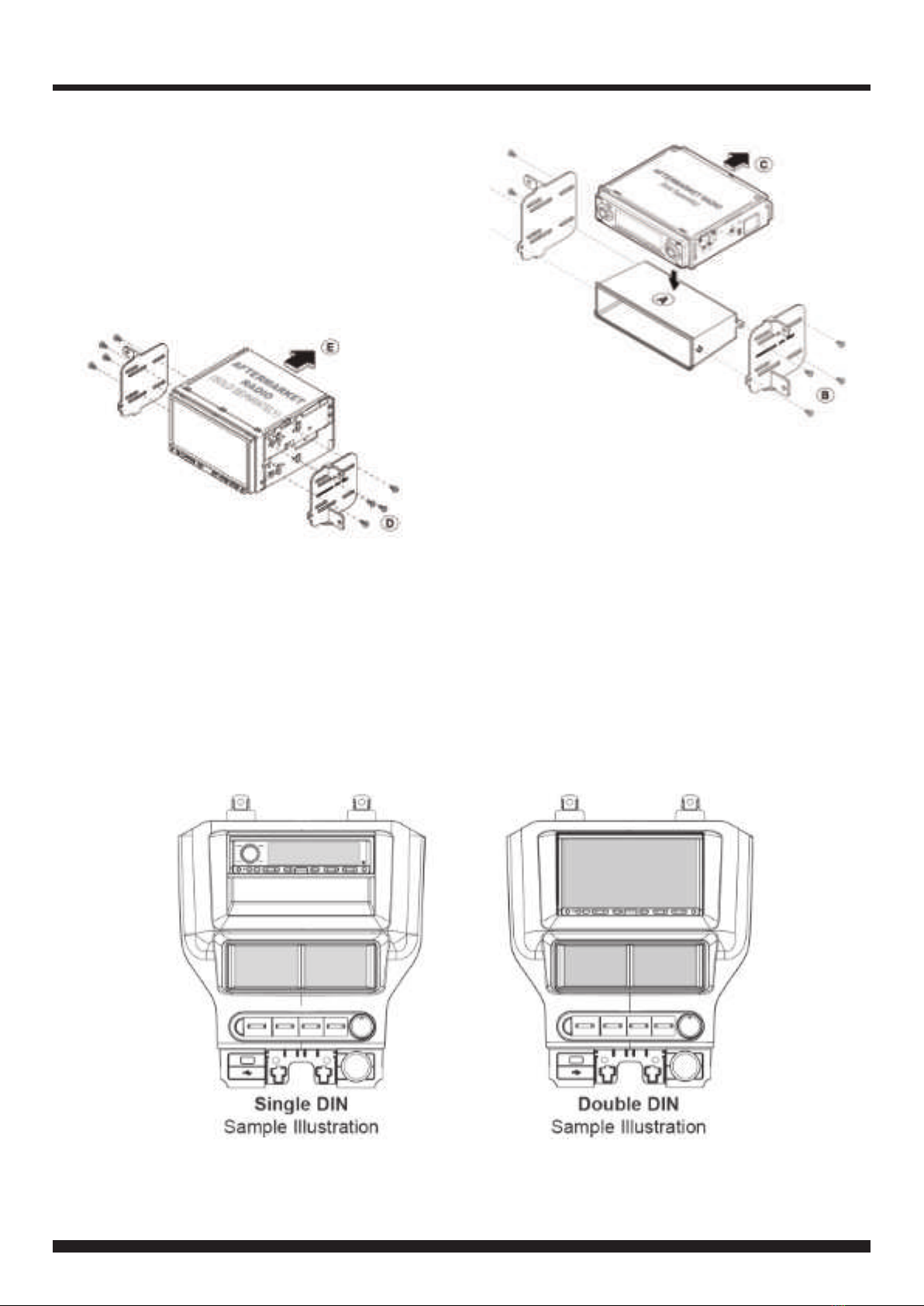
17. For Single DIN Installation:
Attach the brackets provided to the pocket (A), then
secure the stereo to the brackets (B). Lastly, secure
stereo assembly into dash cavity (C).
18. Connect and reassemble everything in the
reverse orderof disassembly to complete the
installation
NB: 12V/cigarette plugis retained fromOEM panel
For DoubleDIN Installation:
Attach the brackets provided to the aftermarket
stereo (D),then secure stereo assembly into dash
cavity (E).

8FP8419K_IG_en-GB_v1
CONNECTING THE PATCH LEAD
STEERING WHEEL CONTROL CONFIGURATION
1. Track -
2. Volume +
3. Track +
4. Volume -
5. Voice Command(For JVC/Alpine/
Pioneer Units with Vocie Command
Capabilities)
6. Mute
7. Hang Up (BT HU Only)
8. Pick Up (BT HU Only)
Here are some exampleof how to make various patch leads:
Example 1: Alpine -Cut Link J2, then use the Jack Connector
to connect the patch lead to the head unit
Example 2: Kenwood -Cut Link J1 and J2, then use the
wire connector to connect the patch lead to the head unit
9FP8419K_IG_en-GB_v1
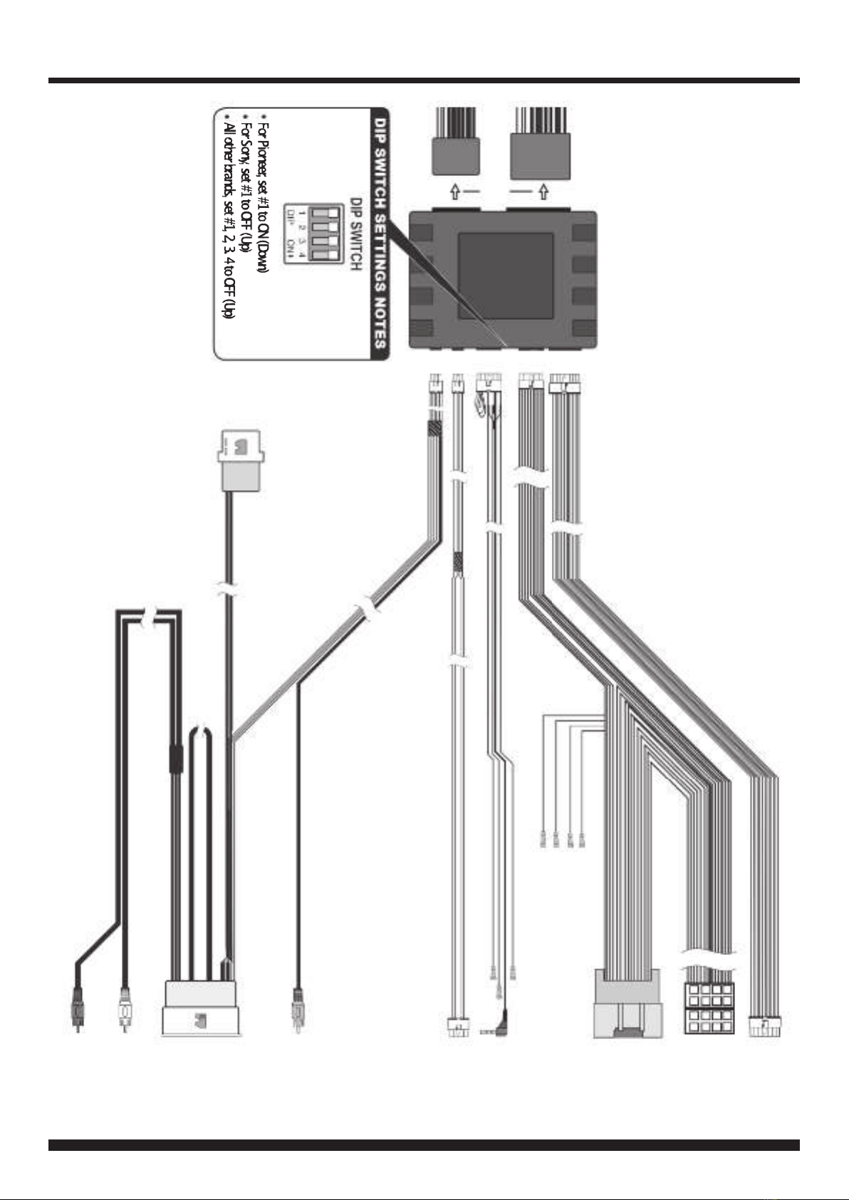
WIRING DIAGRAM
16Pin
10Pin
12Pin
4Pin
6Pin
To Back of
Push-Start
Module
To
Aftermarket
Stereo
To Vehicle
Harness
SWC
(See 'Connecting
the Patch Lead')
To Back of
ITC Display
Reverse
Video Input
(Brown)
To Vehicle
Harness
Behind
Screen
For Both
4.2" & 8"
Monitors
(Attach to
Sync Box)
Audio Aux
(White)
Audio Aux
(Red)
ToClimateControl
PanelHarness
12Pin Display
Connector
-NotUsed
Pink SpeedPulse
Lt. Green ParkBrake
Purple/White Reverse Gear
Mute

10 FP8419K_IG_en-GB_v1
CLIMATE/CONVENIENCE CONTROLS
The touchscreen interface replaces the factory climate, convenience andpersonalisation controls built into the factory Ford
stereo/dash panel. This solution provides improvedergonomics whilst addingtouchscreen capabilities uniqueto this sys-
tem. Read the followingsections to familiarise yourself with the operatingcontrols and settings.
LEFT TOUCHSCREEN BUTTONLAYOUT
1. Change on-screenbutton conguration to show
controls for heated and cooled seats (if vehicle is
equipped). Level for both driver and passenger side
seats can be adjusted up or down independently.
2. Access menu. See ʻMenu Structureʼ for more
information.
3. Quick press four times and hold to enable
Installer Menu. The Installer Menu can be foundun-
der ʻVehicle Settingsʼ by pressing the MENU
button (4) on the screen.
4. Press the POWER buttonto togglethe climate
controls on or o.
5. Press to toggle Automatic Air Conditioningon or
o (indicated by the orange icon).
6. Press to turn on Air Recirculation feature.
When on,air will be recirculated inside the vehicle
to quickly cool the interiorand prevent outside air
or odors from entering.
Note: Operatingthis function when the A/Cis off in-
creases humidityand may cause the windows to fog.
This feature is not available when Defrost orDefog
modesare active.
HH:MM
TEMP
MENU
CTRL
MyTemp
A
MAX
A
7. Activates maximumcooling with temperature
automatically adjusted to the lowest setting and fan
speed increased to the highest setting. Press the
button again to returnto the previously selected fan
speed and temperature setting.
8. A preset/favourite temperature for the driver zone
can be stored using the MyTemp function. Once a
desired temperature for the driver has been set, long
press/hold MyTemp button until a beep is heard. A
short press of the MyTemp button will now instantly
restore the preset driver temperature.
9. Press to direct air at the front windscreen to help
clear fog or moisture. A light will illuminate in the
buttonto indicate the active/inactive status of the
Defrost mode.
Note: For best results, clear the windowsof snow or ice
before activating Defrost mode.Donot attempt to
operate the vehicle until windows are clear.
10.Press to defog the rear window. A light will illumi-
nate in the button to indicate the active/inactive
status of the Defog mode. The Defog mode will also
be turnedo when the vehicle ignition is turned o.
3
2
1
8
10 9
7
6
5
4

11 FP8419K_IG_en-GB_v1
CLIMATE/CONVENIENCE CONTROLS
RIGHT TOUCHSCREEN BUTTONLAYOUT
11. Touch the vent control mode icons to select
desired vent mode.Graphics are displayed according
to the selected vent and airow pattern. Air can be
directed through the instrument panel, oor,side and
windsheild outlets as desired.
12.Select the desired temperature for the driver zone
by using the two arrow buttons.
13. Select the desired temperature for the passenger
zone by using the two arrow buttons.
14. Toggle ʻDual Modeʼ function to enable dierent
temperatures to be selected for driver and passenger
zones. Turno to lock both zones to identical tem-
peratures.
15. Increase fan speed using the Fan +button
23.0 22.0
DUAL
AUTO
AUTO
16. Decrease the fan speed using the Fan -button
17. Toggle ʻAUTOʼon to engage Auto mode for all
functions (Air Direction,Air Conditioning,Recircu-
lation, Fan Speed). Whilst in Auto mode,the vehicle
will try to reach the selected temperature in the most
ecient way possible.
Note: The ʻAUTOʼbutton will perform a different function
dependingon whether the climate controls are being
adjusted manually,semi-automatically,or fully automat-
ically.
If all functions are undermanual control,pressing
ʻAUTOʼwill activate full auto mode(all functions under
automatic control). If only some functions are under
manual control, then pressing ʻAUTOʼwill return all func-
tions to manual control. A second press of ʻAUTOʼwill
then activate full auto mode.
12
17
15 16
14
13
11
12 FP8419K_IG_en-GB_v1
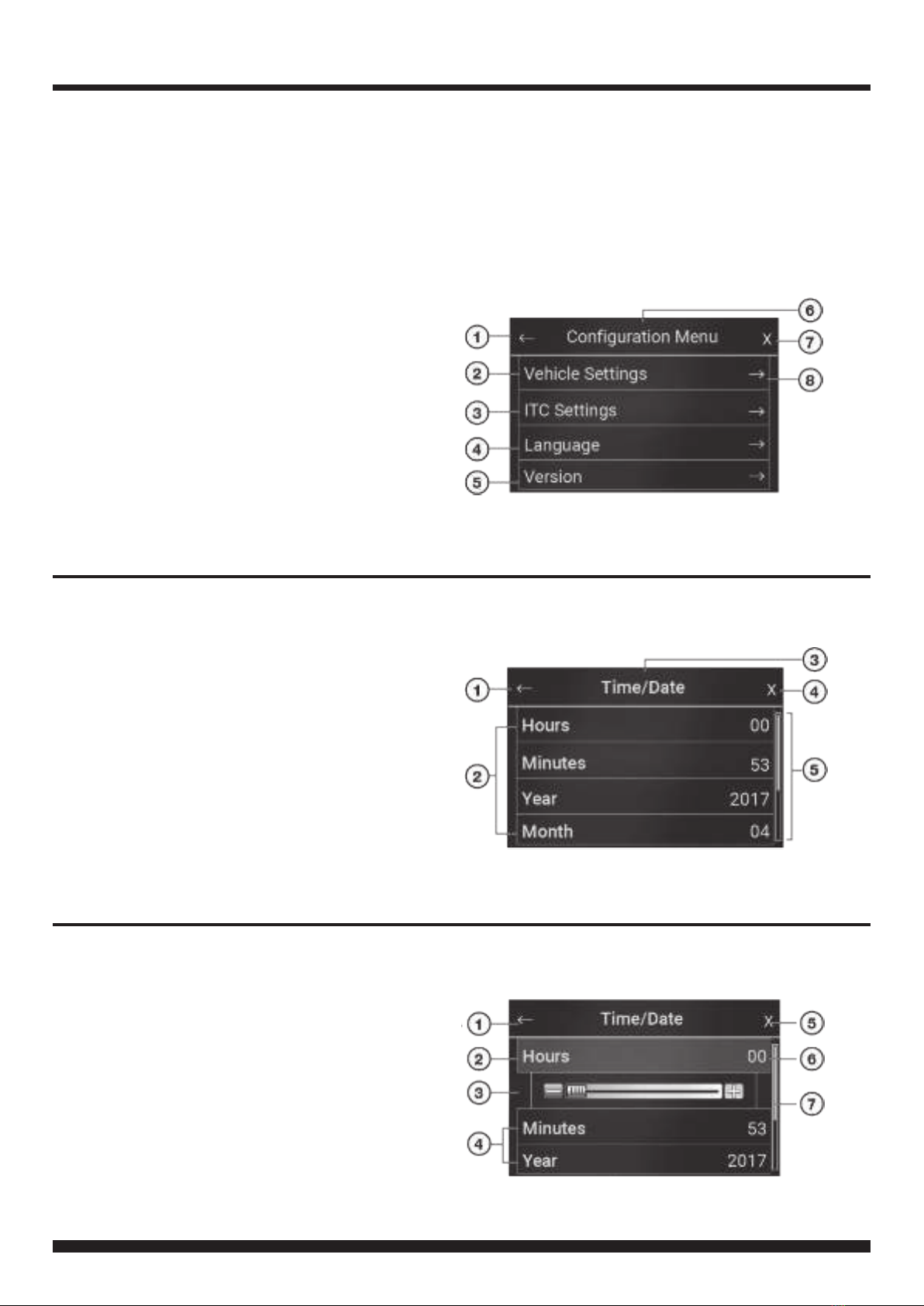
MENU NAVIGATION
Main Menu Navigation
1. Return to previous menu
2. Enter Vehicle Settings menu
3. Enter ITCSettings menu
4. Enter Languagemenu
5. Enter ModuleVersionmenu
6. Header
7. Close menu settings
8. Enter Sub-menufor selected option
Sub-MenuNavigation
1. Return to previous menu
2. Sub-menuconguration options
3. Header
4. Close menu
5. Scroll bar (Scroll Up/Downfor moreoptions)
Setting Configuration Options
1. Return to previous menu
2. Setting highlightedwhen selected
3. Scroll bar (Use to customisesetting)
4. Press to select option
5. Close menu
6. Current value (Adjust with slider)
7. Scroll bar (Scroll Up/Downfor moreoptions)
Press the MENU button to access the Configurationmenuand adjust Vehicle, ITC Interface, Language and
Version settings.
The following screenshots are sample menudisplays to assist in the navigation of the user interface. Use
the Return Arrow to go back to the previous menu. Press the X to close the menuwindow and return to the
TFT colour touch screen home screen. For further setting options, refer to the charts in the following pages
of this manual.

13 FP8419K_IG_en-GB_v1
VEHICLE CONFIGURATION SETTINGS CHART
VEHICLE SETTINGS (INSTALLER MENU)
Toaccess the Installer Menu,quick press the Menu icon on the touch screen display four times. A popup will
appear with the notification: "Installer Menu Enabled".
Use the charts on the following pages of this instruction manual to navigate throughthe various menusand
settings offered by the kit.
*Set 'CameraType'to 'Type2' for Mustang application to enable Zoomfeature. If Zoomfeature does not work,
select 'Type1'.
**Please note that an additional moduleis requiredin orderto retain the Shaker amplified system in vehicles
with this OEM option.
**

14 FP8419K_IG_en-GB_v1
ITC SETTINGS CHART
LANGUAGE & SOFTWARE SETTINGS CHART

15 FP8419K_IG_en-GB_v1
NOTES

16 FP8419K_IG_en-GB_v1
NOTES
Table of contents
Popular Automobile Electronic manuals by other brands

Peripheral Electronics
Peripheral Electronics PXDX-KD instruction manual

Audiovox
Audiovox Prestige 128-8602 installation manual

Paser
Paser PARKVIEW CF0006UNPS51 installation manual

Lexus
Lexus RX330 2005 Technical Service Information Bulletin

BFT
BFT Espas 20I installation manual

Mercedes-Benz
Mercedes-Benz COMAND Operator's manual


