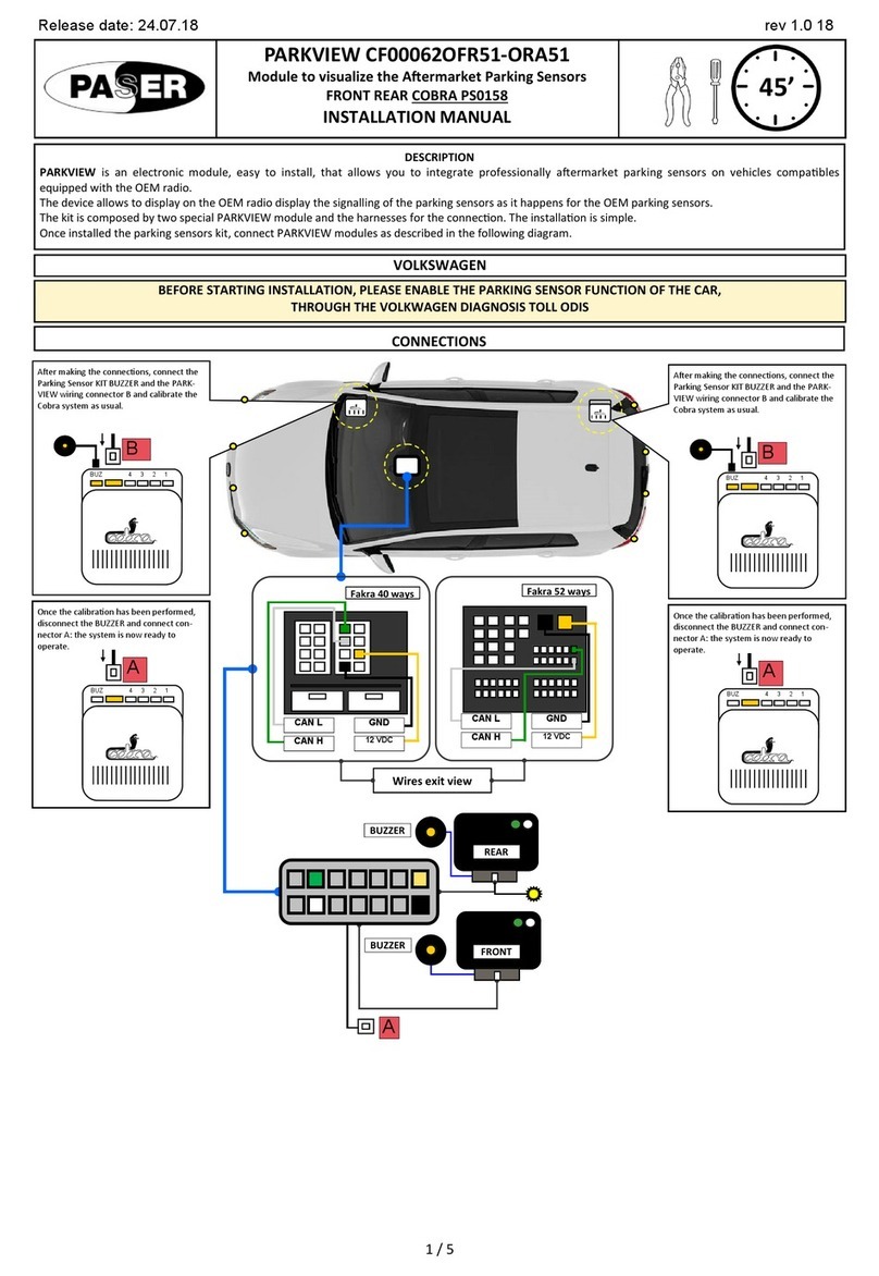
Paser PARKVIEW CF0006UNPS51 User manual

Release date: 24.07.18 rev 1.0 18
1 / 9
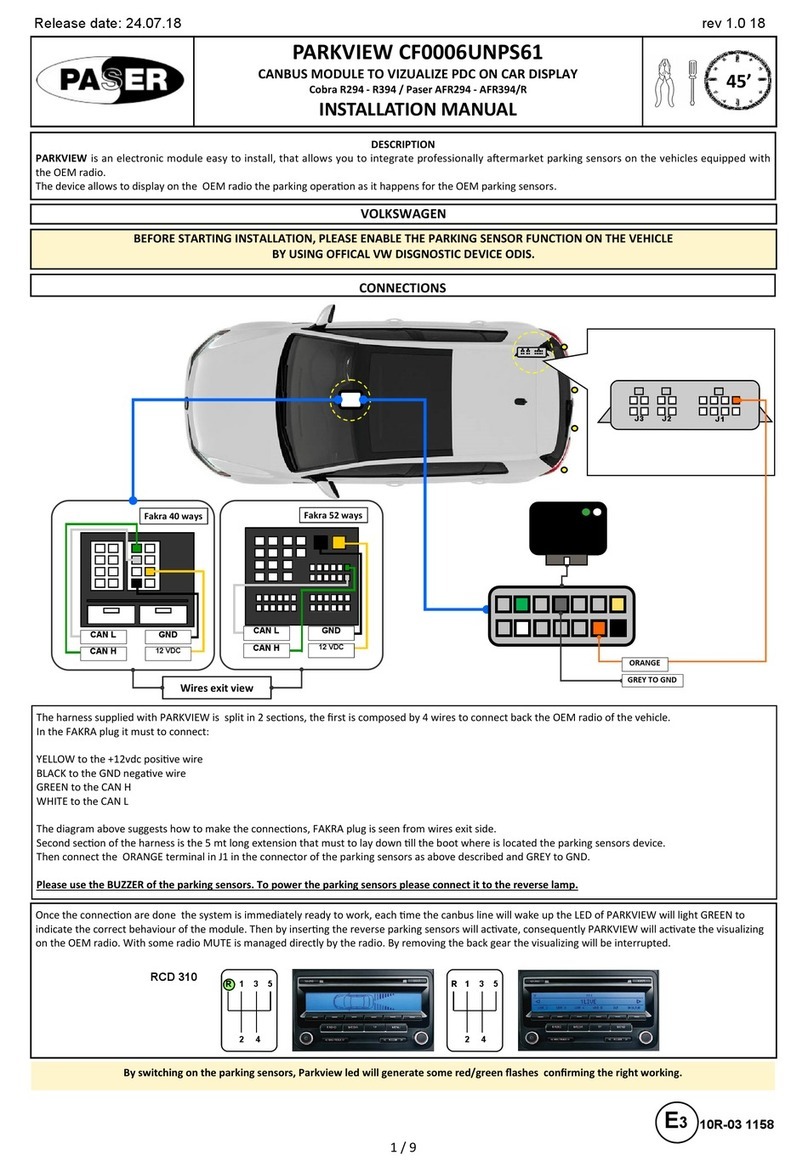
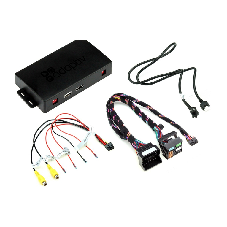
is an electronic module easy to install, that allows you to integrate professionally aermarket parking sensors on the vehicles equipped with
the OEM radio
The device allows to display on the OEM radio the parking opera"on as it happens for the OEM parking sensors
The harness supplied with PARKVIEW is split in 2 sec"ons, the first is composed by 4 wires to connect back the OEM radio of the vehicle
In the FAKRA plug it must to connect:
YELLOW to the +12vdc posi"ve wire
BLACK to the GND nega"ve wire
GREEN to the CAN H
WHITE to the CAN L
The diagram above suggests how to make the connec"ons, FAKRA plug is seen from wires exit side
Second sec"on of the harness is the 5 mt long extension that must to lay down "ll the boot where is located the parking sensors device
Once made the calibra"on connect the connector A in the connector of the parking sensors as above described
!"#$%&'('!$!#!)$#$%&'('!$#*!''*&!$+$,#
Once the connec"on are done the system is immediately ready to work, each "me the canbus line will wake up the LED of PARKVIEW will light GREEN to
indicate the correct behaviour of the module Then by inser"ng the reverse parking sensors will ac"vate, consequently PARKVIEW will ac"vate the visualizing
on the OEM radio With some radio MUTE is managed directly by the radio By removing the back gear the visualizing will be interrupted
R 1 3 5
2 4
R 1 3 5
2 4
RCD 310
-)&*&'(!'#$%&'('!$$%+&).)&('$!,$./($'0*!'1$,&'($&()!$%&'(
E3 10R-03 1158
222345
6
2547
6
849
&$:&+&)
CAN H
CAN L
12 VDC
GND
CAN H
CAN L
12 VDC
GND
%$82)- %$4;)- Once the calibra"on has been performed,
disconnect the BUZZER and connect connector
A: the system is now ready to operate
BUZ 4 3 2 1
A
Aer making the connec"ons, connect the
Parking Sensor KIT BUZZER and the PARKVIEW
wiring connector B and calibrate the Cobra
system as usual
BUZ 4 3 2 1
B
A

Release date: 24.07.18 rev 1.0 18
2 / 9
Connec"ons:
YELLOW to the +12vdc posi"ve RED big size wire located down the dashboard
BLACK to the GND nega"ve wire to the chassis of the vehicle directly
GREEN to the CAN H posi"on 5 of the OEM yellow connector
WHITE to the CAN L posi"on 4 of the OEM yellow connector
!"#$%&'('!$!#!)$#$%&'('!$#*!''*&!$+$,#
5
6
66
222345
6
2547
6
849
1
7
8
14
CAN L
CAN H
Once the calibra"on has been performed,
disconnect the BUZZER and connect connector
A: the system is now ready to operate
BUZ 4 3 2 1
A
Aer making the connec"ons, connect the
Parking Sensor KIT BUZZER and the PARKVIEW
wiring connector B and calibrate the Cobra
system as usual
BUZ 4 3 2 1
B
A
CAN H CAN L
A
Once the calibra"on has been performed,
disconnect the BUZZER and connect connector
A: the system is now ready to operate
BUZ 4 3 2 1
A
Aer making the connec"ons, connect the
Parking Sensor KIT BUZZER and the PARKVIEW
wiring connector B and calibrate the Cobra
system as usual
BUZ 4 3 2 1
B

Release date: 24.07.18 rev 1.0 18
3 / 9
6
POLO From 2010 to 2013 RCD310 - RCD315 - RCD510 - RNS310 - RNS315 - RNS 510
GOLF VI From 2009 RCD310 - RCD315 - RCD510 - RNS310 - RNS315 - RNS 510
GOLF PLUS From 2009 RCD310 - RCD315 - RCD510 - RNS310 - RNS315 - RNS 510
GOLF VARIANT From 2009 RCD310 - RCD315 - RCD510 - RNS310 - RNS315 - RNS 510
SCIROCCO From 2009 RCD310 - RCD315 - RCD510 - RNS310 - RNS315 - RNS 510
JETTA From 2010 RCD310 - RCD315 - RCD510 - RNS310 - RNS315 - RNS 510
NUOVA TOURAN From 2010 RCD310 - RCD315 - RCD510 - RNS310 - RNS315 - RNS 510
NUOVA SHARAN From 2010 RCD310 - RCD315 - RCD510 - RNS310 - RNS315 - RNS 510
TIGUAN From 2009 RCD310 - RCD315 - RCD510 - RNS310 - RNS315 - RNS 510
EOS From 2009 RCD310 - RCD315 - RCD510 - RNS310 - RNS315 - RNS 510
PASSAT From 2009 RCD310 - RCD315 - RCD510 - RNS310 - RNS315 - RNS 510
PASSAT VARIANT From 2009 RCD310 - RCD315 - RCD510 - RNS310 - RNS315 - RNS 510
NUOVA PASSAT From 2010 RCD310 - RCD315 - RCD510 - RNS310 - RNS315 - RNS 510
NUOVA PASSAT VARIANT From 2010 RCD310 - RCD315 - RCD510 - RNS310 - RNS315 - RNS 510
PASSAT CC From 2009 RCD310 - RCD315 - RCD510 - RNS310 - RNS315 - RNS 510
NUOVO CADDY From 2010 RCD310 - RCD315 - RCD510 - RNS310 - RNS315 - RNS 510
MULTIVAN From 2010 RCD310 - RCD315 - RCD510 - RNS310 - RNS315 - RNS 510
NEW BEETLE From 2012 RCD310 - RCD315 - RCD510 - RNS310 - RNS315 - RNS 510
AMAROK From 2013 RCD310 - RCD315 - RCD510 - RNS310 - RNS315 - RNS 510
GOLF VII From 2013 MIB ENTRY - MIB STANDARD
ALTEA From 2011 RCD310 - RCD315 - RNS310 - RNS315
LEON From 2011 to 2012 RCD310 - RCD315 - RNS310 - RNS315
LEON From 2013 MEDIA SYSTEM COLOR - MEDIA SYSTEM PLUS MEDIA SY-
STEM NAVIGATION
ALHAMBRA From 2011 RCD310 - RCD315 - RNS310 - RNS315
FABIA From 2011 SWING - RNS AMUNDSEN
ROOMSTER From 2011 SWING - RNS AMUNDSEN
OCTAVIA From 2011 to 2012 SWING - RNS AMUNDSEN
OCTAVIA From 2013 BOLERO - BOLERO PLUS - NAVI AMUNDSEN
YETI From 2011 SWING - RNS AMUNDSEN
SUPERB From 2011 SWING - RNS AMUNDSEN
A3 From 2014 RADIO MMI
POLO From 2014 MIB ENTRY - MIB STANDARD
A1 From 2014 RADIO MMI
TOLEDO From 2015 SEAT MEDIA SYSTEM
222345
6
2547
6
849

Release date: 24.07.18 rev 1.0 18
4 / 9
The harness supplied with PARKVIEW is split in 2 sec"ons, the first is composed by 4 wires to connect on the boot of the vehicle
On the OEM 16 ways connector found it must to connect:
YELLOW to the +12vdc posi"ve wire posi"on 1
BLACK to the GND nega"ve wire posi"on 8
GREEN to the CAN H posi"on 6
WHITE to the CAN L posi"on 15
Once made the calibra"on connect the connector A in the connector of the parking sensors as above described
!'!*!''* !"#$%&'('!$!$&(&'!'.&,&'&'.!#!)$#$%&'('!$#*!''*&!$+$,#
Once the connec"on are done the system is immediately ready to work, each "me the canbus line will wake up the LED of PARKVIEW will light GREEN to
indicate the correct behaviour of the module Then by inser"ng the reverse parking sensors will ac"vate, consequently PARKVIEW will ac"vate the visualizing
on the OEM radio With some radio MUTE is managed directly by the radio By removing the back gear the visualizing will be interrupted
-)&*&'(!'#$%&'('!$$%+&).)&('$!,$./($'0*!'1$,&'($&()!$%&'(
R 1 3 5
2 4 6
R 1 3 5
2 4 6
222345
6
2547
6
849
Remove the bulkhead in the
trunk, behind it there are 3
connectors wrapped in a sponge
Remove the connectors from the
sponge and locate the beige 16-way
connector 1
9
8
16
Once the calibra"on has been performed,
disconnect the BUZZER and connect connector
A: the system is now ready to operate
BUZ 4 3 2 1
A
Aer making the connec"ons, connect the
Parking Sensor KIT BUZZER and the PARKVIEW
wiring connector B and calibrate the Cobra
system as usual
BUZ 4 3 2 1
B
A

Release date: 24.07.18 rev 1.0 18
5 / 9
Connect:
GREEN wire of the module to the BLUE / WHITE (CAN H) car connector
WHITE wire of the module to the WHITE (CAN L) of the car connector
BLACK wire of the module to the car chassis (GND)
YELLOW wire of the module to the YELLOW (IGNITION) of the car connector
!'!*!''* !"#$%&'('!$!$&(&'!'.&,&'&'.!#!)$#$%&'('!$#*!''*&!$+$,#
6
66
In some cases the OEM connector located in the trunk it is not present
Where the vehicle is not provided with this connector, please follow the instruc"ons below
Passenger side: please remove the gloves box so you can find the white mul" poles connector shown below
Iden"fied the connector, please manage the connec"on instruc"ons described below
6
C-MAX from 2011 OEM
GRAND C-MAX from 2011 OEM
NEW FOCUS from 2011 OEM
KUGA from 2013 OEM
222345
6
2547
6
849
CAR CHASSIS
Once the calibra"on has been performed,
disconnect the BUZZER and connect connector
A: the system is now ready to operate
BUZ 4 3 2 1
A
Aer making the connec"ons, connect the
Parking Sensor KIT BUZZER and the PARKVIEW
wiring connector B and calibrate the Cobra
system as usual
BUZ 4 3 2 1
B
A

Release date: 24.07.18 rev 1.0 18
6 / 9
The harness supplied with PARKVIEW is split in 2 sec"ons, the first is composed by 4 wires to connect on the radio compartment of the vehicle
Connect:
YELLOW to the +12vdc posi"ve
BLACK to the GND nega"ve
GREEN to the CAN H
WHITE to the CAN L
Once made the calibra"on connect the connector A in the connector of the parking sensors as above described
!'!*!''* !"#$%&'('!$!$&(&'!'.&,&'&'.!#!)$#$%&'('!$#*!''*&!$+$,#
Once the connec"on are done the system is immediately ready to work, each "me the canbus line will wake up the LED of PARKVIEW will light GREEN to
indicate the correct behaviour of the module Then by inser"ng the reverse parking sensors will ac"vate, consequently PARKVIEW will ac"vate the visualizing
on the OEM radio With some radio MUTE is managed directly by the radio By removing the back gear the visualizing will be interrupted
-)&*&'(!'#$%&'('!$$%+&).)&('$!,$./($'0*!'1$,&'($&()!$%&'(
1 3 5
2 4 R
1 3 5
2 4 R
6
GRANDE PUNTO from 2008 OEM
MITO from 2008 OEM
6
222345
6
2547
6
849
CAN L
CAN H
GND
12 VDC
Once the calibra"on has been performed,
disconnect the BUZZER and connect connector
A: the system is now ready to operate
BUZ 4 3 2 1
A
Aer making the connec"ons, connect the
Parking Sensor KIT BUZZER and the PARKVIEW
wiring connector B and calibrate the Cobra
system as usual
BUZ 4 3 2 1
B
A

Release date: 24.07.18 rev 1.0 18
7 / 9
The harness supplied with PARKVIEW is split in 2 sec"ons, the first is composed by 4 wires to connect on the radio compartment of the vehicle
Connect:
YELLOW to the +12vdc posi"ve
BLACK to the GND nega"ve
GREEN to the CAN H
WHITE to the CAN L
Once made the calibra"on connect the connector A in the connector of the parking sensors as above described
!'!*!''* !"#$%&'('!$!$&(&'!'.&,&'&'.!#!)$#$%&'('!$#*!''*&!$+$,#
Once the connec"on are done the system is immediately ready to work, each "me the canbus line will wake up the LED of PARKVIEW will light GREEN to
indicate the correct behaviour of the module Then by inser"ng the reverse parking sensors will ac"vate, consequently PARKVIEW will ac"vate the visualizing
on the OEM radio With some radio MUTE is managed directly by the radio By removing the back gear the visualizing will be interrupted
-)&*&'(!'#$%&'('!$$%+&).)&('$!,$./($'0*!'1$,&'($&()!$%&'(
R 1 3 5
2 4 6
R 1 3 5
2 4 6
6
508 from 2012 OEM
208 from 2012 OEM
3008 from 2013 OEM
222345
6
2547
6
849
CAN H
CAN L
GND
12 VDC
Once the calibra"on has been performed,
disconnect the BUZZER and connect connector
A: the system is now ready to operate
BUZ 4 3 2 1
A
Aer making the connec"ons, connect the
Parking Sensor KIT BUZZER and the PARKVIEW
wiring connector B and calibrate the Cobra
system as usual
BUZ 4 3 2 1
B
A

Release date: 24.07.18 rev 1.0 18
8 / 9
69
69
-)&*&'(!'#$%&'('!$$%+&).)&('$!,$./($'0*!'1$,&'($&()!$%&'(
The harness supplied with PARKVIEW is split in 2 sec"ons, the first is composed by 4 wires to connect to connectors 1 and 2 on the radio compartment of the
vehicle Connect:
Connector 1:
YELLOW to the +12vdc posi"ve
BLACK to the GND nega"ve
Connector 2:
GREEN to the CAN H
WHITE to the CAN L
Once made the calibra"on connect the connector A in the connector of the parking sensors as above described
!'!*!''* !"#$%&'('!$!$&(&'!'.&,&'&'.!#!)$#$%&'('!$#*!''*&!$+$,#
Once the connec"on are done the system is immediately ready to work, each "me the canbus line will wake up the LED of PARKVIEW will light GREEN to
indicate the correct behaviour of the module Then by inser"ng the reverse parking sensors will ac"vate, when an obstacle is detected PARKVIEW will ac"vate
the visualizing on the OEM radio With some radio MUTE is managed directly by the radio By removing the back gear the visualizing will be interrupted
R 1 3 5
2 4 6
R 1 3 5
2 4 6
6
CR-V from 2013 OEM
CIVIC from 2013 OEM
6
222345
6
2547
6
849
GND
12 VDC
CAN H
CAN L
5 ;
Once the calibra"on has been performed,
disconnect the BUZZER and connect connector
A: the system is now ready to operate
BUZ 4 3 2 1
A
Aer making the connec"ons, connect the
Parking Sensor KIT BUZZER and the PARKVIEW
wiring connector B and calibrate the Cobra
system as usual
BUZ 4 3 2 1
B
A

Release date: 24.07.18 rev 1.0 18
9 / 9
;66
*'&*##!$<<=>?2585@?8A3A3
The informa"on in this guide are purely for informa"on purposes, therefore, are subject to change without no"ce At the "me of publica"on the informa"on is
correct and reliable However Paser can not be held responsible for any consequences resul"ng from errors or omissions in this manual Paser reserves the
right to improve / change the product or manual without obliga"on to no"fy users
666
6
66
66
<
5
; <
POWER 10/16 VDC
SLEEP MODE ABSORPTION <1 mA
WORKING MODE ABSORPTION 100 mA
$%&'('!$
6
-,.!'9)!$%)'B*%($&
&'$.
$!'(*!''*C!'!"#!)$)&$ !)$#$%&'('!$B-$+$($&(
$!'(*!''*C!'!"#( $&"-*!''*C!'!"*!''*!$!"
#$%&'(-,
-,.*)-!B*
-,.*($!'. $&"-'!$*#$&'.!$&D!'@
-$#*($!'.
#'!$$+$'&.
&'*!$$*-
$&"-*#+$'&-$&'!!!&*%
'&*'!$*'.*&'!B@
*
&,.&'*!.#* ,%!"-,&''!#'
#*'.'!&'!*!$!!,
!'.!"BDD$&'!+&B
'!*!''*.
E!'-"!$*$F
*%*!''*C!'B)'DD$
'.#$%&'('!$'&
$!'(*!''*C!'!"*#'!$ *!'$!*#'!$*!''*C!'
6
'&.!'9,'('-"'*C!''.
& $!'(*!''*C!'!"#!)$)&$ $&"-#!)$*!''*C!'
'&&$&(*!''*.B&.!'9,'(
'-"'*C!''.& $!'(*!''*C!'!")&$ $&"-*!''*C!'
'&&$&(*!''*.'.B&'%
G&*%-
#$!!*!'%'!)'!$#($..B-*$
,'"*$$
'&&'!B!-'*$!'&D
#$!!*!H#*!'*.&$&B!$
'&&$&(*!''*.'.B&'%
&$$($- $!'(*!''*C!'!")&$ $&"-*!''*C!'
'&&$&(*!''*.'.)&*
!'
#$!!*!'%'!)'!$#($..B-*$
,'"*$$
'&&'!B!-'*$!'&D
#$!!*!H#*!'*.&$&B!$
222345
6
2547
6
849
Table of contents
Other Paser Automobile Electronic manuals